EP0807070B1 - Carton blank with erectable keel - Google Patents
Carton blank with erectable keel Download PDFInfo
- Publication number
- EP0807070B1 EP0807070B1 EP96907026A EP96907026A EP0807070B1 EP 0807070 B1 EP0807070 B1 EP 0807070B1 EP 96907026 A EP96907026 A EP 96907026A EP 96907026 A EP96907026 A EP 96907026A EP 0807070 B1 EP0807070 B1 EP 0807070B1
- Authority
- EP
- European Patent Office
- Prior art keywords
- panel
- keel
- keel structure
- upright
- hingably connected
- Prior art date
- Legal status (The legal status is an assumption and is not a legal conclusion. Google has not performed a legal analysis and makes no representation as to the accuracy of the status listed.)
- Expired - Lifetime
Links
- 238000000034 method Methods 0.000 claims description 5
- 238000005192 partition Methods 0.000 claims description 4
- 230000000295 complement effect Effects 0.000 claims description 2
- 238000004806 packaging method and process Methods 0.000 description 2
- 235000013618 yogurt Nutrition 0.000 description 2
- 239000000853 adhesive Substances 0.000 description 1
- 230000001070 adhesive effect Effects 0.000 description 1
- 230000015572 biosynthetic process Effects 0.000 description 1
- 238000010276 construction Methods 0.000 description 1
- 230000014759 maintenance of location Effects 0.000 description 1
- 229920003023 plastic Polymers 0.000 description 1
- 239000004033 plastic Substances 0.000 description 1
Images

Classifications
-
- B—PERFORMING OPERATIONS; TRANSPORTING
- B65—CONVEYING; PACKING; STORING; HANDLING THIN OR FILAMENTARY MATERIAL
- B65D—CONTAINERS FOR STORAGE OR TRANSPORT OF ARTICLES OR MATERIALS, e.g. BAGS, BARRELS, BOTTLES, BOXES, CANS, CARTONS, CRATES, DRUMS, JARS, TANKS, HOPPERS, FORWARDING CONTAINERS; ACCESSORIES, CLOSURES, OR FITTINGS THEREFOR; PACKAGING ELEMENTS; PACKAGES
- B65D71/00—Bundles of articles held together by packaging elements for convenience of storage or transport, e.g. portable segregating carrier for plural receptacles such as beer cans or pop bottles; Bales of material
- B65D71/06—Packaging elements holding or encircling completely or almost completely the bundle of articles, e.g. wrappers
- B65D71/12—Packaging elements holding or encircling completely or almost completely the bundle of articles, e.g. wrappers the packaging elements, e.g. wrappers being formed by folding a single blank
- B65D71/14—Packaging elements holding or encircling completely or almost completely the bundle of articles, e.g. wrappers the packaging elements, e.g. wrappers being formed by folding a single blank having the shape of a tube, without, or not being characterised by, end walls
- B65D71/16—Packaging elements holding or encircling completely or almost completely the bundle of articles, e.g. wrappers the packaging elements, e.g. wrappers being formed by folding a single blank having the shape of a tube, without, or not being characterised by, end walls with article-locating elements
-
- B—PERFORMING OPERATIONS; TRANSPORTING
- B65—CONVEYING; PACKING; STORING; HANDLING THIN OR FILAMENTARY MATERIAL
- B65D—CONTAINERS FOR STORAGE OR TRANSPORT OF ARTICLES OR MATERIALS, e.g. BAGS, BARRELS, BOTTLES, BOXES, CANS, CARTONS, CRATES, DRUMS, JARS, TANKS, HOPPERS, FORWARDING CONTAINERS; ACCESSORIES, CLOSURES, OR FITTINGS THEREFOR; PACKAGING ELEMENTS; PACKAGES
- B65D2571/00—Bundles of articles held together by packaging elements for convenience of storage or transport, e.g. portable segregating carrier for plural receptacles such as beer cans, pop bottles; Bales of material
- B65D2571/00123—Bundling wrappers or trays
- B65D2571/00129—Wrapper locking means
- B65D2571/00135—Wrapper locking means integral with the wrapper
- B65D2571/00141—Wrapper locking means integral with the wrapper glued
-
- B—PERFORMING OPERATIONS; TRANSPORTING
- B65—CONVEYING; PACKING; STORING; HANDLING THIN OR FILAMENTARY MATERIAL
- B65D—CONTAINERS FOR STORAGE OR TRANSPORT OF ARTICLES OR MATERIALS, e.g. BAGS, BARRELS, BOTTLES, BOXES, CANS, CARTONS, CRATES, DRUMS, JARS, TANKS, HOPPERS, FORWARDING CONTAINERS; ACCESSORIES, CLOSURES, OR FITTINGS THEREFOR; PACKAGING ELEMENTS; PACKAGES
- B65D2571/00—Bundles of articles held together by packaging elements for convenience of storage or transport, e.g. portable segregating carrier for plural receptacles such as beer cans, pop bottles; Bales of material
- B65D2571/00123—Bundling wrappers or trays
- B65D2571/00129—Wrapper locking means
- B65D2571/00135—Wrapper locking means integral with the wrapper
- B65D2571/00154—Wrapper locking means integral with the wrapper interlocked
-
- B—PERFORMING OPERATIONS; TRANSPORTING
- B65—CONVEYING; PACKING; STORING; HANDLING THIN OR FILAMENTARY MATERIAL
- B65D—CONTAINERS FOR STORAGE OR TRANSPORT OF ARTICLES OR MATERIALS, e.g. BAGS, BARRELS, BOTTLES, BOXES, CANS, CARTONS, CRATES, DRUMS, JARS, TANKS, HOPPERS, FORWARDING CONTAINERS; ACCESSORIES, CLOSURES, OR FITTINGS THEREFOR; PACKAGING ELEMENTS; PACKAGES
- B65D2571/00—Bundles of articles held together by packaging elements for convenience of storage or transport, e.g. portable segregating carrier for plural receptacles such as beer cans, pop bottles; Bales of material
- B65D2571/00123—Bundling wrappers or trays
- B65D2571/00246—Locating elements for the contents
- B65D2571/00253—Locating elements for the contents integral with the wrapper
- B65D2571/00277—Slits or openings formed along a fold line
-
- B—PERFORMING OPERATIONS; TRANSPORTING
- B65—CONVEYING; PACKING; STORING; HANDLING THIN OR FILAMENTARY MATERIAL
- B65D—CONTAINERS FOR STORAGE OR TRANSPORT OF ARTICLES OR MATERIALS, e.g. BAGS, BARRELS, BOTTLES, BOXES, CANS, CARTONS, CRATES, DRUMS, JARS, TANKS, HOPPERS, FORWARDING CONTAINERS; ACCESSORIES, CLOSURES, OR FITTINGS THEREFOR; PACKAGING ELEMENTS; PACKAGES
- B65D2571/00—Bundles of articles held together by packaging elements for convenience of storage or transport, e.g. portable segregating carrier for plural receptacles such as beer cans, pop bottles; Bales of material
- B65D2571/00123—Bundling wrappers or trays
- B65D2571/00246—Locating elements for the contents
- B65D2571/00253—Locating elements for the contents integral with the wrapper
- B65D2571/00302—Locating elements for the contents integral with the wrapper consisting of an inward deformation of at least a wall, e.g. embossed, keels
-
- B—PERFORMING OPERATIONS; TRANSPORTING
- B65—CONVEYING; PACKING; STORING; HANDLING THIN OR FILAMENTARY MATERIAL
- B65D—CONTAINERS FOR STORAGE OR TRANSPORT OF ARTICLES OR MATERIALS, e.g. BAGS, BARRELS, BOTTLES, BOXES, CANS, CARTONS, CRATES, DRUMS, JARS, TANKS, HOPPERS, FORWARDING CONTAINERS; ACCESSORIES, CLOSURES, OR FITTINGS THEREFOR; PACKAGING ELEMENTS; PACKAGES
- B65D2571/00—Bundles of articles held together by packaging elements for convenience of storage or transport, e.g. portable segregating carrier for plural receptacles such as beer cans, pop bottles; Bales of material
- B65D2571/00123—Bundling wrappers or trays
- B65D2571/00648—Elements used to form the wrapper
- B65D2571/00654—Blanks
- B65D2571/0066—Blanks formed from one single sheet
-
- B—PERFORMING OPERATIONS; TRANSPORTING
- B65—CONVEYING; PACKING; STORING; HANDLING THIN OR FILAMENTARY MATERIAL
- B65D—CONTAINERS FOR STORAGE OR TRANSPORT OF ARTICLES OR MATERIALS, e.g. BAGS, BARRELS, BOTTLES, BOXES, CANS, CARTONS, CRATES, DRUMS, JARS, TANKS, HOPPERS, FORWARDING CONTAINERS; ACCESSORIES, CLOSURES, OR FITTINGS THEREFOR; PACKAGING ELEMENTS; PACKAGES
- B65D2571/00—Bundles of articles held together by packaging elements for convenience of storage or transport, e.g. portable segregating carrier for plural receptacles such as beer cans, pop bottles; Bales of material
- B65D2571/00123—Bundling wrappers or trays
- B65D2571/00709—Shape of the formed wrapper, i.e. shape of each formed element if the wrapper is made from more than one element
- B65D2571/00716—Shape of the formed wrapper, i.e. shape of each formed element if the wrapper is made from more than one element tubular without end walls
Definitions
- the invention relates to keel structures used for separating adjacent articles and/or helping retain such articles in a carton.
- keels are used in canons for packaging foodstuffs held within a primary package such as yoghurt within pots or tubs which can be made of plastics.
- a keel can help immobilise an article thereby to help to prevent any damage hereto which might occur through movement.
- the base of the carton is formed from two overlapping base panels which are also required to be interlocked and accordingly the formation of the canon and keel structures is fairly complex.
- individual keels are disclosed for use with individual articles. Each keel comprises a U-shaped tab struck from a base panel and held in position partly by the action of an associated article and also flaps hinged to the U-shaped keel which act to restrict the movement thereof.
- the individual keels are not linked to one another they do not derive any structural benefit or rigidity from neighbouring keels
- WO 94/12403 shows a keel structure comprising a bridge structure connecting two upstanding members. Such a design is subject to a tendency to fold back.
- a keel structure for separating two adjacent and/or retaining articles in a carton, the keel structure being struck from and integral with a base panel of the carton and comprising in opposed relationship first and second upright members having opposite ends at which they are hingably connected to the panel.
- the invention further comprises a bridge structure hingably connected with each of a downwardly facing edge of the first upright member and a downwardly facing edge of the second upright member, each of which downwardly facing edges is located intermediate the opposite ends of its respective upright member.
- the bridge structure may comprise a first foldable panel hingably connected at one edge to the first upright member and hingably connected at an opposite edge to a connecting member.
- the bridge structure may consist of the first foldable panel, the connecting member to which the first foldable panel is hingably connected, and a second foldable panel to which the connecting member is hingably connected and which is in turn hingably connected to the second upright member.
- the keel structure may resiliently separate two adjacent articles.
- the connecting member may comprise a region which can be shaped to be complementary in shape to a proximal portion of an article.
- part of a foldable portion is positioned to be between said shaped region of the connecting member and an associated article.
- the first upright member may comprise a recess for receiving part of an associated article.
- the second upright member may comprise a recess for receiving part of an associated article.
- a partition panel for separating tiers or articles in a multi-tier carton comprising a keel structure.
- a second aspect of the invention provides a method for forming a keel structure, comprising providing a carton blank or partition panel blank from which a panel has been struck to form the members of the future keel structure in the plane of the panel, and moving the connecting member out of the plane of the panel thereby to cause the other members of the structure out to move of the plane of the panel, until the keel structure is in an upright position.
- the method also comprises the step of maintaining the keel in an upright position until an article is loaded adjacent the keel.
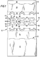
- Blank 10 can be used for forming a canon for packaging six articles such as tubs of yoghurt and according comprises three article retaining means along each side.
- Top panel 12 and side panel 14 comprise article top retaining slits 32 whilst bevel strip 16 comprises heel retaining apertures 34.
- blank 10 can be adapted to accommodate any number of articles in any number of rows.
- Bevel strip 16 is in turn hingably connected to a base panel 18 comprising a first side portion 20, a central portion 22 and a second side portion 24. Central portion 22 is hingably connected along fold lines 56 and 58 to side portions 20 and 24 respectively. However, the fold lines are interrupted by keel structures 36 which, when erected in the completed carton, act to separate two adjacent articles.
- Base panel 18 is in turn hingably connected to bevel strip 26 comprising heel anchor devices 34.
- Bevel strip 26 is in turn hingably connected to a second side panel 28 which is hingably connected to a top panel joining strip 30 which can be attached to top panel 12 for example by using adhesive or cooperating locking means such as a locking tab and cooperating apertures
- each keel structure 36 comprises an article abutting panel 40 which is hingably connected to the base panel 18 along fold line 58 and operably struck out of the plane of the carton panel to a substantially upright position.
- the first upright panel 40 is cut from base side portion 24 along cut line 62 and is hingably connected to a foldable panel 44 along fold line 42.
- Foldable panels 44 and 50, and upper panel 48 are struck from base panel 18 by cut line 64 and thereby form a connecting web between the upright panels 40 and 54.
- the upper panel 48 is thereby partially cut away from foldable panels 44 and 50 by curved cut lines 46.
- upper panel, or connecting member 48 is hingably connected to both foldable panels 44 and 50 along relatively short fold lines 66 at the end of cut lines 46.
- the second foldable panel 50 is in turn hingably connected to a second upright member 54 along fold line 52.
- Second upright number 54 is struck from base panel 18 along cut line 62 and hingably connected thereto along fold line 56.
- Figure 2 shows a schematic perspective view of one of the keel structures 36 in a set up or upright position whereby it acts to help retain an article A. Additionally, keel 36 acts to separate article A from an adjacent article (not shown) in an adjacent row
- upper panel 48 and/or upright members 40 and 54 can be raised out of the plane of the base panel 18.
- upright panels 40 and 54 are caused to rotate about fold lines 58 and 56 respectively.
- foldable panels 44 and 50 start to rotate about fold lines 42 and 52 respectively.
- the foldable panels thereby extend the height of upper panel 48 above both the base panel 18 and the uppermost part of upright panels 40 and 54.
- foldable panels 44 and 50 also provides useful recesses defined in pan by cut line 64 which can be used to retain the heel of an associated article
- cut line 64 which can be used to retain the heel of an associated article
- the upright panel is somewhat flexible between these two points and thus provide, to some extent, resilient retention of the associated article which can of course be useful in order not to damage the article.
- This resilience is also provided to some extent by the curved shape of cuts 46 in upper panel 48 and the use of two separated fold lines 66 to join foldable panels 44 and 50 to upper panel 48.
- parts of the foldable panels 44 and 50 extend above the upper panel 48 in the vicinity of the curved region 46 thereof and thus also provide some form of resilience against an abutting article.
- the fold line 46 is shaped to correspond with the shape of the adjacent portion of the article such as the side of article A shown in Figure 2
- keel structure according to the invention could be provided in a panel used to separate different tiers of articles in a multi-tiered package.
- angle subtended between an upright panel such as 40 or 54 and the associated main carton panel such as base panel 18 is not critical but is preferably in the region of 50° to 130° and more preferably 80° to 100° but, of course, can be adapted to suit the shape of a packaged article
Landscapes
- Engineering & Computer Science (AREA)
- Mechanical Engineering (AREA)
- Packages (AREA)
- Cartons (AREA)
- Control And Other Processes For Unpacking Of Materials (AREA)
- Other Liquid Machine Or Engine Such As Wave Power Use (AREA)
- Load-Engaging Elements For Cranes (AREA)
- Treatments For Attaching Organic Compounds To Fibrous Goods (AREA)
- Paper (AREA)
- Polysaccharides And Polysaccharide Derivatives (AREA)
Abstract
Description
Claims (12)
- A keel structure (36) for separating two adjacent and/or retaining articles in a canon, the keel structure (36) being struck from and integral with a base panel (18) of the carton and comprising in opposed relationship first and second upright members (40, 54) having opposite ends at which they are hingably connected to the panel (18), wherein said keel structure further comprises a bridge structure (44, 48, 50) hingably connected with said upright members,
characterised in that each upright member comprises a downwardly facing edge each of which downwardly facing edges is located intermediate the opposite ends of its respective upright member (40 or 54), and is connected to the bridge structure. - A keel structure according to claim 1 wherein the bridge structure comprising a first foldable panel (44) hingably connected at one edge to the first upright member (40) and hingably connected at an opposite edge to a connecting member (48).
- A keel structure according to claim 2 wherein the bridge structure consists of the first foldable panel (44), the connecting member (48) to which the first foldable panel is hingably connected, and a second foldable panel (50) to which the connecting member is hingably connected and which is in turn hingably connected to the second upright member (54).
- A keel structure (36) according to any of claims 1 to 3 which resiliently separates two adjacent articles.
- A keel structure according to claim 4, wherein the connecting member (48) comprises a region (46) which is shaped to be complementary in shape to a proximal portion of an article.
- A keel structure according to claim 5, wherein part of a foldable portion (44 or 50) is positioned to be between said shaped region (46) of the connecting member (48) and an associated article.
- A keel structure according to any of claims 1 to 6, wherein the first upright member (40) comprises a recess for receiving part of an associated article.
- A keel structure according to any of claims 1 to 6, wherein the second upright member (54) comprises a recess for receiving part of an associated article.
- A partition panel for separating tiers or articles in a multi-tier carton comprising a keel structure according to an one of claims 1 to 8.
- A carton comprising a keel structure according to any one of the claims 1 to 8.
- A method for forming a keel structure according to any one of claims 1 to 8, comprising providing a carton blank or partition panel blank from which a panel (18) has been struck to form the members of the future keel structure in the plane of the panel (18), and moving the connecting member (48) out of the plane of the panel (18) thereby to cause the other members of the structure to move out of the plane of the panel, until the keel structure is in an upright position.
- The method according to claim 11 further comprising the step of maintaining the keel in an upright position until an article is loaded adjacent the keel.
Applications Claiming Priority (3)
| Application Number | Priority Date | Filing Date | Title |
|---|---|---|---|
| GBGB9502118.4A GB9502118D0 (en) | 1995-02-03 | 1995-02-03 | Carton blank with erectable keel |
| GB9502118 | 1995-02-03 | ||
| PCT/US1996/001525 WO1996023709A1 (en) | 1995-02-03 | 1996-02-05 | Carton blank with erectable keel |
Publications (2)
| Publication Number | Publication Date |
|---|---|
| EP0807070A1 EP0807070A1 (en) | 1997-11-19 |
| EP0807070B1 true EP0807070B1 (en) | 2000-01-12 |
Family
ID=10769037
Family Applications (1)
| Application Number | Title | Priority Date | Filing Date |
|---|---|---|---|
| EP96907026A Expired - Lifetime EP0807070B1 (en) | 1995-02-03 | 1996-02-05 | Carton blank with erectable keel |
Country Status (10)
| Country | Link |
|---|---|
| EP (1) | EP0807070B1 (en) |
| AT (1) | ATE188665T1 (en) |
| AU (1) | AU5021496A (en) |
| DE (1) | DE69606162T2 (en) |
| DK (1) | DK0807070T3 (en) |
| ES (1) | ES2141484T3 (en) |
| GB (1) | GB9502118D0 (en) |
| GR (1) | GR3032872T3 (en) |
| PT (1) | PT807070E (en) |
| WO (1) | WO1996023709A1 (en) |
Family Cites Families (3)
| Publication number | Priority date | Publication date | Assignee | Title |
|---|---|---|---|---|
| GB9123562D0 (en) * | 1991-11-06 | 1992-01-02 | Mead Corp | Carton with article separating keel structure |
| MA23035A1 (en) * | 1992-11-20 | 1994-07-01 | Mead Corp | KERNEL STRUCTURE IN WRAPPING PACKAGES. |
| FR2698616B1 (en) * | 1992-11-27 | 1995-02-03 | Aries Packaging | Sidewall to form a tubular envelope surrounding juxtaposed pots and pack thus constituted. |
-
1995
- 1995-02-03 GB GBGB9502118.4A patent/GB9502118D0/en active Pending
-
1996
- 1996-02-05 EP EP96907026A patent/EP0807070B1/en not_active Expired - Lifetime
- 1996-02-05 DE DE69606162T patent/DE69606162T2/en not_active Expired - Lifetime
- 1996-02-05 WO PCT/US1996/001525 patent/WO1996023709A1/en not_active Ceased
- 1996-02-05 PT PT96907026T patent/PT807070E/en unknown
- 1996-02-05 AU AU50214/96A patent/AU5021496A/en not_active Abandoned
- 1996-02-05 DK DK96907026T patent/DK0807070T3/en active
- 1996-02-05 AT AT96907026T patent/ATE188665T1/en not_active IP Right Cessation
- 1996-02-05 ES ES96907026T patent/ES2141484T3/en not_active Expired - Lifetime
-
2000
- 2000-03-03 GR GR20000400564T patent/GR3032872T3/en not_active IP Right Cessation
Also Published As
| Publication number | Publication date |
|---|---|
| WO1996023709A1 (en) | 1996-08-08 |
| DE69606162T2 (en) | 2000-06-15 |
| EP0807070A1 (en) | 1997-11-19 |
| GR3032872T3 (en) | 2000-07-31 |
| GB9502118D0 (en) | 1995-03-22 |
| AU5021496A (en) | 1996-08-21 |
| PT807070E (en) | 2000-04-28 |
| ES2141484T3 (en) | 2000-03-16 |
| DE69606162D1 (en) | 2000-02-17 |
| ATE188665T1 (en) | 2000-01-15 |
| DK0807070T3 (en) | 2000-05-08 |
Similar Documents
| Publication | Publication Date | Title |
|---|---|---|
| US6315123B1 (en) | Carton with panel locking means | |
| EP0250237B1 (en) | Multipack for a two tier group of containers | |
| US4703847A (en) | Multipack for flanged primary containers | |
| KR100506870B1 (en) | Article carrier having brace tab | |
| US5031770A (en) | Package with foldable separator tabs for spacing rows of articles | |
| KR20070099546A (en) | Goods carriers and blanks | |
| US6155412A (en) | Wraparound multipack with carrying handle | |
| EP1070671A1 (en) | Beam structure for an article carrier | |
| EP0255337B1 (en) | Multipack carton with automatic panel positioning tabs | |
| US6568585B2 (en) | Carton and carton blank | |
| EP0807070B1 (en) | Carton blank with erectable keel | |
| WO1998031601A1 (en) | Wraparound multipack with carrying handle | |
| WO2005113368A1 (en) | Carton blank | |
| WO1996023709A9 (en) | Carton blank with erectable keel | |
| WO1998050284A1 (en) | Article carrier with integral keel and locking structure | |
| EP1363842B1 (en) | Wraparound carton with a beam structure and blank therefor | |
| EP0956244B1 (en) | Article carrier and blank therefor | |
| US7204369B2 (en) | Wraparound carton with inclined beam structure and blank therefor | |
| WO1998028200A1 (en) | Article carrier and blank therefor | |
| JP2003529496A (en) | Packaged product carriers | |
| AU2002245690A1 (en) | Wraparound carton with a beam structure and blank therefor | |
| EP1218258B1 (en) | Article carrier and blank therefor | |
| AU2003219854A1 (en) | Article carrier and blank therefor | |
| HK1023546B (en) | Wraparound multipack with carrying handle |
Legal Events
| Date | Code | Title | Description |
|---|---|---|---|
| PUAI | Public reference made under article 153(3) epc to a published international application that has entered the european phase |
Free format text: ORIGINAL CODE: 0009012 |
|
| 17P | Request for examination filed |
Effective date: 19970801 |
|
| AK | Designated contracting states |
Kind code of ref document: A1 Designated state(s): AT BE CH DE DK ES FR GB GR IE IT LI NL PT SE |
|
| 17Q | First examination report despatched |
Effective date: 19980310 |
|
| GRAG | Despatch of communication of intention to grant |
Free format text: ORIGINAL CODE: EPIDOS AGRA |
|
| GRAG | Despatch of communication of intention to grant |
Free format text: ORIGINAL CODE: EPIDOS AGRA |
|
| GRAG | Despatch of communication of intention to grant |
Free format text: ORIGINAL CODE: EPIDOS AGRA |
|
| GRAH | Despatch of communication of intention to grant a patent |
Free format text: ORIGINAL CODE: EPIDOS IGRA |
|
| GRAH | Despatch of communication of intention to grant a patent |
Free format text: ORIGINAL CODE: EPIDOS IGRA |
|
| GRAA | (expected) grant |
Free format text: ORIGINAL CODE: 0009210 |
|
| AK | Designated contracting states |
Kind code of ref document: B1 Designated state(s): AT BE CH DE DK ES FR GB GR IE IT LI NL PT SE |
|
| REF | Corresponds to: |
Ref document number: 188665 Country of ref document: AT Date of ref document: 20000115 Kind code of ref document: T |
|
| REG | Reference to a national code |
Ref country code: CH Ref legal event code: NV Representative=s name: KIRKER & CIE SA Ref country code: CH Ref legal event code: EP |
|
| REF | Corresponds to: |
Ref document number: 69606162 Country of ref document: DE Date of ref document: 20000217 |
|
| ET | Fr: translation filed | ||
| REG | Reference to a national code |
Ref country code: IE Ref legal event code: FG4D |
|
| REG | Reference to a national code |
Ref country code: ES Ref legal event code: FG2A Ref document number: 2141484 Country of ref document: ES Kind code of ref document: T3 |
|
| ITF | It: translation for a ep patent filed | ||
| REG | Reference to a national code |
Ref country code: PT Ref legal event code: SC4A Free format text: AVAILABILITY OF NATIONAL TRANSLATION Effective date: 20000126 |
|
| REG | Reference to a national code |
Ref country code: DK Ref legal event code: T3 |
|
| PLBE | No opposition filed within time limit |
Free format text: ORIGINAL CODE: 0009261 |
|
| STAA | Information on the status of an ep patent application or granted ep patent |
Free format text: STATUS: NO OPPOSITION FILED WITHIN TIME LIMIT |
|
| 26N | No opposition filed | ||
| REG | Reference to a national code |
Ref country code: GB Ref legal event code: IF02 |
|
| REG | Reference to a national code |
Ref country code: CH Ref legal event code: PUE Owner name: MEADWESTVACO PACKAGING SYSTEMS, LLC Free format text: THE MEAD CORPORATION#COURTHOUSE PLAZA NE#DAYTON OHIO 45463 (US) -TRANSFER TO- MEADWESTVACO PACKAGING SYSTEMS, LLC#ONE HIGH RIDGE PARK#STAMFORD, CT 06905 (US) |
|
| NLS | Nl: assignments of ep-patents |
Owner name: MEADWESTVACO PACKAGING SYSTEMS LLC Owner name: MW CUSTOM PAPERS, INC (A DELAWARE CORPORATION) |
|
| NLT1 | Nl: modifications of names registered in virtue of documents presented to the patent office pursuant to art. 16 a, paragraph 1 |
Owner name: MW CUSTOM PAPERS, LLC |
|
| PGFP | Annual fee paid to national office [announced via postgrant information from national office to epo] |
Ref country code: AT Payment date: 20070119 Year of fee payment: 12 |
|
| PGFP | Annual fee paid to national office [announced via postgrant information from national office to epo] |
Ref country code: PT Payment date: 20070123 Year of fee payment: 12 |
|
| PGFP | Annual fee paid to national office [announced via postgrant information from national office to epo] |
Ref country code: IE Payment date: 20070226 Year of fee payment: 12 |
|
| PGFP | Annual fee paid to national office [announced via postgrant information from national office to epo] |
Ref country code: SE Payment date: 20070227 Year of fee payment: 12 Ref country code: CH Payment date: 20070227 Year of fee payment: 12 |
|
| PGFP | Annual fee paid to national office [announced via postgrant information from national office to epo] |
Ref country code: DK Payment date: 20070228 Year of fee payment: 12 |
|
| BECA | Be: change of holder's address |
Owner name: *MEADWESTVACO PACKAGING SYSTEMS LLCONE HIGH RIDGE Effective date: 20060703 |
|
| BECH | Be: change of holder |
Owner name: *MEADWESTVACO PACKAGING SYSTEMS LLC Effective date: 20060703 |
|
| BECN | Be: change of holder's name |
Owner name: *MEADWESTVACO PACKAGING SYSTEMS LLC Effective date: 20060703 |
|
| PGFP | Annual fee paid to national office [announced via postgrant information from national office to epo] |
Ref country code: GR Payment date: 20070228 Year of fee payment: 12 |
|
| REG | Reference to a national code |
Ref country code: PT Ref legal event code: MM4A Free format text: LAPSE DUE TO NON-PAYMENT OF FEES Effective date: 20080805 |
|
| REG | Reference to a national code |
Ref country code: DK Ref legal event code: EBP |
|
| REG | Reference to a national code |
Ref country code: CH Ref legal event code: PL |
|
| EUG | Se: european patent has lapsed | ||
| PG25 | Lapsed in a contracting state [announced via postgrant information from national office to epo] |
Ref country code: PT Free format text: LAPSE BECAUSE OF NON-PAYMENT OF DUE FEES Effective date: 20080805 Ref country code: LI Free format text: LAPSE BECAUSE OF NON-PAYMENT OF DUE FEES Effective date: 20080229 Ref country code: CH Free format text: LAPSE BECAUSE OF NON-PAYMENT OF DUE FEES Effective date: 20080229 |
|
| REG | Reference to a national code |
Ref country code: IE Ref legal event code: MM4A |
|
| PG25 | Lapsed in a contracting state [announced via postgrant information from national office to epo] |
Ref country code: AT Free format text: LAPSE BECAUSE OF NON-PAYMENT OF DUE FEES Effective date: 20080205 |
|
| PG25 | Lapsed in a contracting state [announced via postgrant information from national office to epo] |
Ref country code: SE Free format text: LAPSE BECAUSE OF NON-PAYMENT OF DUE FEES Effective date: 20080206 Ref country code: IE Free format text: LAPSE BECAUSE OF NON-PAYMENT OF DUE FEES Effective date: 20080205 Ref country code: DK Free format text: LAPSE BECAUSE OF NON-PAYMENT OF DUE FEES Effective date: 20080229 |
|
| PG25 | Lapsed in a contracting state [announced via postgrant information from national office to epo] |
Ref country code: GR Free format text: LAPSE BECAUSE OF NON-PAYMENT OF DUE FEES Effective date: 20080903 |
|
| PGFP | Annual fee paid to national office [announced via postgrant information from national office to epo] |
Ref country code: FR Payment date: 20120306 Year of fee payment: 17 |
|
| PGFP | Annual fee paid to national office [announced via postgrant information from national office to epo] |
Ref country code: DE Payment date: 20120228 Year of fee payment: 17 |
|
| PGFP | Annual fee paid to national office [announced via postgrant information from national office to epo] |
Ref country code: GB Payment date: 20120224 Year of fee payment: 17 Ref country code: BE Payment date: 20120227 Year of fee payment: 17 Ref country code: IT Payment date: 20120224 Year of fee payment: 17 |
|
| PGFP | Annual fee paid to national office [announced via postgrant information from national office to epo] |
Ref country code: NL Payment date: 20120228 Year of fee payment: 17 |
|
| PGFP | Annual fee paid to national office [announced via postgrant information from national office to epo] |
Ref country code: ES Payment date: 20120227 Year of fee payment: 17 |
|
| BERE | Be: lapsed |
Owner name: *MEADWESTVACO PACKAGING SYSTEMS LLC Effective date: 20130228 |
|
| REG | Reference to a national code |
Ref country code: DE Ref legal event code: R082 Ref document number: 69606162 Country of ref document: DE Representative=s name: CORINNA VOSSIUS IP GROUP PATENT- UND RECHTSANW, DE |
|
| REG | Reference to a national code |
Ref country code: NL Ref legal event code: V1 Effective date: 20130901 |
|
| GBPC | Gb: european patent ceased through non-payment of renewal fee |
Effective date: 20130205 |
|
| PG25 | Lapsed in a contracting state [announced via postgrant information from national office to epo] |
Ref country code: NL Free format text: LAPSE BECAUSE OF NON-PAYMENT OF DUE FEES Effective date: 20130901 |
|
| REG | Reference to a national code |
Ref country code: FR Ref legal event code: ST Effective date: 20131031 |
|
| REG | Reference to a national code |
Ref country code: DE Ref legal event code: R119 Ref document number: 69606162 Country of ref document: DE Effective date: 20130903 |
|
| PG25 | Lapsed in a contracting state [announced via postgrant information from national office to epo] |
Ref country code: IT Free format text: LAPSE BECAUSE OF NON-PAYMENT OF DUE FEES Effective date: 20130205 |
|
| PG25 | Lapsed in a contracting state [announced via postgrant information from national office to epo] |
Ref country code: BE Free format text: LAPSE BECAUSE OF NON-PAYMENT OF DUE FEES Effective date: 20130228 Ref country code: DE Free format text: LAPSE BECAUSE OF NON-PAYMENT OF DUE FEES Effective date: 20130903 Ref country code: GB Free format text: LAPSE BECAUSE OF NON-PAYMENT OF DUE FEES Effective date: 20130205 Ref country code: FR Free format text: LAPSE BECAUSE OF NON-PAYMENT OF DUE FEES Effective date: 20130228 |
|
| REG | Reference to a national code |
Ref country code: ES Ref legal event code: FD2A Effective date: 20140409 |
|
| PG25 | Lapsed in a contracting state [announced via postgrant information from national office to epo] |
Ref country code: ES Free format text: LAPSE BECAUSE OF NON-PAYMENT OF DUE FEES Effective date: 20130206 |