EP0805464A2 - Tap changer - Google Patents
Tap changer Download PDFInfo
- Publication number
- EP0805464A2 EP0805464A2 EP97105732A EP97105732A EP0805464A2 EP 0805464 A2 EP0805464 A2 EP 0805464A2 EP 97105732 A EP97105732 A EP 97105732A EP 97105732 A EP97105732 A EP 97105732A EP 0805464 A2 EP0805464 A2 EP 0805464A2
- Authority
- EP
- European Patent Office
- Prior art keywords
- contact
- mechanical
- switch
- fixed step
- additional
- Prior art date
- Legal status (The legal status is an assumption and is not a legal conclusion. Google has not performed a legal analysis and makes no representation as to the accuracy of the status listed.)
- Granted
Links
Images

Classifications
-
- H—ELECTRICITY
- H01—ELECTRIC ELEMENTS
- H01F—MAGNETS; INDUCTANCES; TRANSFORMERS; SELECTION OF MATERIALS FOR THEIR MAGNETIC PROPERTIES
- H01F29/00—Variable transformers or inductances not covered by group H01F21/00
- H01F29/02—Variable transformers or inductances not covered by group H01F21/00 with tappings on coil or winding; with provision for rearrangement or interconnection of windings
- H01F29/04—Variable transformers or inductances not covered by group H01F21/00 with tappings on coil or winding; with provision for rearrangement or interconnection of windings having provision for tap-changing without interrupting the load current
-
- H—ELECTRICITY
- H01—ELECTRIC ELEMENTS
- H01H—ELECTRIC SWITCHES; RELAYS; SELECTORS; EMERGENCY PROTECTIVE DEVICES
- H01H9/00—Details of switching devices, not covered by groups H01H1/00 - H01H7/00
- H01H9/0005—Tap change devices
- H01H9/0016—Contact arrangements for tap changers
-
- H—ELECTRICITY
- H01—ELECTRIC ELEMENTS
- H01H—ELECTRIC SWITCHES; RELAYS; SELECTORS; EMERGENCY PROTECTIVE DEVICES
- H01H9/00—Details of switching devices, not covered by groups H01H1/00 - H01H7/00
- H01H9/0005—Tap change devices
- H01H9/0038—Tap change devices making use of vacuum switches
Definitions
- the invention relates to a tap changer according to the preamble of the first claim.
- Such a tap changer is already known from DE 42 37 165 C1.
- the switching mechanism consists of an elevator carriage and driven part.
- the elevator carriage is connected to a mechanical contact acting as a pre-selection contact, which can be brought into contact with each of the fixed step contacts and with its free end slides on a contact rail, which in turn is connected to the load discharge via at least one contact resistance and a first vacuum switch .
- the output part is connected to a trailing mechanical switch contact, which can also be connected to each of the fixed step contacts and in turn is connected to the load discharge via a second vacuum switch.
- the object of the invention is to provide a tap changer of the generic type which allows high switching powers, ie the guidance of high load currents, and at the same time offers a high level of functional reliability.
- a particular advantage of the tap changer according to the invention is the fact that the vacuum switch or switches in the switching branch are relieved or relieved by an additional mechanical contact in the stationary state.
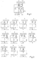
- Figure 3 shows a modified embodiment of the invention.
- the latter is designed so that two individual contact rail parts KS A and KS B are present, between which the additional fixed contact S o is located.
- the two contact rail parts KS A , KS B and the additional contact S o are fixed and are fixed with respect to their relative position to one another on the driven part and are moved with it.
- the function of this embodiment is unchanged, as can be seen from the switching sequence shown in FIG. 4.
Abstract
Description
Die Erfindung betrifft einen Stufenschalter gemäß dem Oberbegriff des ersten Patentanspruches.The invention relates to a tap changer according to the preamble of the first claim.
Ein solcher Stufenschalter ist aus der DE 42 37 165 C1 bereits bekannt.
Bei diesem bekannten Stufenschalter sind sich längs einer Bahn erstreckende feste Stufenkontakte vorgesehen, die durch einen verschiebbaren Schaltmechanismus beschaltbar sind.
Der Schaltmechanismus besteht dabei aus Aufzugsschlitten und Abtriebsteil.
Dabei ist der Aufzugsschlitten mit einem als Vorwählkontakt wirkenden mechanischen Kontakt verbunden, der mit jedem der festen Stufenkontakte in Kontakt bringbar ist und mit seinem freien Ende auf einer Kontaktschiene schleift, wobei diese wiederum über mindestens einem Überschaltwiderstand und einem ersten Vakuumschalter mit der Lastableitung in Verbindung steht.
Das Abtriebsteil ist mit einem nachlaufenden mechanischen Schaltkontakt verbunden, der ebenfalls mit jedem der festen Stufenkontakte in Verbindung bringbar ist und über einen zweiten Vakuumschalter wiederum mit der Lastableitung in Verbindung steht.Such a tap changer is already known from DE 42 37 165 C1.
In this known tap changer, fixed tap contacts extending along a path are provided, which can be connected by a sliding switching mechanism.
The switching mechanism consists of an elevator carriage and driven part.
The elevator carriage is connected to a mechanical contact acting as a pre-selection contact, which can be brought into contact with each of the fixed step contacts and with its free end slides on a contact rail, which in turn is connected to the load discharge via at least one contact resistance and a first vacuum switch .
The output part is connected to a trailing mechanical switch contact, which can also be connected to each of the fixed step contacts and in turn is connected to the load discharge via a second vacuum switch.
Aus der dazugehörigen Zusatzanmeldung DE 43 15 081 A1 ist es auch bereits bekannt geworden, statt des zweiten Vakuumschalters im Abtriebsteil zwei in Reihe geschaltete und zumindest annähernd gleichzeitig betätigbare Vakuumschalter vorzusehen, um die Sicherheit gegen einen möglichen Ausfall eines Vakuumschalters im Schaltzweig zu erhöhen.From the associated additional application DE 43 15 081 A1 it has also become known to provide two vacuum switches connected in series and at least approximately simultaneously operable instead of the second vacuum switch in the stripping section in order to increase the security against a possible failure of a vacuum switch in the switching branch.
Bei diesen bekannten Stufenschaltern fließt jeweils der gesamte Laststrom im stationären Zustand über den Schaltkontakt und den zugeordneten bzw. die zugeordneten Vakuumschalter in diesem Zweig.
Dadurch werden insbesondere bei größeren Lastströmen hohe elektrische Anforderungen an die eingesetzten Vakuumschalter gestellt, was diese unnötig groß und teuer macht.In these known tap changers, the entire load current flows in the stationary state via the switch contact and the associated vacuum switch in this branch.
This places high electrical demands on the vacuum switches used, particularly with larger load currents, which makes them unnecessarily large and expensive.
Aufgabe der Erfindung ist es, einen Stufenschalter der gattungsgemäßen Bauart anzugeben, der hohe Schaltleistungen, d.h die Führung hoher Lastströme, gestattet und zugleich eine hohe Funktionssicherheit bietet.The object of the invention is to provide a tap changer of the generic type which allows high switching powers, ie the guidance of high load currents, and at the same time offers a high level of functional reliability.
Diese Aufgabe wird erfindungsgemäß durch einen Stufenschalter mit den Merkmalen des ersten Patentanspruches gelöst; die Unteranspüche beinhalten besonders vorteilhafte Weiterbildungen der Erfindung.This object is achieved by a tap changer with the features of the first claim; the subclaims contain particularly advantageous developments of the invention.
Besonders vorteilhaft am erfindungsgemäßen Stufenschalter ist die Tatsache, daß durch einen zusätzlichen mechanischen Kontakt im stationären Zustand der bzw. die Vakuumschalter im Schaltzweig entlastet wird bzw. entlastet werden.A particular advantage of the tap changer according to the invention is the fact that the vacuum switch or switches in the switching branch are relieved or relieved by an additional mechanical contact in the stationary state.
Zwar ist die zusätzliche Anordnung von Dauerhauptkontakten parallel zu den Schaltzweigen an sich bereits z.B. aus der DE 44 07 945 C1 bekannt, zu einer verbesserten Dauerstromführung bei einem gattungsgemäßen Stufenschalter kann diese bekannte Lösung jedoch nichts beitragen.The additional arrangement of permanent main contacts parallel to the switching branches is already e.g. Known from DE 44 07 945 C1, however, this known solution cannot contribute to improved continuous current guidance in a step switch of the generic type.
Die Erfindung soll nachfolgend an Hand von zwei Ausführungsbeispielen noch näher erläutert werden.
- Fig. 1
- zeigt eine schematische Darstellung eines ersten erfindungsgemäßen Stufenschalters
- Fig. 2
- zeigt eine entsprechende Schaltsequenz dieses Stufenschalters bei einer Umschaltung vom festen Stufenkontakt n auf den festen Stufenkontakt n+1
- Fig. 3
- zeigt eine schematische Darstellung eines zweiten erfindungsgemäßen Stufenschalters
- Fig. 4
- zeigt wiederum die entsprechende Schaltsequenz dieses Stufenschalters.
Ein zweiter mechanischer Kontakt, der Schaltkontakt SK, ist fest mit einem - hier ebenfalls nicht dargestellten - Abtriebsteil, das nach Auslösung sprungartig dem Aufzugsschlitten nachführbar ist, verbunden und mit diesem bewegbar. Er ist durch eine Reihenschaltung aus einem zweiten Vakuumschalter VS und einem dritten Vakuumschalter VL mit der Lastableitung verbunden. Statt der beschriebenen Reihenschaltung kann auch nur ein einziger Vakuumschalter in diesem Zweig vorhanden sein.
Die Kontaktschiene KS ist ebenfalls fest mit dem Abtriebsteil verbunden.
Auf dem Abtriebsteil ist ein weiterer mechanischer Kontakt So vorgesehen, der demzufolge ebenfalls mit diesem bewegbar ist. Dieser feste Kontakt So ist derart angeordnet, daß er im stationären Zustand, d.h. wenn mechanischer Hilfskontakt HK und mechanischer Schaltkontakt SK am gleichen festen Stufenkontakt n anliegen, von einer zusätzlichen Kontaktstelle HKS des Hilfskontaktes HK beschaltet ist. Dadurch ist im stationären Zustand eine direkte Verbindung vom jeweils geschalteten festen Stufenkontakt, hier n, zum festen Kontakt So und von dort, ggf. über einen weiteren Widerstand Ro zur Lastableitung unter Umgehung der Vakuumschalter VS, VL möglich. Es ist ersichtlich, daß dadurch im stationären Zustand diese Vakuumschalter von der Dauerstromführung entlastet werden.The invention will be explained in more detail below using two exemplary embodiments.
- Fig. 1
- shows a schematic representation of a first tap changer according to the invention
- Fig. 2
- shows a corresponding switching sequence of this tap changer when switching from the fixed tap contact n to the fixed tap contact n + 1
- Fig. 3
- shows a schematic representation of a second tap changer according to the invention
- Fig. 4
- again shows the corresponding switching sequence of this tap changer.
A second mechanical contact, the switching contact SK, is fixedly connected to and movable with a driven part, which is likewise not shown here, which can be tracked to the elevator carriage after it has been triggered. It is connected to the load discharge through a series connection of a second vacuum switch VS and a third vacuum switch VL. Instead of the series connection described, only a single vacuum switch can be present in this branch.
The contact rail KS is also firmly connected to the driven part.
A further mechanical contact S o is provided on the driven part, which consequently can also be moved with it. This fixed contact S o is arranged such that it is in the steady state, ie if mechanical auxiliary contact HK and mechanical switch contact SK are connected to the same fixed step contact n, is connected by an additional contact point HKS of auxiliary contact HK. As a result, in the stationary state, a direct connection from the respectively switched fixed step contact, here n, to the fixed contact S o and from there, possibly via a further resistor R o for load transfer, bypassing the vacuum switches VS, VL, is possible. It can be seen that these vacuum switches are relieved of the continuous current in the stationary state.
Aus der in Figur 2 dargestellten Schaltsequenz ist zu erkennen, daß zu Beginn jeder Umschaltung, wenn der vorlaufende mechanische Hilfskontakt HK den bisherigen festen Stufenkontakt n verläßt, sich die zusätzliche Kontaktstelle HKS vom festen Kontakt So entfernt, so daß der Laststrom auf den in den Zeichnungen links angeordneten Schaltzweig mit der Reihenschaltung der Vakuumschalter VS, VL kommutiert. Zum Abschluß der Lastumschaltung, d.h. wenn der nachlaufende Schaltkontakt den neuen festen Stufenkontakt n+1 erreicht hat, trifft die Kontaktstelle HKS wieder auf den Kontakt So, der, wie erläutert, die Bewegung des Abtriebsteiles und damit des Schaltkontaktes mitvollzogen hat. Die Vakuumschalter VS, VL werden dann wieder von der Dauerstromführung entlastet.From the switching sequence shown in Figure 2 it can be seen that at the beginning of each changeover, when the leading mechanical auxiliary contact HK leaves the previous fixed step contact n, the additional contact point HKS moves away from the fixed contact S o , so that the load current on the in the Drawings on the left arranged switching branch commutated with the series connection of the vacuum switches VS, VL At the end of the load switchover, ie when the trailing switch contact has reached the new fixed step contact n + 1, the contact point HKS again meets the contact S o , which, as explained, has followed the movement of the driven part and thus the switch contact. The vacuum switches VS, VL are then relieved of the continuous current.
Figur 3 zeigt eine modifizierte Ausführungsform der Erfindung. Dabei ist statt einer durchgehenden Kontaktschiene KS diese geteilt ausgeführt, so daß zwei einzelne Kontaktschienenteile KSA und KSB vorhanden sind, zwischen denen der zusätzliche feste Kontakt So sich befindet. Auch hierbei sind die beiden Kontaktschienenteile KSA, KSB und der zusätzliche Kontakt So fest und hinsichtlich ihrer relativen Lage zueinander fixiert auf dem Abtriebsteil angeordnet und werden mit diesem bewegt. Die Funktion dieser Ausführungsform ist, wie sich aus der in Figur 4 dargestellten Schaltsequenz ergibt, unverändert.Figure 3 shows a modified embodiment of the invention. In this case, instead of a continuous contact rail KS, the latter is designed so that two individual contact rail parts KS A and KS B are present, between which the additional fixed contact S o is located. Here, too, the two contact rail parts KS A , KS B and the additional contact S o are fixed and are fixed with respect to their relative position to one another on the driven part and are moved with it. The function of this embodiment is unchanged, as can be seen from the switching sequence shown in FIG. 4.
Letztendlich ist es eine Frage des vorhandenen Platzes und der Dimensionierung der beschriebenen Bauteile, ob man den zusätzlichen mechanischen Kontakt So in einer zusätzlichen Ebene vorsieht oder ihn in die Ebene der Kontaktschiene, die dann geteilt wird, integriert. Wesentlich ist lediglich, daß der feste Kontakt So räumlich so auf dem Abtriebsteil angeordnet ist, daß er im stationären Zustand - und nur in diesem - von der zusätzlichen Kontaktstelle HKS des mechanischen Hilfskontaktes HK kontaktierbar ist.Ultimately, it is a question of the available space and the dimensioning of the components described, whether the additional mechanical contact S o is provided on an additional level or integrated into the level of the contact rail, which is then divided. It is only essential that the fixed contact S o is spatially arranged on the driven part in such a way that it can be contacted in the stationary state - and only in this - by the additional contact point HKS of the mechanical auxiliary contact HK.
Claims (1)
wobei der Schaltmechanismus aus einem direkt antreibbaren Aufzugsschlitten und einem Abtriebsteil, das nach Auslösung sprungartig dem Aufzugsschlitten nachläuft, besteht,
wobei der Aufzugsschlitten mit einem vorwählenden mechanischen Hilfskontakt verbunden ist,
der mit jedem der festen Stufenkontakte in Kontakt bringbar ist und über mindestens einem Überschaltwiderstand und einem ersten Vakuumschalter mit der Lastableitung elektrisch in Verbindung steht,
wobei das Abtriebsteil mit einem mechanischen Schaltkontakt verbunden ist, der ebenfalls mit jedem der festen Stufenkontakte in Kontakt bringbar ist und der über einen zweiten Vakuumschalter oder eine Reihenschaltung aus einem zweiten und einem dritten Vakuumschalter mit der Lastableitung elektrisch in Verbindung steht
und wobei im stationären Zustand mechanischer Hilfskontakt und mechanischer Schaltkontakt am gleichen festen Stufenkontakt anliegen,
dadurch gekennzeichnet,
daß der vorwählende mechanische Hilfskontakt (HK) eine weitere Kontaktstelle (HKS) aufweist,
daß auf dem Abtriebsteil ein zusätzlicher mechanischer fester Kontakt (So) vorgesehen ist, der direkt oder über mindestens einen weiteren Überschaltwiderstand (Ro) mit der Lastableitung (L) elektrisch in Verbindung steht
und daß im stationären Zustand die weitere Kontaktstelle (HKS) des vorwählenden mechanischen Hilfskontaktes (HK) am zusätzlichen Kontakt (So) anliegt, derart, daß dann der jeweils beschaltete feste Stufenkontakt (n, n+1) ohne Zwischenschaltung von Vakuumschaltern (VS, VL) direkt mit der Lastableitung (L) elektrisch in Verbindung steht.Step switches with linear contact actuation, with fixed step contacts extending along a path into the interior of the switch and being switchable by a sliding switching mechanism,
wherein the switching mechanism consists of a directly drivable elevator carriage and an output part which, after being triggered, jumps after the elevator carriage,
the elevator carriage being connected to a preselecting mechanical auxiliary contact,
which can be brought into contact with each of the fixed step contacts and is electrically connected to the load discharge via at least one contact resistor and a first vacuum switch,
wherein the output part is connected to a mechanical switch contact, which can also be brought into contact with each of the fixed step contacts and which is electrically connected to the load lead via a second vacuum switch or a series connection of a second and a third vacuum switch
and in the steady state mechanical auxiliary contact and mechanical switching contact are present on the same fixed step contact,
characterized,
that the preselecting mechanical auxiliary contact (HK) has another contact point (HKS),
that an additional mechanical fixed contact (S o ) is provided on the output part, which is electrically connected directly or via at least one additional switching resistor (R o ) to the load lead (L)
and that in the stationary state the further contact point (HKS) of the preselecting mechanical auxiliary contact (HK) is connected to the additional contact (S o ), such that the fixed step contact (n, n + 1) connected in each case then without the interposition of vacuum switches (VS, VL) is directly connected to the load conductor (L).
Applications Claiming Priority (2)
| Application Number | Priority Date | Filing Date | Title |
|---|---|---|---|
| DE19617506 | 1996-05-02 | ||
| DE19617506A DE19617506C1 (en) | 1996-05-02 | 1996-05-02 | Tap changer |
Publications (3)
| Publication Number | Publication Date |
|---|---|
| EP0805464A2 true EP0805464A2 (en) | 1997-11-05 |
| EP0805464A3 EP0805464A3 (en) | 1999-01-07 |
| EP0805464B1 EP0805464B1 (en) | 2002-02-13 |
Family
ID=7793042
Family Applications (1)
| Application Number | Title | Priority Date | Filing Date |
|---|---|---|---|
| EP97105732A Expired - Lifetime EP0805464B1 (en) | 1996-05-02 | 1997-04-08 | Tap changer |
Country Status (3)
| Country | Link |
|---|---|
| EP (1) | EP0805464B1 (en) |
| AT (1) | ATE213357T1 (en) |
| DE (2) | DE19617506C1 (en) |
Families Citing this family (1)
| Publication number | Priority date | Publication date | Assignee | Title |
|---|---|---|---|---|
| DE102004052316B3 (en) * | 2004-10-28 | 2005-12-01 | Maschinenfabrik Reinhausen Gmbh | Switching method for measuring switch times on an on-load step switch attaches a test circuit to electric switch elements inside a step switch with a separate source of voltage |
Citations (4)
| Publication number | Priority date | Publication date | Assignee | Title |
|---|---|---|---|---|
| FR2330197A1 (en) * | 1975-10-29 | 1977-05-27 | Asea Ab | STEP SWITCH |
| DE4237165C1 (en) * | 1992-11-04 | 1994-03-17 | Reinhausen Maschf Scheubeck | Single-pole tap changer with linear contact actuation for a tap transformer |
| DE4315081A1 (en) * | 1992-11-04 | 1994-11-10 | Reinhausen Maschf Scheubeck | Single-pole stepping switch having linear contact operation |
| DE4407945C1 (en) * | 1994-03-09 | 1995-10-12 | Reinhausen Maschf Scheubeck | Switching device for load change-over or load selection switch |
-
1996
- 1996-05-02 DE DE19617506A patent/DE19617506C1/en not_active Expired - Fee Related
-
1997
- 1997-04-08 AT AT97105732T patent/ATE213357T1/en not_active IP Right Cessation
- 1997-04-08 EP EP97105732A patent/EP0805464B1/en not_active Expired - Lifetime
- 1997-04-08 DE DE59706355T patent/DE59706355D1/en not_active Expired - Fee Related
Patent Citations (4)
| Publication number | Priority date | Publication date | Assignee | Title |
|---|---|---|---|---|
| FR2330197A1 (en) * | 1975-10-29 | 1977-05-27 | Asea Ab | STEP SWITCH |
| DE4237165C1 (en) * | 1992-11-04 | 1994-03-17 | Reinhausen Maschf Scheubeck | Single-pole tap changer with linear contact actuation for a tap transformer |
| DE4315081A1 (en) * | 1992-11-04 | 1994-11-10 | Reinhausen Maschf Scheubeck | Single-pole stepping switch having linear contact operation |
| DE4407945C1 (en) * | 1994-03-09 | 1995-10-12 | Reinhausen Maschf Scheubeck | Switching device for load change-over or load selection switch |
Also Published As
| Publication number | Publication date |
|---|---|
| EP0805464A3 (en) | 1999-01-07 |
| DE19617506C1 (en) | 1997-11-27 |
| DE59706355D1 (en) | 2002-03-21 |
| EP0805464B1 (en) | 2002-02-13 |
| ATE213357T1 (en) | 2002-02-15 |
Similar Documents
| Publication | Publication Date | Title |
|---|---|---|
| EP3427284B1 (en) | On-load tap changer device | |
| EP0650637B1 (en) | Step switch | |
| EP2539909B1 (en) | Tap changer | |
| EP0907193B1 (en) | Tap changer | |
| WO2010115486A1 (en) | On-load tap changer comprising semiconductor switching elements | |
| DE4407945C1 (en) | Switching device for load change-over or load selection switch | |
| DE3619587C2 (en) | ||
| DE4237165C1 (en) | Single-pole tap changer with linear contact actuation for a tap transformer | |
| DE102006033422B3 (en) | Vacuum switching tube for load diverter of on-load tap changer, has upper/lower resistance contact plungers axially movable and electrical conductively guided to other plungers, where contact plungers are operated by respective plungers | |
| EP0252400B1 (en) | Tap selector for tapped transformers equipped with a preliminary selector | |
| EP0805464B1 (en) | Tap changer | |
| DE19518272C1 (en) | Tap-switch for transformers | |
| DE3000748C2 (en) | Step switch for a three-phase transformer with vacuum switches connected in a star configuration | |
| WO2015176918A1 (en) | Switching arrangement for a tap-changing transformer and method for operating a switching arrangement of this kind | |
| EP0895263A2 (en) | Arrangement for switching on electric loads one at a time | |
| DE102010024612B4 (en) | step switch | |
| DE2355514B2 (en) | Diverter switch for transformers | |
| EP4226403A1 (en) | On-load tap changer and method for actuating an on-load tap changer | |
| EP0158995A2 (en) | Tension supply | |
| DE4315081A1 (en) | Single-pole stepping switch having linear contact operation | |
| DE1005596B (en) | Suspension switch for one-hand operation of hoist and chassis motors | |
| WO2022053239A1 (en) | On-load tap changer and method for actuating an on-load tap changer | |
| DE2163239B2 (en) | Electrical switch device, in particular for controlling a central heating system | |
| DE3017395A1 (en) | Motor operated headlamp position adjusting drive - has hand-operated position selector switch and amplifier-controlled motor feed | |
| WO1993009555A1 (en) | Drive for a power switch pole |
Legal Events
| Date | Code | Title | Description |
|---|---|---|---|
| PUAI | Public reference made under article 153(3) epc to a published international application that has entered the european phase |
Free format text: ORIGINAL CODE: 0009012 |
|
| AK | Designated contracting states |
Kind code of ref document: A2 Designated state(s): AT DE GB SE |
|
| PUAL | Search report despatched |
Free format text: ORIGINAL CODE: 0009013 |
|
| AK | Designated contracting states |
Kind code of ref document: A3 Designated state(s): AT DE GB SE |
|
| 17P | Request for examination filed |
Effective date: 19990122 |
|
| GRAG | Despatch of communication of intention to grant |
Free format text: ORIGINAL CODE: EPIDOS AGRA |
|
| GRAG | Despatch of communication of intention to grant |
Free format text: ORIGINAL CODE: EPIDOS AGRA |
|
| GRAH | Despatch of communication of intention to grant a patent |
Free format text: ORIGINAL CODE: EPIDOS IGRA |
|
| 17Q | First examination report despatched |
Effective date: 20010719 |
|
| GRAH | Despatch of communication of intention to grant a patent |
Free format text: ORIGINAL CODE: EPIDOS IGRA |
|
| GRAA | (expected) grant |
Free format text: ORIGINAL CODE: 0009210 |
|
| REG | Reference to a national code |
Ref country code: GB Ref legal event code: IF02 |
|
| AK | Designated contracting states |
Kind code of ref document: B1 Designated state(s): AT DE GB SE |
|
| REF | Corresponds to: |
Ref document number: 213357 Country of ref document: AT Date of ref document: 20020215 Kind code of ref document: T |
|
| GBT | Gb: translation of ep patent filed (gb section 77(6)(a)/1977) |
Effective date: 20020215 |
|
| REF | Corresponds to: |
Ref document number: 59706355 Country of ref document: DE Date of ref document: 20020321 |
|
| PLBE | No opposition filed within time limit |
Free format text: ORIGINAL CODE: 0009261 |
|
| STAA | Information on the status of an ep patent application or granted ep patent |
Free format text: STATUS: NO OPPOSITION FILED WITHIN TIME LIMIT |
|
| 26N | No opposition filed |
Effective date: 20021114 |
|
| PGFP | Annual fee paid to national office [announced via postgrant information from national office to epo] |
Ref country code: AT Payment date: 20040401 Year of fee payment: 8 |
|
| PGFP | Annual fee paid to national office [announced via postgrant information from national office to epo] |
Ref country code: GB Payment date: 20040402 Year of fee payment: 8 |
|
| PGFP | Annual fee paid to national office [announced via postgrant information from national office to epo] |
Ref country code: DE Payment date: 20050302 Year of fee payment: 9 |
|
| PG25 | Lapsed in a contracting state [announced via postgrant information from national office to epo] |
Ref country code: GB Free format text: LAPSE BECAUSE OF NON-PAYMENT OF DUE FEES Effective date: 20050408 Ref country code: AT Free format text: LAPSE BECAUSE OF NON-PAYMENT OF DUE FEES Effective date: 20050408 |
|
| PGFP | Annual fee paid to national office [announced via postgrant information from national office to epo] |
Ref country code: SE Payment date: 20050415 Year of fee payment: 9 |
|
| GBPC | Gb: european patent ceased through non-payment of renewal fee |
Effective date: 20050408 |
|
| PG25 | Lapsed in a contracting state [announced via postgrant information from national office to epo] |
Ref country code: SE Free format text: LAPSE BECAUSE OF NON-PAYMENT OF DUE FEES Effective date: 20060409 |
|
| PG25 | Lapsed in a contracting state [announced via postgrant information from national office to epo] |
Ref country code: DE Free format text: LAPSE BECAUSE OF NON-PAYMENT OF DUE FEES Effective date: 20061101 |
|
| EUG | Se: european patent has lapsed |