EP0804690B1 - A screw - Google Patents
A screw Download PDFInfo
- Publication number
- EP0804690B1 EP0804690B1 EP96900224A EP96900224A EP0804690B1 EP 0804690 B1 EP0804690 B1 EP 0804690B1 EP 96900224 A EP96900224 A EP 96900224A EP 96900224 A EP96900224 A EP 96900224A EP 0804690 B1 EP0804690 B1 EP 0804690B1
- Authority
- EP
- European Patent Office
- Prior art keywords
- screw
- head
- cylindric
- diameter
- washer
- Prior art date
- Legal status (The legal status is an assumption and is not a legal conclusion. Google has not performed a legal analysis and makes no representation as to the accuracy of the status listed.)
- Expired - Lifetime
Links
- 230000004323 axial length Effects 0.000 claims description 12
- 239000002023 wood Substances 0.000 claims description 7
- 208000027418 Wounds and injury Diseases 0.000 description 6
- 230000006378 damage Effects 0.000 description 6
- 208000014674 injury Diseases 0.000 description 6
- 238000009413 insulation Methods 0.000 description 5
- 238000005259 measurement Methods 0.000 description 4
- 241001465754 Metazoa Species 0.000 description 3
- 238000003754 machining Methods 0.000 description 3
- 239000000047 product Substances 0.000 description 2
- 239000004677 Nylon Substances 0.000 description 1
- 229910000831 Steel Inorganic materials 0.000 description 1
- 230000007547 defect Effects 0.000 description 1
- 238000005553 drilling Methods 0.000 description 1
- 239000012467 final product Substances 0.000 description 1
- 238000004519 manufacturing process Methods 0.000 description 1
- 239000000463 material Substances 0.000 description 1
- 238000012986 modification Methods 0.000 description 1
- 230000004048 modification Effects 0.000 description 1
- 229920001778 nylon Polymers 0.000 description 1
- 230000035515 penetration Effects 0.000 description 1
- 238000000053 physical method Methods 0.000 description 1
- 230000000630 rising effect Effects 0.000 description 1
- 239000010959 steel Substances 0.000 description 1
- 238000005728 strengthening Methods 0.000 description 1
Images


Classifications
-
- F—MECHANICAL ENGINEERING; LIGHTING; HEATING; WEAPONS; BLASTING
- F16—ENGINEERING ELEMENTS AND UNITS; GENERAL MEASURES FOR PRODUCING AND MAINTAINING EFFECTIVE FUNCTIONING OF MACHINES OR INSTALLATIONS; THERMAL INSULATION IN GENERAL
- F16B—DEVICES FOR FASTENING OR SECURING CONSTRUCTIONAL ELEMENTS OR MACHINE PARTS TOGETHER, e.g. NAILS, BOLTS, CIRCLIPS, CLAMPS, CLIPS OR WEDGES; JOINTS OR JOINTING
- F16B35/00—Screw-bolts; Stay-bolts; Screw-threaded studs; Screws; Set screws
- F16B35/04—Screw-bolts; Stay-bolts; Screw-threaded studs; Screws; Set screws with specially-shaped head or shaft in order to fix the bolt on or in an object
- F16B35/041—Specially-shaped shafts
- F16B35/048—Specially-shaped necks
-
- F—MECHANICAL ENGINEERING; LIGHTING; HEATING; WEAPONS; BLASTING
- F16—ENGINEERING ELEMENTS AND UNITS; GENERAL MEASURES FOR PRODUCING AND MAINTAINING EFFECTIVE FUNCTIONING OF MACHINES OR INSTALLATIONS; THERMAL INSULATION IN GENERAL
- F16B—DEVICES FOR FASTENING OR SECURING CONSTRUCTIONAL ELEMENTS OR MACHINE PARTS TOGETHER, e.g. NAILS, BOLTS, CIRCLIPS, CLAMPS, CLIPS OR WEDGES; JOINTS OR JOINTING
- F16B35/00—Screw-bolts; Stay-bolts; Screw-threaded studs; Screws; Set screws
- F16B35/04—Screw-bolts; Stay-bolts; Screw-threaded studs; Screws; Set screws with specially-shaped head or shaft in order to fix the bolt on or in an object
- F16B35/06—Specially-shaped heads
-
- F—MECHANICAL ENGINEERING; LIGHTING; HEATING; WEAPONS; BLASTING
- F16—ENGINEERING ELEMENTS AND UNITS; GENERAL MEASURES FOR PRODUCING AND MAINTAINING EFFECTIVE FUNCTIONING OF MACHINES OR INSTALLATIONS; THERMAL INSULATION IN GENERAL
- F16B—DEVICES FOR FASTENING OR SECURING CONSTRUCTIONAL ELEMENTS OR MACHINE PARTS TOGETHER, e.g. NAILS, BOLTS, CIRCLIPS, CLAMPS, CLIPS OR WEDGES; JOINTS OR JOINTING
- F16B5/00—Joining sheets or plates, e.g. panels, to one another or to strips or bars parallel to them
- F16B5/02—Joining sheets or plates, e.g. panels, to one another or to strips or bars parallel to them by means of fastening members using screw-thread
- F16B5/0275—Joining sheets or plates, e.g. panels, to one another or to strips or bars parallel to them by means of fastening members using screw-thread the screw-threaded element having at least two axially separated threaded portions
-
- F—MECHANICAL ENGINEERING; LIGHTING; HEATING; WEAPONS; BLASTING
- F16—ENGINEERING ELEMENTS AND UNITS; GENERAL MEASURES FOR PRODUCING AND MAINTAINING EFFECTIVE FUNCTIONING OF MACHINES OR INSTALLATIONS; THERMAL INSULATION IN GENERAL
- F16B—DEVICES FOR FASTENING OR SECURING CONSTRUCTIONAL ELEMENTS OR MACHINE PARTS TOGETHER, e.g. NAILS, BOLTS, CIRCLIPS, CLAMPS, CLIPS OR WEDGES; JOINTS OR JOINTING
- F16B23/00—Specially shaped nuts or heads of bolts or screws for rotations by a tool
- F16B23/0007—Specially shaped nuts or heads of bolts or screws for rotations by a tool characterised by the shape of the recess or the protrusion engaging the tool
- F16B23/003—Specially shaped nuts or heads of bolts or screws for rotations by a tool characterised by the shape of the recess or the protrusion engaging the tool star-shaped or multi-lobular, e.g. Torx-type, twelve-point star
-
- F—MECHANICAL ENGINEERING; LIGHTING; HEATING; WEAPONS; BLASTING
- F16—ENGINEERING ELEMENTS AND UNITS; GENERAL MEASURES FOR PRODUCING AND MAINTAINING EFFECTIVE FUNCTIONING OF MACHINES OR INSTALLATIONS; THERMAL INSULATION IN GENERAL
- F16B—DEVICES FOR FASTENING OR SECURING CONSTRUCTIONAL ELEMENTS OR MACHINE PARTS TOGETHER, e.g. NAILS, BOLTS, CIRCLIPS, CLAMPS, CLIPS OR WEDGES; JOINTS OR JOINTING
- F16B43/00—Washers or equivalent devices; Other devices for supporting bolt-heads or nuts
-
- Y—GENERAL TAGGING OF NEW TECHNOLOGICAL DEVELOPMENTS; GENERAL TAGGING OF CROSS-SECTIONAL TECHNOLOGIES SPANNING OVER SEVERAL SECTIONS OF THE IPC; TECHNICAL SUBJECTS COVERED BY FORMER USPC CROSS-REFERENCE ART COLLECTIONS [XRACs] AND DIGESTS
- Y10—TECHNICAL SUBJECTS COVERED BY FORMER USPC
- Y10S—TECHNICAL SUBJECTS COVERED BY FORMER USPC CROSS-REFERENCE ART COLLECTIONS [XRACs] AND DIGESTS
- Y10S411/00—Expanded, threaded, driven, headed, tool-deformed, or locked-threaded fastener
- Y10S411/919—Screw having driving contacts
Definitions
- the present invention relates to an integral screw, preferably a woodscrew, including a threaded stem portion having a free end and a root end integral with and corresponding in diameter to a minor base end of a co-axial frustoconical portion projecting axially from said root end, a convexly shaped head section near a major base end of the frustoconical portion, said head section being provided with centrally disposed screwdriver tool engagement recess compatible with a predetermined tool for driving said screw.
- Wood screws belong to the most widely used fasteners in many different applications. For instance, it is often required that a wood screw be capable of fixedly holding a hardware such as a hinge wing or railway clamp. Another requirement often raised is that the specific axial pressure active under the screw head of a tightened screw be as low as possible while securing a firm hold. Another requisite is that the screw be capable of being applied without the need for countersinking the head as this may require an extra machining of at least one of the parts being joined. By the same token, it is often required that the screw positioned in place be as unobtrusive as possible on the surface to avoid the danger of injury, for instance, to animals in zoo structures, to children and to the general user.
- the torque tool engaging projection is known to be replaced with various cutouts compatible with tools such as screwdrivers and a variety of these exists, from plain straight grooves as in Canadian Patent 27,387 (Rogers), to more complex sockets such as shown e.g. in US Patent 5,249,882 (Nagoshi et al.), Canadian Patent 400,454 (Purtell), Canadian Patent 1,248,374 (Rockenfeller et al.) or Published Canadian Patent Application 2,094,478 (Goss).
- GB-A-2072781 shows a similar screw with a strengthening portion under the head.
- Prior art screws are usually unsuitable for use with power tools, where the screw must often withstand a relatively high torque while a low specific pressure under the head is required when the fastener is firmly in place.
- the screws having convexly shaped heads project above the surface of the workpiece often in obtrusive and potentially dangerous way which may cause injury.
- the invention provides a screw of the aforesaid type, in which the head section includes a shallowly convex head portion which is integral with a washer portion.
- the washer portion includes a flat underside and a flat annular upper face concentric with the head portion and having a minor diameter equal to that of the head portion and a major diameter greater than that of the head portion.
- An integral cylindric portion is located between the major base end and the flat underside to not only strengthen the structure of the screw making it more suitable for power tool drive, but also to provide a cylindric guide surface compatible with a pre-machined opening, e.g. in a hinge wing.
- the axial length of the head portion is greater than the thickness of the washer portion, preferably by a ratio whereby the thickness of the washer portion is about 0.75 to about 0.9 of the axial length of the head portion.
- This ratio combined with concave screwdriver engagement cavity in the head, provide for a smooth and safe surface, where the head and the washer do not present a potential source of injury or the like.
- the diameter of the cylindric portion be larger than axial length thereof, to provide an improved strength and a length of the cylindric portion sufficient, on the one hand, to safely engage a pre-machined bore of, say, a hinge wing, while avoiding, on the other hand, the need for machining a recess in the base to accommodate the increased diameter of the cylindric portion.
- the screw shown in the drawings is an integral product made from suitable steel, it being understood that certain applications may warrant or require different material, for instance nylon.
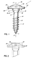
- the screw shown in the drawings comprises a stem portion 10.
- the stem portion has a free end portion 11 which, in the embodiment shown, is pointed.
- the opposite end of the stem 10 is designated as a root end 12.
- a major part of the stem portion 10 is cylindric, the only deviation being at the pointed free end 11 where the shape is conical.
- a helical thread 13 projects from the surface of the stem portion 10. It extends from the pointed free end 11 and terminates at a root end portion 14 of the thread 13, which is spaced from the root end 12 of the stem 10.
- the root end 12 of the stem 10 is integral with a minor base end 15 of a frustoconical portion 16.
- the diameter of the root end 12 is the same as that of the minor base portion 15.
- the frustoconical portion 16 projects axially from the root end 12 and is coaxial with the root end about a common axis 17 of the screw.
- the opposite end of the frustoconical portion 16 is a major base end 18.
- the major base end 18 coincides with, and thus has the same diameter as a first end 19 of a root cylindric portion 20.
- the portions 18, 19 are integral and co-axial with the axis 17 and with each other.
- Figs. 3 and 4 show that the diameter B1 (Fig. 4) is a multiple of that B3 (Fig. 3) of the second cylindric portion 20.
- the washer section 23 defines a flat, annular upper face section 24. It is parallel with and is turned away from the underside 22.
- a centrally disposed, coaxial, shallowly convex head portion 25 projects upwardly from the upper face section 24.
- the head portion 25 is provided with centrally disposed drive tool engagement recess 26.
- the particular contour in plan of the recess is shown in Fig. 5. It is to be appreciated, however, that the specific type of the recess 26 is not a part of this invention and is optional. It has to be compatible with a predetermined tool for driving the screw into a base and preferably is suitable for use with a power tool when the screw is to be used in manufacturing furniture, wooden structures or other products where power screw driving tools are required.
- the axial length A3 of the root cylindric portion 20 be smaller than its diameter B3 (Fig. 3) as this arrangement facilitates the application of the screw without the need of pre-drilling a bore in the workpiece and it also improves the torque strength of the screw.
- Another preferred feature is that while the specific diameter B2 of the head 25 is of course, smaller than the diameter B1 of the washer section 23 it is larger than the diameter B3 of the root cylindric portion 20.
- the latter diameter B3 may be dictated by the size of bores in hardware with which the screw is to be used, for instance a hinge wing.
- the shallowly convex shape of the head portion combines with the particular physical structure of the washer section 23 to provide a relatively smooth, graduated rising of the head portion of the screw above the surface of the workpiece without sudden high corners which might cause injury, for instance to animals in zoo structures.
- the term "shallowly" convex used to describe the head portion 25 designates the general condition where the ratio of the axial length A1 of the head portion 25 to its diameter B2 is in the range of about 0.15 to about 0.25, thus, the axial height of the head portion 25 above the washer section 23 is less than about 1 ⁇ 4 of the diameter of the head portion 25 at the upper surface of the washer section 25.
- the ratio of the thickness A2 of the washer section 23 to the axial length A1 of the head portion 25 be in the range of about 0.75 to about 0.9, in other words, the thickness A2 of the washer 23 is smaller than the height A1 of the convex head portion 25.
- Table 1 presents three examples of different embodiments of the screw of the present invention, having typical physical measurements of individual portions of the screw.
- the three embodiments shown are 6, 7 and 8 mm which roughly corresponds to 1/4"; 5/16" and 3/8" wood screws each having a total length of about 80 mm, respectively.
- the respective size particulars of the inventive screw, are described using reference characters of Figs. 3 and 4.
- FIG. 5 One such embodiment, which generally corresponds to the embodiments shown in the preceding table, is diagrammatically shown in Figs. 5 and 6.
- the corresponding parts of the representation of Figs. 5 and 6 is provided with the same reference numbers as in Figs. 1- 4 increased by 100.
- Figs. 1 - 4. there is a stem portion 110 having a pointed free end portion 111 and a root end 112.
- the difference over the first group of embodiments is in that the cylindric stem 110 is longer and the helical thread is split into two sections: 113a at the tip 111, and 113b at the root end 112.
- the intermediate section 113c is cylindric.
- the measurements of the screw of Fig. 5 and 6 are optional, it should be noted that the measurements C1 - D4 could generally correspond to those of Al - B4 of Figs. 1 - 4.
- the stem 110 would typically be longer, from about 135 mm to about 340 mm. Within such range, the length of the threaded portion 113a would be about 50-75 mm, the intermediate, unthreaded portion 113c would be about 50-220 mm long and the length of the upper threaded part 113b would be about 30-45 mm.
- the root end 112 of the stem 110 is integral with a minor base end 115 of a frustoconical portion 116 which projects axially from the root end 112 and is coaxial with the root end about a common axis 117 of the screw.
- the other end 121 of the root cylindric portion 120 merges with the planar underside 122 of a washer section 123.
- the washer section 123 has an upper face section 124.
- a head portion 125 projects from the upper face section 124.
- the head portion 125 is provided with centrally disposed drive tool engagement recess 126.
- the screws can be driven in place either manually or by a power tool.
- the washer portion 23, 123 and its associated head 25, 125 present a minimum protrusion on the surface of a workpiece.
- the intermediate structure components 16, 20, 116, 120 provide the required strength even if the screw is small and a tool engagement cavity is provided. This virtually eliminates the occurrence of time and labour consuming breakages of the screw during an assembly operation and the resulting defects in quality of the final product.
- the cylindric portion 20, 120 provides, if required, the desired engagement surface with a bore of a component to be fixed to a wooden structure, for instance a brace or a hinge.
- the enlarged surface of the washer section 23, 123 maintains a relatively low specific pressure at the face of the workpiece even on a strong tightening of the screw.
- the screw of the present invention manufactured within the above tolerances possesses torque strength which makes it suitable for use with power screw driving tools while utilizing a drive tool engagement cavity or recess 26, 126. It is believed that this is due to an inventive feature whereby the length of the frustoconical portion 16, 116 generally corresponds to that of the root cylindric portion 20, 120.
Landscapes
- Engineering & Computer Science (AREA)
- General Engineering & Computer Science (AREA)
- Mechanical Engineering (AREA)
- Connection Of Plates (AREA)
- Bolts, Nuts, And Washers (AREA)
- Joining Of Building Structures In Genera (AREA)
Description
- Figure 1
- is a diagrammatic, enlarged side view of a wood screw including the combination of features according to the present invention;
- Figure 2
- is a view similar to that of Fig. 1, in which the contour of a prior art screw of comparable size, with a hexagonal head is shown in broken lines for comparison of the contour of an applied screw;
- Figure 3
- is a diagrammatic side view of a screw comprising the combination of the present invention, in which certain measurements are marked to provide examples of a number of variations in size;
- Figure 4
- is a top plan view of Fig. 3;
- Figure 5
- is a view similar to that of Fig. 3 but showing another embodiment of the invention; and
- Figure 6
- is a top plan view of Fig. 5.
| SIZE PARTICULARS OF THREE EMBODIMENTS OF THE INVENTIVE SCREW (in mm) | |||
| Size of the screw | 8 | 7 | 6 |
| | 2.4 | 2 | 1.6 |
| | 1.8-1.5 | 1.6-1.3 | 1.4-1 |
| A3 Axial length of | 2 (max) | 2 (max) | 1.5 (max) |
| A4 Axial length of frustocon. port. 16 | 2 (max) | 2 (max) | (1.5 max) |
| B1 Diameter range of | 18.5-16 | 16.5-14 | 14-12.5 |
| B2 Diameter range of | 10.5-10 | 10-9.7 | 9-8.7 |
| B3 Diameter range of | 9.4-8.9 | 7.8-7.3 | 6.3-5.9 |
| B4 Outer dia. range of | 8-7.5 | 7.2-6.7 | 6.2-5.7 |
| B5 Diameter range of | 5.4-5.1 | 4.82-4.79 | 4.24-4.18 |
Claims (4)
- An integral screw, particularly a wood screw, including a threaded stem portion (10, 110) having a free end (11, 111) and a root end (12, 112) integral with and corresponding in diameter to a minor base end of a co-axial frustoconical portion (16, 116) projecting axially from said root end (12, 112), a convexly shaped head section (23-25, 123-125) near a major base end (18, 118) of the frustoconical portion (16, 116), said head section (23-25, 123-125) being provided with centrally disposed screw drive tool engagement recess (26, 126) compatible with a predetermined tool for driving said screw, a cylindric portion (20, 120) integrally formed with said head section (23-25; 123-125) said cylindric portion being located between the major base end (18, 118) and the head section (23-25; 123-125), said integral frustoconical portion (16, 116) being disposed at an end of the cylindric portion (20, 120) remote from said head section
characterized in that
the head section includes a shallowly convex head portion (25, 125) integrally formed with a washer portion (23, 123), said washer portion comprising a flat underside (22, 122) and a flat annular upper face (24, 124) having a minor diameter equal to that of the head portion (25, 125) and a major diameter greater than that of the head portion (25, 125), the ratio of the axial length (A1, C1) of the head portion (25, 125) to the diameter (B2, D2) thereof is about 0.15 to about 0.25. - The screw as claimed in claim 1, characterized in that the ratio of the thickness (A2, C2) of the washer portion to the axial length (A1, C1) of the head portion (25, 125) is smaller than 1, preferably from about 0.75 to about 0.9.
- The screw as claimed in claim 1 or claim 2, characterized in that the diameter (B3, D3) of the cylindric portion (20, 120) is larger than the axial length (A4, C4) thereof.
- The screw as claimed in any one of claims 1 - 3, characterized in that the axial length of the frustoconical portion (16, 116) is generally equal to that of the cylindric portion (20, 120).
Applications Claiming Priority (3)
| Application Number | Priority Date | Filing Date | Title |
|---|---|---|---|
| CA002140475A CA2140475C (en) | 1995-01-18 | 1995-01-18 | Screw |
| CA2140475 | 1995-01-18 | ||
| PCT/CA1996/000023 WO1996022472A1 (en) | 1995-01-18 | 1996-01-16 | A screw |
Publications (2)
| Publication Number | Publication Date |
|---|---|
| EP0804690A1 EP0804690A1 (en) | 1997-11-05 |
| EP0804690B1 true EP0804690B1 (en) | 1998-11-11 |
Family
ID=4155066
Family Applications (1)
| Application Number | Title | Priority Date | Filing Date |
|---|---|---|---|
| EP96900224A Expired - Lifetime EP0804690B1 (en) | 1995-01-18 | 1996-01-16 | A screw |
Country Status (9)
| Country | Link |
|---|---|
| US (1) | US5919020A (en) |
| EP (1) | EP0804690B1 (en) |
| JP (1) | JP4023628B2 (en) |
| CN (1) | CN1065329C (en) |
| AU (1) | AU4382296A (en) |
| CA (1) | CA2140475C (en) |
| DE (1) | DE69600970T2 (en) |
| TW (1) | TW297470U (en) |
| WO (1) | WO1996022472A1 (en) |
Families Citing this family (43)
| Publication number | Priority date | Publication date | Assignee | Title |
|---|---|---|---|---|
| DE19615191C5 (en) * | 1996-04-17 | 2006-02-09 | Sfs Intec Holding Ag | Screw and method for torque limited mounting of metal and / or plastic profiles or plates on a substructure |
| DE19652318C1 (en) * | 1996-12-16 | 1998-01-22 | Sfs Ind Holding Ag | Fastener for joining panels |
| US6290445B1 (en) * | 2000-04-18 | 2001-09-18 | Avibank Mfg., Inc. | Non-removable structural threaded fastener with threads of lesser outer diameter than the shank and method of forming same |
| US6840704B1 (en) | 2001-01-26 | 2005-01-11 | Brant Monson | Quick release system for motorcycle backrests |
| USD465148S1 (en) | 2001-01-26 | 2002-11-05 | Brant Monson | Bolt |
| USD469006S1 (en) | 2001-01-26 | 2003-01-21 | Brant Monson | Bolt |
| USD466001S1 (en) | 2001-10-19 | 2002-11-26 | Brant Monson | Bolt |
| US6789989B2 (en) * | 2002-03-13 | 2004-09-14 | Uli Walther | Screw having a head with concave underside |
| US20040071524A1 (en) * | 2002-10-11 | 2004-04-15 | Habermehl G. Lyle | Fastener with stepped head for composite decking |
| US7473489B2 (en) * | 2003-09-16 | 2009-01-06 | Okabe Company, Inc. | Battery terminal bolt |
| US7934693B2 (en) * | 2003-11-25 | 2011-05-03 | Bravinski Leonid G | Formwork for erecting reinforced concrete walls, including concrete walls with textured surfaces |
| DE102005022449A1 (en) * | 2005-05-14 | 2006-11-30 | Fischerwerke Artur Fischer Gmbh & Co. Kg | Spacer for the attachment of an object to a substrate having an insulating layer |
| DE102006002559A1 (en) * | 2006-01-10 | 2007-07-12 | Swg Schraubenwerk Gaisbach Gmbh | countersunk |
| US20070166125A1 (en) * | 2006-01-17 | 2007-07-19 | Sukup Manufacturing Company | Pin member for grain bin door |
| DE102006023026A1 (en) * | 2006-05-10 | 2007-11-15 | Reisser Schraubentechnik Gmbh | Fastening unit e.g. screw, for gypsum plasterboard, has shank, and head formed at one end of shank, where head has two step areas with cylindrical external form, which are attached to one another in longitudinal direction of unit |
| US7810890B2 (en) * | 2006-10-13 | 2010-10-12 | Lynk, Inc. | Glide mechanism for roll out drawers and other items |
| ATE481570T1 (en) * | 2007-05-07 | 2010-10-15 | Spax Int Gmbh & Co Kg | FITTING SCREW, ESPECIALLY FOR FURNITURE FITTINGS |
| US7490366B1 (en) * | 2007-07-12 | 2009-02-17 | Milton Richter | Bolt assembly for the attachment of toilet seats and other articles |
| CN102042005A (en) * | 2009-10-12 | 2011-05-04 | 西安威尔罗根能源科技有限公司 | Lithologic density probe fastening screw |
| JP2011256971A (en) * | 2010-06-11 | 2011-12-22 | Pias Hanbai Kk | Tapping screw |
| ES2399121B1 (en) * | 2011-06-06 | 2014-02-11 | BSH Electrodomésticos España S.A. | Elastic fixing device |
| US9446857B2 (en) * | 2012-02-08 | 2016-09-20 | The Boeing Company | Engine cowl and inlet cover |
| DE202012001634U1 (en) * | 2012-02-16 | 2012-03-01 | Joh. Hermann Picard Gmbh & Co. Kg | Wedge screw for attaching wooden stems with steel handle sleeve with large angled contact surface for hammers |
| JP5957257B2 (en) * | 2012-03-27 | 2016-07-27 | 住友林業株式会社 | Wood member joint structure |
| US8794891B1 (en) * | 2013-07-15 | 2014-08-05 | Hirofumi Saito | Round top set screw and application thereof |
| US9518599B2 (en) | 2014-04-10 | 2016-12-13 | Simpson Strong-Tie Company, Inc. | Metal to metal fastener |
| CN104088881A (en) * | 2014-08-04 | 2014-10-08 | 赵静 | Fastening screw for end cover of speed reducer |
| SE538636C2 (en) * | 2014-12-12 | 2016-10-04 | Essve Produkter Ab | Concrete screw |
| DE102015224367A1 (en) * | 2015-12-04 | 2017-06-08 | Ejot Baubefestigungen Gmbh | Fixed or floating point screw |
| AU201614802S (en) | 2016-08-31 | 2016-09-30 | Illinois Tool Works | A screw fastener |
| AU201614800S (en) * | 2016-08-31 | 2016-09-30 | Illinois Tool Works | A screw fastener |
| US10156251B2 (en) * | 2016-11-04 | 2018-12-18 | Ford Global Technologies, Llc | Recessed spring washer flow drill screw |
| USD828149S1 (en) * | 2016-11-30 | 2018-09-11 | Hyundai Motor Company | Bolt |
| WO2019199430A1 (en) * | 2018-04-09 | 2019-10-17 | The Hillman Group, Inc. | Screw-type fastener for concrete and hurricane resistance applications |
| TW202001111A (en) * | 2018-06-22 | 2020-01-01 | 佑泰工業有限公司 | Screw structure |
| USD893987S1 (en) * | 2018-11-14 | 2020-08-25 | Innovative Fasteners Pty Ltd. | One piece fastener |
| CN109434438A (en) * | 2018-12-21 | 2019-03-08 | 珠海经济特区华凯工贸有限公司 | A kind of bearing calibration of manipulator automatic tightening self-tapping screw |
| USD959971S1 (en) * | 2020-08-18 | 2022-08-09 | Kobert & Company, Inc. | Screw |
| USD959970S1 (en) * | 2020-08-18 | 2022-08-09 | Kobert & Company, Inc. | Screw |
| DE102020133619B8 (en) * | 2020-12-15 | 2023-07-06 | Interroll Holding Ag | roller conveyor |
| CN112983939A (en) * | 2021-02-01 | 2021-06-18 | 中国电建集团贵州电力设计研究院有限公司 | Locking device of mountain region photovoltaic fixed adjustable support suitable for manual operation |
| JP7647159B2 (en) * | 2021-02-24 | 2025-03-18 | マックス株式会社 | screw |
| DK181913B1 (en) * | 2023-08-03 | 2025-03-19 | Dissing As | Method for fastening WPC panels to a wooden support and a combination of a drill-bit and a screw |
Family Cites Families (24)
| Publication number | Priority date | Publication date | Assignee | Title |
|---|---|---|---|---|
| US438754A (en) * | 1890-10-21 | Island | ||
| CA400454A (en) * | 1941-11-04 | The Holo-Krome Screw Corporation | Socketed connector | |
| CA27387A (en) * | 1887-08-10 | The American Screw Company | Wood screw | |
| US3236141A (en) * | 1963-11-05 | 1966-02-22 | Robert D Smith | Screw |
| US3304109A (en) * | 1965-04-21 | 1967-02-14 | Hi Shear Corp | Joint including tapered fastener |
| US3313197A (en) * | 1965-09-08 | 1967-04-11 | Illinois Tool Works | Screw |
| US3828422A (en) * | 1970-08-05 | 1974-08-13 | Boeing Co | Method of making fatigue resistant fastener joint |
| BE793109A (en) * | 1971-12-23 | 1973-04-16 | Arnold | FISH THE FIXATION |
| US3882752A (en) * | 1972-02-01 | 1975-05-13 | Elco Industries Inc | Controlled-drive sealing fastener |
| ZA728229B (en) * | 1972-11-21 | 1974-03-27 | Utility Prod Ltd | Recess in fastening element head and method of making it |
| US4254542A (en) * | 1979-04-11 | 1981-03-10 | Craig Gerald V | Construction nut and bolt assembly and method of erecting structural steel |
| GB2072781B (en) * | 1980-03-28 | 1983-12-07 | Gkn Screws Fasteners Ltd | Woodscrew |
| AT368609B (en) * | 1980-10-02 | 1982-10-25 | Sfs Stadler Ag | METAL SCREW |
| JPS57116923A (en) * | 1981-01-12 | 1982-07-21 | Katsuhisa Yamazaki | Drill screw |
| EP0102605B1 (en) * | 1982-09-02 | 1986-08-13 | Rockenfeller KG Befestigungselemente | Wood-screw |
| US4621963A (en) * | 1984-03-26 | 1986-11-11 | Elco Industries, Inc. | Fastener for roof assemblies and the like |
| US4749322A (en) * | 1986-11-24 | 1988-06-07 | Illinois Tool Works Inc. | Aluminum roof panel fastener |
| US4763456A (en) * | 1987-08-03 | 1988-08-16 | Giannuzzi Louis | Roof anchor and stress plate assembly |
| CH681648A5 (en) * | 1990-06-25 | 1993-04-30 | Ver Drahtwerke Ag | |
| GB2251666A (en) * | 1990-11-02 | 1992-07-15 | Council Scient Ind Res | "Screws for roofing sheets" |
| JPH0571521A (en) * | 1991-05-29 | 1993-03-23 | Toopura:Kk | Drilling screw |
| US5141376A (en) * | 1992-02-03 | 1992-08-25 | Emhart Inc. | Self drilling screw |
| US5291811A (en) * | 1992-05-14 | 1994-03-08 | Textron Inc. | Back-side taper wedging drive system |
| GB2273325B (en) * | 1992-12-11 | 1996-05-15 | John Conroy | Wall-mounted suspension fittings using screws |
-
1995
- 1995-01-18 CA CA002140475A patent/CA2140475C/en not_active Expired - Lifetime
- 1995-12-08 US US08/567,884 patent/US5919020A/en not_active Expired - Lifetime
-
1996
- 1996-01-16 EP EP96900224A patent/EP0804690B1/en not_active Expired - Lifetime
- 1996-01-16 JP JP52193396A patent/JP4023628B2/en not_active Expired - Lifetime
- 1996-01-16 WO PCT/CA1996/000023 patent/WO1996022472A1/en not_active Ceased
- 1996-01-16 AU AU43822/96A patent/AU4382296A/en not_active Abandoned
- 1996-01-16 DE DE69600970T patent/DE69600970T2/en not_active Expired - Lifetime
- 1996-01-16 CN CN96192242A patent/CN1065329C/en not_active Expired - Lifetime
- 1996-02-07 TW TW085214107U patent/TW297470U/en unknown
Also Published As
| Publication number | Publication date |
|---|---|
| JPH11502588A (en) | 1999-03-02 |
| DE69600970D1 (en) | 1998-12-17 |
| CA2140475C (en) | 2000-03-07 |
| EP0804690A1 (en) | 1997-11-05 |
| CN1176682A (en) | 1998-03-18 |
| HK1014443A1 (en) | 1999-09-30 |
| DE69600970T2 (en) | 1999-05-12 |
| TW297470U (en) | 1997-02-01 |
| CA2140475A1 (en) | 1996-07-19 |
| WO1996022472A1 (en) | 1996-07-25 |
| US5919020A (en) | 1999-07-06 |
| CN1065329C (en) | 2001-05-02 |
| JP4023628B2 (en) | 2007-12-19 |
| AU4382296A (en) | 1996-08-07 |
Similar Documents
| Publication | Publication Date | Title |
|---|---|---|
| CA2140475C (en) | Screw | |
| US4952110A (en) | Anti-cross thread screw | |
| CA2478635C (en) | A screw having a head with concave underside | |
| US5987837A (en) | Reamer screw and building panels erected with reamer screws | |
| US4944627A (en) | Apparatus and method for joining workpieces | |
| US5599149A (en) | Self-tapping floor screw | |
| AU4707597A (en) | Screw for the mutual securing of at least two components | |
| CN218625002U (en) | Slope-shaped self-locking fastener | |
| CN214742611U (en) | Wood screw for furniture | |
| MXPA02008516A (en) | Washer, fastener provided with a washer, and method of and power tool for fastening with the use of the washer. | |
| EP0125040B1 (en) | A connector for joining two members to one another | |
| CN2132018Y (en) | Torsion spring type thread anti-loosening device | |
| JP2532141Y2 (en) | Frame members | |
| JPH01158813U (en) | ||
| JPH0113847Y2 (en) | ||
| CN219013134U (en) | Slope-shaped eccentric self-locking fastening assembly | |
| JP2000136815A (en) | Bolt | |
| CN210599786U (en) | Compression nut with shaft lever | |
| CN2327832Y (en) | Torsional screw fastener | |
| JPH07238914A (en) | Female screw hole with male screw leading-in part | |
| JPH07238913A (en) | Bolt with female screw leading-in part | |
| CN201027767Y (en) | Bolt and nut assembly | |
| JPS59194615U (en) | Anti-loosening fasteners | |
| JPH08239925A (en) | Cover for preventing over-tightening of bolt and nut | |
| JPH0229308U (en) |
Legal Events
| Date | Code | Title | Description |
|---|---|---|---|
| PUAI | Public reference made under article 153(3) epc to a published international application that has entered the european phase |
Free format text: ORIGINAL CODE: 0009012 |
|
| 17P | Request for examination filed |
Effective date: 19970801 |
|
| AK | Designated contracting states |
Kind code of ref document: A1 Designated state(s): CH DE FR IT LI |
|
| GRAG | Despatch of communication of intention to grant |
Free format text: ORIGINAL CODE: EPIDOS AGRA |
|
| 17Q | First examination report despatched |
Effective date: 19980109 |
|
| GRAG | Despatch of communication of intention to grant |
Free format text: ORIGINAL CODE: EPIDOS AGRA |
|
| GRAH | Despatch of communication of intention to grant a patent |
Free format text: ORIGINAL CODE: EPIDOS IGRA |
|
| GRAH | Despatch of communication of intention to grant a patent |
Free format text: ORIGINAL CODE: EPIDOS IGRA |
|
| GRAA | (expected) grant |
Free format text: ORIGINAL CODE: 0009210 |
|
| AK | Designated contracting states |
Kind code of ref document: B1 Designated state(s): CH DE FR IT LI |
|
| REG | Reference to a national code |
Ref country code: CH Ref legal event code: EP |
|
| REG | Reference to a national code |
Ref country code: CH Ref legal event code: NV Representative=s name: PATENTANWAELTE SCHAAD, BALASS, MENZL & PARTNER AG |
|
| REF | Corresponds to: |
Ref document number: 69600970 Country of ref document: DE Date of ref document: 19981217 |
|
| ITF | It: translation for a ep patent filed | ||
| ET | Fr: translation filed | ||
| RAP2 | Party data changed (patent owner data changed or rights of a patent transferred) |
Owner name: WALTHER, ULI |
|
| RIN2 | Information on inventor provided after grant (corrected) |
Free format text: WALTHER, ULI |
|
| PLBE | No opposition filed within time limit |
Free format text: ORIGINAL CODE: 0009261 |
|
| STAA | Information on the status of an ep patent application or granted ep patent |
Free format text: STATUS: NO OPPOSITION FILED WITHIN TIME LIMIT |
|
| 26N | No opposition filed | ||
| REG | Reference to a national code |
Ref country code: CH Ref legal event code: PUE Owner name: GRK CANADA LTD.;WALTHER, ULI TRANSFER- WALTHER, UL |
|
| REG | Reference to a national code |
Ref country code: FR Ref legal event code: TQ |
|
| REG | Reference to a national code |
Ref country code: CH Ref legal event code: PUE Owner name: GRK CANADA LTD. Free format text: WALTHER, ULI#1812 WEST RIVERDALE ROAD#THUNDER BAY ONTARIO P7C 4T9 (CA) -TRANSFER TO- GRK CANADA LTD.#1499 ROSSLYN ROAD#THUNDER BAY, ONTARIO (CA) Ref country code: CH Ref legal event code: PUE Owner name: ILLINOIS TOOL WORKS INC. Free format text: GRK CANADA LTD.#1499 ROSSLYN ROAD#THUNDER BAY, ONTARIO (CA) -TRANSFER TO- ILLINOIS TOOL WORKS INC.#3600 WEST LAKE AVENUE#GLENVIEW, ILLINOIS 60026 (US) |
|
| REG | Reference to a national code |
Ref country code: DE Ref legal event code: R082 Ref document number: 69600970 Country of ref document: DE Representative=s name: MEISSNER, BOLTE & PARTNER GBR, DE |
|
| REG | Reference to a national code |
Ref country code: DE Ref legal event code: R082 Ref document number: 69600970 Country of ref document: DE Representative=s name: MEISSNER, BOLTE & PARTNER GBR, DE Effective date: 20120103 Ref country code: DE Ref legal event code: R081 Ref document number: 69600970 Country of ref document: DE Owner name: ILLINOIS TOOL WORKS INC. (N.D.GES.D. STAATES D, US Free format text: FORMER OWNER: WALTHER, ULI, THUNDER BAY, CA Effective date: 20120103 Ref country code: DE Ref legal event code: R081 Ref document number: 69600970 Country of ref document: DE Owner name: ILLINOIS TOOL WORKS INC. (N.D.GES.D. STAATES D, US Free format text: FORMER OWNER: WALTHER, ULI, THUNDER BAY, ONTARIO, CA Effective date: 20120103 |
|
| REG | Reference to a national code |
Ref country code: FR Ref legal event code: TP Owner name: ILLINOIS TOOL WORKS INC., US Effective date: 20120201 |
|
| PGFP | Annual fee paid to national office [announced via postgrant information from national office to epo] |
Ref country code: IT Payment date: 20120124 Year of fee payment: 17 |
|
| PGFP | Annual fee paid to national office [announced via postgrant information from national office to epo] |
Ref country code: CH Payment date: 20130612 Year of fee payment: 18 |
|
| PG25 | Lapsed in a contracting state [announced via postgrant information from national office to epo] |
Ref country code: IT Free format text: LAPSE BECAUSE OF NON-PAYMENT OF DUE FEES Effective date: 20130116 |
|
| REG | Reference to a national code |
Ref country code: CH Ref legal event code: PL |
|
| PG25 | Lapsed in a contracting state [announced via postgrant information from national office to epo] |
Ref country code: LI Free format text: LAPSE BECAUSE OF NON-PAYMENT OF DUE FEES Effective date: 20140131 Ref country code: CH Free format text: LAPSE BECAUSE OF NON-PAYMENT OF DUE FEES Effective date: 20140131 |
|
| REG | Reference to a national code |
Ref country code: FR Ref legal event code: PLFP Year of fee payment: 20 |
|
| PGFP | Annual fee paid to national office [announced via postgrant information from national office to epo] |
Ref country code: DE Payment date: 20150128 Year of fee payment: 20 |
|
| PGFP | Annual fee paid to national office [announced via postgrant information from national office to epo] |
Ref country code: FR Payment date: 20150119 Year of fee payment: 20 |
|
| REG | Reference to a national code |
Ref country code: DE Ref legal event code: R071 Ref document number: 69600970 Country of ref document: DE |