EP0803260A2 - Self-administration device for liquid drugs - Google Patents
Self-administration device for liquid drugs Download PDFInfo
- Publication number
- EP0803260A2 EP0803260A2 EP97106462A EP97106462A EP0803260A2 EP 0803260 A2 EP0803260 A2 EP 0803260A2 EP 97106462 A EP97106462 A EP 97106462A EP 97106462 A EP97106462 A EP 97106462A EP 0803260 A2 EP0803260 A2 EP 0803260A2
- Authority
- EP
- European Patent Office
- Prior art keywords
- casing
- reservoir
- drug
- pushing means
- closed
- Prior art date
- Legal status (The legal status is an assumption and is not a legal conclusion. Google has not performed a legal analysis and makes no representation as to the accuracy of the status listed.)
- Granted
Links
Images


Classifications
-
- A—HUMAN NECESSITIES
- A61—MEDICAL OR VETERINARY SCIENCE; HYGIENE
- A61M—DEVICES FOR INTRODUCING MEDIA INTO, OR ONTO, THE BODY; DEVICES FOR TRANSDUCING BODY MEDIA OR FOR TAKING MEDIA FROM THE BODY; DEVICES FOR PRODUCING OR ENDING SLEEP OR STUPOR
- A61M5/00—Devices for bringing media into the body in a subcutaneous, intra-vascular or intramuscular way; Accessories therefor, e.g. filling or cleaning devices, arm-rests
- A61M5/14—Infusion devices, e.g. infusing by gravity; Blood infusion; Accessories therefor
- A61M5/142—Pressure infusion, e.g. using pumps
- A61M5/14212—Pumping with an aspiration and an expulsion action
- A61M5/1424—Manually operated pumps
-
- A—HUMAN NECESSITIES
- A61—MEDICAL OR VETERINARY SCIENCE; HYGIENE
- A61M—DEVICES FOR INTRODUCING MEDIA INTO, OR ONTO, THE BODY; DEVICES FOR TRANSDUCING BODY MEDIA OR FOR TAKING MEDIA FROM THE BODY; DEVICES FOR PRODUCING OR ENDING SLEEP OR STUPOR
- A61M5/00—Devices for bringing media into the body in a subcutaneous, intra-vascular or intramuscular way; Accessories therefor, e.g. filling or cleaning devices, arm-rests
- A61M5/14—Infusion devices, e.g. infusing by gravity; Blood infusion; Accessories therefor
- A61M2005/1401—Functional features
- A61M2005/1405—Patient controlled analgesia [PCA]
Definitions
- the present invention relates to a self-administration device and, more particularly, to a device for administrating a liquid drug to a patient's body by himself, used solely or in combination with a system for continuous administration of a microdose of a liquid drug such as analgetic or anesthetic agent, to allay pains such as postoperative pain, cancerous pain or the like.
- a liquid drug such as analgetic or anesthetic agent
- the patient's controlled analgesic delivery device of the above prior art comprises a dose reservoir 90 defined by a raised plateau 98 of a back plate 86 and a circular flexible sheet 96 as illustrated in Fig. 5.
- the dose reservoir 90 is connected to first and second conduits each being communicated with a medical container or a catheter.
- the above device further comprises a floating plate 100 rested on the flexible sheet 96, and a push button 84 arranged above the floating plate 100.
- the push button 84 is pivoted at its base on a pin 116 and biased by a coil spring 124 mounted around the pin 116.
- the push button 84 is pushed downward by a finger of a patient, the dose reservoir 90 is pressed by the floating plate 100 and the liquid drug in the dose reservoir 90 is delivered to the body of the patient through the conduit as illustrated in Figs. 5B and 5C. if the finger is released from the push button 84, the button 84 is returned to its original state by the coil spring 124 as illustrated in Fig. 5D.
- the flexible sheet 96 is scarcely restored to its original state by itself because of its poor restoring force even when the push button 84 is released from the pushing force and returned to its original state as shown in Fig. 5D.
- the dose reservoir 90 can be restored to its original state only when the flexible sheet 96 is filled out by a flesh liquid drug introduced into the dose reservoir 90 from a medical container.
- the medical container is so designed as to send out a microdosage of the liquid drug by a restoring force of a balloon.
- it takes a long time to fill up the dose reservoir 90 because of a low pumping rate of the medical container for microdose administration. For this reason, it is difficult with the self-administration device of the prior art to administer an additional dose of the liquid drug in short order because of a long refilling time.
- the self-administration device of the prior art is limited in dosage by the predetermined fixed volume of the dose reservoir, thus making it impossible to administer any desired dosage of the liquid drug in the critical moment.
- Another problem is that, as can be seen from Fig. 5, the self-administration device of the prior art is very complex in structure and high in production cost. Further, there is a fear of leakage of the liquid drug from the circumference of the flexible sheet 96.
- a self-administration device comprising: a cylindrical casing opened at one end but closed at the opposite end, said closed opposite end being provided with a drug inflow port and a drug outflow port; an easily deformable and restorable reservoir housed in said casing and held by the closed end of said casing; pushing means provided at the open end of said casing and being movable along an inner wall of said casing to exert a pressure on said reservoir; and control means for adjusting a moving distance of said pushing means to control a dosage of a liquid drug, said inflow port and outflow port of said casing being opened to the interior of said reservoir.
- the pushing means consists of a bottom-closed cylindrical member having a projection provided on its inner bottom wall and extended toward its open end.
- the dosage control means comprises an annular member having a step-formed engaging portion provided adjacent to the closed end of the casing and a notched portion formed in the side wall of the pushing means so that it engages with the engaging portion of the annular member.
- the casing is provided with a slit giving access to the annular member to turn it around its axis.
- the pushing means In use, when the pushing means is pushed by a patient, the pushing means moves along the inner wall of the casing, and the reservoir is compressed by the projection provided on the inner wall of the casing, so that the liquid drug in the reservoir is pushed out therefrom and injected through the outflow port. Then, the reservoir is restored to its original state by its restoring force as soon as the finger is removed from the pushing means so that the interior of the reservoir becomes a negative pressure and sucks another dose of a fresh liquid drug through the inflow port within a very short time. Accordingly, the injection device of the present invention makes it possible to administer a second or another dose of a liquid drug at once, which in turn makes it possible to administer any desired amount of the liquid drug by repeating the administration of the liquid drug. Although a dosage of the liquid drug is determined by the stroke or a moving length of the pushing means, this dosage of liquid drug may be adjusted by selecting an engaging position of the annular member to the notched portion of the pushing means.
- a self-administration device which comprises a cylindrical casing 11 provided at its closed end with a drug inflow port 12 and a drug outflow port 13, a reservoir 15 housed in the casing 11, a pushing means 14 provided at an open end of the casing 11, and a dosage control means for adjusting a moving length of the pushing means 14 to several steps.
- the inflow port 12 and outflow port 13 of the casing 11 is opened to an interior of the reservoir 15.
- This device is so designed that, when the pushing means 14 is pressed by the patient, the pushing means 14 is moved by a distance determined by the dosage control means and the reservoir 15 is depressed and deformed by the pushing means 14, thereby delivering the liquid drug in the reservoir 15 to the outside of the reservoir 15.
- the dosage of the liquid drug is determined by the moving distance of the pushing means 14.
- the casing 11 is a cylindrical member opened at one end but closed at the other end and generally made of a transparent synthetic resin such as polyethylene, polypropylene, polyester or the like.
- the close end of the casing 11 is provided with the drug inflow port 12 and the drug outflow port 13.
- the closed end of the casing 11 may be formed as an integral part of the casing 11, it is preferred to form it as a separate member as shown in Fig. 1 so that the reservoir 15 and a stop valve 16 can be assembled in the casing with ease.
- the casing 11 is composed of a cylindrical member with a stepped lumen, i.e., a large-sized lumen and a small-sized lumen, and a closing member 18 fitted in the large-sized lumen of the casing 11 and seated on the stepped wall of the large-sized lumen.
- the small-sized lumen of the casing 11 is used as an insertion hole 111 for attachment of tubes 2 and 4.
- the closing member 18 is shaped in the form of a disk and provided at its one flat end with a projection or port-forming portion 181 having the drug inflow port 12 and the drug outflow port 13.
- the closing member 18 is so arranged in the large-sized lumen of the casing 11 that the port-forming portion 181 is directed to the open end of the casing 11.
- the opposite side of the closing member 18 facing to the insertion hole 111 is provided with a hole 183 for communication of the drug inflow port 12 to an upstream drug tube 2, and a hole 184 for communication of the drug outflow port 13 to a downstream drug tube 4.
- a check valve 16 in the hole 184 to prevent the liquid from flowing in the reverse direction.
- the port-forming portion 181 of the closing member 18 is provided with an annular rib 182 at its distal end to prevent the reservoir 15 from slipping out of place.
- the closed end of the casing 11 may be provided with projections (not illustrated in the drawings) for attachment of the upstream drug tube 2 and downstream drug tube 4, instead of provision of tube insertion hole 111.
- the check valve 16 is provided for prevention of back flow of the liquid drug from the downstream drug tube 4 toward the reservoir 15.
- the check valve 16 is generally located, as illustrated in Fig. 1, in the hole 184 of the closing member 18 and fixed thereto by a holding member 17 having a connecting end 171 to which the downstream tube 4 is connected.
- the preferred check valve is of a duck bill type or of a ball valve type, though the check valve is not limited thereto.
- the check valve 16 is not necessarily provided in the device body 1 and may be arranged in the downstream drug tube 4 or in a Lure connecter 5.
- the reservoir 15 is attached to the port-forming portion 181 of the closing member 18 and thus the drug inflow port 12 and drug outflow port 13 are opened to the reservoir 15.
- the reservoir 15 is prevented by the annular rib 182 from slipping out of place.
- the reservoir 15 is a container for reserving a liquid drug fed from the medical container 6 and is easily deformable by pressure and has the ability to restore to its original shape.
- the reservoir 15 is generally made of an elastic material such as flexible resin, natural rubbers, or synthetic rubbers to give it flexibility and restoring force.
- the preferred flexible resin includes polyethylene, polypropylene, polyester and the like, while the synthetic rubbers includes silicone rubber, olefine elastomers and the like.
- the pushing means 14 is generally made of synthetic resin such as polyethylene, polypropylene or polyester in the form of a bottom-closed cylindrical member composed of a bottom 140 and a cylindrical side wall 142. As shown in Fig. 1, the pushing means 14 is provided on its inner bottom wall 140 with a projection 141 to make it easy to push or depress the reservoir 15. The pushing means 14 is fitted in the large-sized lumen of the casing 11 like as a nest. The pushing means 14 is movable along the inner wall of the casing 11 to depress the reservoir 15 at the inner wall of the bottom 140.
- annular member 19 Adjacent to the closing member 18 there is provided an annular member 19.
- the annular member 19 is composed of an annular base portion 192 and a stepped engaging portion 191 and arranged coaxially and rotatably on the closing member 18 so that the stepped engaging portion 191 is directed toward the reservoir 15.
- This annular member 19 constitutes dosage control means in cooperation with a stepped notch 143 provided in the side wall of the pushing means 14.
- the stepped notch 143 of the pushing means 14 is formed into a configuration complementary to the stepped engaging portion 191 of the annular member 19 and engages therewith in various forms, for example, in four forms as illustrated in Fig. 4.
- the stepped notch 143 of the pushing means 14 is engaged at its all steps with the steps of the stepped engaging portion 191, while in Fig. 4E the stepped notch 143 of the pushing means 14 is engaged with the step of the stepped engaging portion 191 at its only one step or end.
- the engagement between the stepped engaging portion 191 and the stepped notch 143 is selected by turning the annular member 19 coaxial with the casing 11 on its axis.
- the side wall of the casing 11 is provided with a circumferencial slit 112 at the position corresponding to that of the annular base portion 192 of the annular member 19 so that a pin or a suitable tool (not illustrated in the drawings) can be inserted from the outside into the slit 112.
- the annular member 19 may be tuned on its axis coaxial with the casing 11 by any suitable operating means, for example, by operating a knob or a projection (not illustrated in the drawings) provided on the annular member 19 and extending outward through the slit 112 so as to be operated by the finger.
- the self-administration device is completed by connecting the upstream drug tube 2 and downstream drug tube 4 to the device body 1.
- These tubes 2 and 4 have a suitable connecting means such as, for example, a Lure connector 3, 5 illustrated in Fig. 1, for connection to other devices.
- the self-administration device may have a liquid drug container 6 connected thereto directly or through a flow control means 7, as illustrated in Fig. 2.
- the liquid drug container 6 to be connected to the self-administration device of the present invention are those including a balloon, such as disclosed in Japanese examined publication Nos. 6-77604 and 6-83725 (which corresponds to U.S. patent 5178610.
- the self-administration device of the present invention may be used by directly connecting it the dropper of an infusion set.
- the self-administration device of the present invention is easy to operate, takes a short time for recharging the reservoir with the liquid drug, and makes it possible to control the dose of the liquid drug, and free from troubles such as leakage.
- it is suitable for administration of a liquid drug to a patient by one shot. Further, it is inexpensive, thus making it possible to reduce a charge to the patient.
Landscapes
- Health & Medical Sciences (AREA)
- Vascular Medicine (AREA)
- Engineering & Computer Science (AREA)
- Anesthesiology (AREA)
- Biomedical Technology (AREA)
- Heart & Thoracic Surgery (AREA)
- Hematology (AREA)
- Life Sciences & Earth Sciences (AREA)
- Animal Behavior & Ethology (AREA)
- General Health & Medical Sciences (AREA)
- Public Health (AREA)
- Veterinary Medicine (AREA)
- Infusion, Injection, And Reservoir Apparatuses (AREA)
- Medical Preparation Storing Or Oral Administration Devices (AREA)
Abstract
Description
- The present invention relates to a self-administration device and, more particularly, to a device for administrating a liquid drug to a patient's body by himself, used solely or in combination with a system for continuous administration of a microdose of a liquid drug such as analgetic or anesthetic agent, to allay pains such as postoperative pain, cancerous pain or the like.
- In the recent anesthetic field, there has been used continuous epidural anesthesia or epidural catheterization with a continuous microinjector to allay the pain of a patient such as postoperative pain, cancerous pain or the like. However, the patient has a symptoms for its own and occasionally complains of a sudden pain even in the middle of continuous administration of a microdose of analgesics. In order to cope with such a critical moment, there have been developed devices for administering a dose of an analgesic by a patient. One example of such devices is a patient-controlled analgesic delivery device disclosed in Japanese national publication 63-501195 corresponding to international publication No. WO 87/00758.
- The patient's controlled analgesic delivery device of the above prior art comprises a
dose reservoir 90 defined by a raisedplateau 98 of aback plate 86 and a circularflexible sheet 96 as illustrated in Fig. 5. Thedose reservoir 90 is connected to first and second conduits each being communicated with a medical container or a catheter. The above device further comprises afloating plate 100 rested on theflexible sheet 96, and apush button 84 arranged above thefloating plate 100. Thepush button 84 is pivoted at its base on apin 116 and biased by acoil spring 124 mounted around thepin 116. - If the
push button 84 is pushed downward by a finger of a patient, thedose reservoir 90 is pressed by thefloating plate 100 and the liquid drug in thedose reservoir 90 is delivered to the body of the patient through the conduit as illustrated in Figs. 5B and 5C. if the finger is released from thepush button 84, thebutton 84 is returned to its original state by thecoil spring 124 as illustrated in Fig. 5D. - In the above device, however, the
flexible sheet 96 is scarcely restored to its original state by itself because of its poor restoring force even when thepush button 84 is released from the pushing force and returned to its original state as shown in Fig. 5D. Thus, thedose reservoir 90 can be restored to its original state only when theflexible sheet 96 is filled out by a flesh liquid drug introduced into thedose reservoir 90 from a medical container. However, the medical container is so designed as to send out a microdosage of the liquid drug by a restoring force of a balloon. Thus, it takes a long time to fill up thedose reservoir 90 because of a low pumping rate of the medical container for microdose administration. For this reason, it is difficult with the self-administration device of the prior art to administer an additional dose of the liquid drug in short order because of a long refilling time. - Further, the self-administration device of the prior art is limited in dosage by the predetermined fixed volume of the dose reservoir, thus making it impossible to administer any desired dosage of the liquid drug in the critical moment. Another problem is that, as can be seen from Fig. 5, the self-administration device of the prior art is very complex in structure and high in production cost. Further, there is a fear of leakage of the liquid drug from the circumference of the
flexible sheet 96. - It is therefore an object of the present invention to provide a self-administration device which is short in recharging time, optionally selectable in dosage, free from any trouble such as leakage of liquids, and low in production cost.
- The above and other object of the present invention are achieved by providing a self-administration device comprising: a cylindrical casing opened at one end but closed at the opposite end, said closed opposite end being provided with a drug inflow port and a drug outflow port; an easily deformable and restorable reservoir housed in said casing and held by the closed end of said casing; pushing means provided at the open end of said casing and being movable along an inner wall of said casing to exert a pressure on said reservoir; and control means for adjusting a moving distance of said pushing means to control a dosage of a liquid drug, said inflow port and outflow port of said casing being opened to the interior of said reservoir.
- The pushing means consists of a bottom-closed cylindrical member having a projection provided on its inner bottom wall and extended toward its open end. The dosage control means comprises an annular member having a step-formed engaging portion provided adjacent to the closed end of the casing and a notched portion formed in the side wall of the pushing means so that it engages with the engaging portion of the annular member. Preferably, the casing is provided with a slit giving access to the annular member to turn it around its axis.
- In use, when the pushing means is pushed by a patient, the pushing means moves along the inner wall of the casing, and the reservoir is compressed by the projection provided on the inner wall of the casing, so that the liquid drug in the reservoir is pushed out therefrom and injected through the outflow port. Then, the reservoir is restored to its original state by its restoring force as soon as the finger is removed from the pushing means so that the interior of the reservoir becomes a negative pressure and sucks another dose of a fresh liquid drug through the inflow port within a very short time. Accordingly, the injection device of the present invention makes it possible to administer a second or another dose of a liquid drug at once, which in turn makes it possible to administer any desired amount of the liquid drug by repeating the administration of the liquid drug. Although a dosage of the liquid drug is determined by the stroke or a moving length of the pushing means, this dosage of liquid drug may be adjusted by selecting an engaging position of the annular member to the notched portion of the pushing means.
- The present invention will become apparent from the detailed description given hereinafter with reference to the accompanying drawings. However, it should be understood that the detailed description and specific examples, while indicating preferred embodiment of the invention, are given by way of illustration only, since various changes and modifications within the spirit and scope of the invention will become apparent to those skilled in the art from this detailed description.
-
- Fig. 1 is a cross sectional view showing an embodiment of a self-administration device of the present invention;
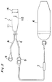
- Fig. 2 is a plan view of the self-administration device of Fig. 1 with a medical container connected thereto through a flow control means; and
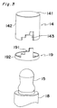
- Fig. 3 is an exploded perspective view illustrating a relationship between a dosage control means and a reservoir used in the self-administration device of Fig. 1;
- Fig. 4 is a schematic diagram illustrating changes of the pushed state of reservoir depressed by the pushing means when changing the engaging position of the annular member to the notched portion;
- Fig. 5 is cross sectional views of an apparatus of the prior art, illustrating operation of the apparatus.
- Referring now to Fig. 1, there is shown a self-administration device according to the present invention, which comprises a
cylindrical casing 11 provided at its closed end with adrug inflow port 12 and a drug outflow port 13, areservoir 15 housed in thecasing 11, a pushingmeans 14 provided at an open end of thecasing 11, and a dosage control means for adjusting a moving length of the pushing means 14 to several steps. Theinflow port 12 and outflow port 13 of thecasing 11 is opened to an interior of thereservoir 15. This device is so designed that, when thepushing means 14 is pressed by the patient, thepushing means 14 is moved by a distance determined by the dosage control means and thereservoir 15 is depressed and deformed by thepushing means 14, thereby delivering the liquid drug in thereservoir 15 to the outside of thereservoir 15. The dosage of the liquid drug is determined by the moving distance of the pushing means 14. - The
casing 11 is a cylindrical member opened at one end but closed at the other end and generally made of a transparent synthetic resin such as polyethylene, polypropylene, polyester or the like. The close end of thecasing 11 is provided with thedrug inflow port 12 and the drug outflow port 13. Although the closed end of thecasing 11 may be formed as an integral part of thecasing 11, it is preferred to form it as a separate member as shown in Fig. 1 so that thereservoir 15 and astop valve 16 can be assembled in the casing with ease. - In the embodiment of Fig. 1, the
casing 11 is composed of a cylindrical member with a stepped lumen, i.e., a large-sized lumen and a small-sized lumen, and aclosing member 18 fitted in the large-sized lumen of thecasing 11 and seated on the stepped wall of the large-sized lumen. The small-sized lumen of thecasing 11 is used as aninsertion hole 111 for attachment oftubes closing member 18 is shaped in the form of a disk and provided at its one flat end with a projection or port-formingportion 181 having thedrug inflow port 12 and the drug outflow port 13. Theclosing member 18 is so arranged in the large-sized lumen of thecasing 11 that the port-formingportion 181 is directed to the open end of thecasing 11. The opposite side of theclosing member 18 facing to theinsertion hole 111 is provided with ahole 183 for communication of thedrug inflow port 12 to anupstream drug tube 2, and ahole 184 for communication of the drug outflow port 13 to adownstream drug tube 4. As illustrated in Fig. 1, there may be provided acheck valve 16 in thehole 184 to prevent the liquid from flowing in the reverse direction. - The port-forming
portion 181 of theclosing member 18 is provided with anannular rib 182 at its distal end to prevent thereservoir 15 from slipping out of place. The closed end of thecasing 11 may be provided with projections (not illustrated in the drawings) for attachment of theupstream drug tube 2 anddownstream drug tube 4, instead of provision oftube insertion hole 111. - The
check valve 16 is provided for prevention of back flow of the liquid drug from thedownstream drug tube 4 toward thereservoir 15. Thecheck valve 16 is generally located, as illustrated in Fig. 1, in thehole 184 of theclosing member 18 and fixed thereto by aholding member 17 having a connectingend 171 to which thedownstream tube 4 is connected. The preferred check valve is of a duck bill type or of a ball valve type, though the check valve is not limited thereto. Thecheck valve 16 is not necessarily provided in the device body 1 and may be arranged in thedownstream drug tube 4 or in a Lure connecter 5. - The
reservoir 15 is attached to the port-formingportion 181 of theclosing member 18 and thus thedrug inflow port 12 and drug outflow port 13 are opened to thereservoir 15. Thereservoir 15 is prevented by theannular rib 182 from slipping out of place. Thereservoir 15 is a container for reserving a liquid drug fed from themedical container 6 and is easily deformable by pressure and has the ability to restore to its original shape. Thereservoir 15 is generally made of an elastic material such as flexible resin, natural rubbers, or synthetic rubbers to give it flexibility and restoring force. The preferred flexible resin includes polyethylene, polypropylene, polyester and the like, while the synthetic rubbers includes silicone rubber, olefine elastomers and the like. - The pushing
means 14 is generally made of synthetic resin such as polyethylene, polypropylene or polyester in the form of a bottom-closed cylindrical member composed of abottom 140 and acylindrical side wall 142. As shown in Fig. 1, the pushingmeans 14 is provided on itsinner bottom wall 140 with aprojection 141 to make it easy to push or depress thereservoir 15. The pushing means 14 is fitted in the large-sized lumen of thecasing 11 like as a nest. The pushing means 14 is movable along the inner wall of thecasing 11 to depress thereservoir 15 at the inner wall of the bottom 140. - Adjacent to the closing
member 18 there is provided anannular member 19. As best shown in Fig. 3, theannular member 19 is composed of anannular base portion 192 and a stepped engagingportion 191 and arranged coaxially and rotatably on the closingmember 18 so that the stepped engagingportion 191 is directed toward thereservoir 15. Thisannular member 19 constitutes dosage control means in cooperation with a steppednotch 143 provided in the side wall of the pushingmeans 14. The steppednotch 143 of the pushingmeans 14 is formed into a configuration complementary to the stepped engagingportion 191 of theannular member 19 and engages therewith in various forms, for example, in four forms as illustrated in Fig. 4. In Fig. 4B, the steppednotch 143 of the pushingmeans 14 is engaged at its all steps with the steps of the stepped engagingportion 191, while in Fig. 4E the steppednotch 143 of the pushingmeans 14 is engaged with the step of the stepped engagingportion 191 at its only one step or end. - The engagement between the stepped engaging
portion 191 and the steppednotch 143 is selected by turning theannular member 19 coaxial with thecasing 11 on its axis. In order to make it possible to turn theannular member 19 on its axis, the embodiment of Fig. 1, the side wall of thecasing 11 is provided with acircumferencial slit 112 at the position corresponding to that of theannular base portion 192 of theannular member 19 so that a pin or a suitable tool (not illustrated in the drawings) can be inserted from the outside into theslit 112. Theannular member 19 may be tuned on its axis coaxial with thecasing 11 by any suitable operating means, for example, by operating a knob or a projection (not illustrated in the drawings) provided on theannular member 19 and extending outward through theslit 112 so as to be operated by the finger. - The self-administration device is completed by connecting the
upstream drug tube 2 anddownstream drug tube 4 to the device body 1. Thesetubes Lure connector 3, 5 illustrated in Fig. 1, for connection to other devices. The self-administration device may have aliquid drug container 6 connected thereto directly or through a flow control means 7, as illustrated in Fig. 2. As theliquid drug container 6 to be connected to the self-administration device of the present invention, are those including a balloon, such as disclosed in Japanese examined publication Nos. 6-77604 and 6-83725 (which corresponds to U.S. patent 5178610. The self-administration device of the present invention may be used by directly connecting it the dropper of an infusion set. - As mentioned above, the self-administration device of the present invention is easy to operate, takes a short time for recharging the reservoir with the liquid drug, and makes it possible to control the dose of the liquid drug, and free from troubles such as leakage. Thus, it is suitable for administration of a liquid drug to a patient by one shot. Further, it is inexpensive, thus making it possible to reduce a charge to the patient.
Claims (2)
- A self-administration device comprising:a cylindrical casing opened at one end but closed at the opposite end, said closed opposite end being provided with a drug inflow port and a drug outflow port;an easily deformable and restorable reservoir housed in said casing and held by the closed end of said casing;pushing means provided at the open end of said casing and being movable along an inner wall of said casing to exert a pressure on said reservoir; andcontrol means for adjusting a moving distance of said pushing means to control a dosage of a liquid drug, said inflow port and outflow port of said casing being opened to the interior of said reservoir.
- The self-administration device according to claim 1, wherein said pushing means consists of a bottom-closed cylindrical member having a projection provided on its inner bottom wall, wherein the dosage control means comprises an annular member having a step-formed engaging portion provided adjacent to the closed end of the casing and a notched portion formed in the side wall of the pushing means so that it engages with the engaging portion of the annular member, and wherein the casing is provided with a slit giving access to the annular member to turn it around its axis.
Applications Claiming Priority (3)
| Application Number | Priority Date | Filing Date | Title |
|---|---|---|---|
| JP10124196A JP3147347B2 (en) | 1996-04-23 | 1996-04-23 | Chemical self-injection tool |
| JP10124196 | 1996-04-23 | ||
| JP101241/96 | 1996-04-23 |
Publications (3)
| Publication Number | Publication Date |
|---|---|
| EP0803260A2 true EP0803260A2 (en) | 1997-10-29 |
| EP0803260A3 EP0803260A3 (en) | 1998-03-04 |
| EP0803260B1 EP0803260B1 (en) | 2002-08-21 |
Family
ID=14295415
Family Applications (1)
| Application Number | Title | Priority Date | Filing Date |
|---|---|---|---|
| EP97106462A Expired - Lifetime EP0803260B1 (en) | 1996-04-23 | 1997-04-18 | Self-administration device for liquid drugs |
Country Status (4)
| Country | Link |
|---|---|
| US (1) | US5891102A (en) |
| EP (1) | EP0803260B1 (en) |
| JP (1) | JP3147347B2 (en) |
| DE (1) | DE69714809T2 (en) |
Cited By (5)
| Publication number | Priority date | Publication date | Assignee | Title |
|---|---|---|---|---|
| EP0941741A2 (en) * | 1998-02-27 | 1999-09-15 | Nissho Corporation | Self-administration device for liquid medicines |
| EP1812096A2 (en) * | 2004-11-19 | 2007-08-01 | Curlin Medical Inc. | Controlled-volume infusion device |
| EP2039381A1 (en) * | 2006-07-11 | 2009-03-25 | Tsukada Medical Research | Continuous drug solution infusion device |
| EP2083800A4 (en) * | 2006-10-19 | 2016-10-12 | Ambu As | Device and method for patient activated bolus administration |
| CN109908426A (en) * | 2019-03-12 | 2019-06-21 | 赵雁 | A kind of hemodialysis unit infusion apparatus |
Families Citing this family (19)
| Publication number | Priority date | Publication date | Assignee | Title |
|---|---|---|---|---|
| DE19821934C1 (en) * | 1998-05-15 | 1999-11-11 | Disetronic Licensing Ag | Device for the dosed administration of an injectable product |
| JP3588554B2 (en) * | 1998-10-23 | 2004-11-10 | オーベクス株式会社 | Liquid supply device |
| DE19900792C1 (en) * | 1999-01-12 | 2000-06-15 | Disetronic Licensing Ag | Injection unit forming part of e.g. pen-type self-injection syringe has continuous dosing stop in spiral form with constant pitch ensuring close fine control and accuracy in use |
| US6475188B1 (en) * | 1999-05-20 | 2002-11-05 | Anthony David Baxter | Bilateral microinjector pump for freely moving animals in an operant chamber |
| EP1153624B1 (en) * | 1999-07-29 | 2005-01-12 | Tsukada Medical Research Co., Ltd. | Portable pain relieving device |
| CN100402100C (en) | 2001-06-01 | 2008-07-16 | 艾佛罗公司 | Large volume bolus device and method |
| US6936035B2 (en) | 2002-12-31 | 2005-08-30 | I-Flow Corporation | Patient controlled drug administration device |
| KR100640952B1 (en) * | 2004-12-29 | 2006-11-02 | 동부일렉트로닉스 주식회사 | method for forming metal line of semiconductor device |
| US7914436B1 (en) | 2006-06-12 | 2011-03-29 | Abiomed, Inc. | Method and apparatus for pumping blood |
| JP5517029B2 (en) * | 2009-03-25 | 2014-06-11 | ニプロ株式会社 | Chemical self-injection device |
| JP5550638B2 (en) * | 2009-04-21 | 2014-07-16 | テルモ株式会社 | Medical container |
| WO2011034516A1 (en) | 2009-09-15 | 2011-03-24 | Becton, Dickinson And Company | Self-injection device |
| US8814829B2 (en) | 2010-08-12 | 2014-08-26 | Baxter International Inc. | Drug delivery device for fluid restricted patients |
| US8308688B2 (en) | 2010-12-15 | 2012-11-13 | Kimberly-Clark Worldwide, Inc | Large-volume bolus patient controlled drug administration device |
| US9061100B2 (en) | 2013-10-11 | 2015-06-23 | Avent, Inc. | Large-volume bolus patient controlled drug administration device with lock-out |
| KR101667192B1 (en) * | 2015-02-27 | 2016-10-18 | (주)이화바이오메딕스 | Liquid medicine infuser and liquid medicine supply device including the same |
| EP3474925B1 (en) | 2016-06-24 | 2021-03-17 | Avent, Inc. | Bolus refill indicator |
| KR102491623B1 (en) * | 2019-11-01 | 2023-01-27 | 김용현 | Medicinal liquid supply regulating apparatus, reservoir assembly for medicinal liquid supply regulating apparatus, medicinal liquid injection apparatus including the same |
| IL292621A (en) * | 2019-11-01 | 2022-07-01 | Yong Hyun Kim | Medicinal liquid pushing apparatus and medicinal liquid injection apparatus including same |
Citations (6)
| Publication number | Priority date | Publication date | Assignee | Title |
|---|---|---|---|---|
| US3400716A (en) * | 1964-06-05 | 1968-09-10 | William H. Schultz | Multiple dosage hypodermic syringe |
| AU5897973A (en) * | 1973-08-28 | 1975-02-13 | Murdoch C A | Dispensing means for liquid or pasty substances |
| WO1987000758A1 (en) * | 1985-08-06 | 1987-02-12 | Baxter Travenol Laboratories, Inc. | Patient-controlled delivery of beneficial agents |
| EP0413069A1 (en) * | 1989-08-15 | 1991-02-20 | Imed Corporation | Dual chamber pumping apparatus |
| WO1991008002A1 (en) * | 1989-12-05 | 1991-06-13 | Prime Medical Products, Inc. | Self-driven pump device |
| EP0744182A2 (en) * | 1995-05-24 | 1996-11-27 | Nissho Corporation | Self-administration device for liquid drugs |
Family Cites Families (2)
| Publication number | Priority date | Publication date | Assignee | Title |
|---|---|---|---|---|
| US2849159A (en) * | 1955-07-18 | 1958-08-26 | Marshfield Mfg Company | Solenoid-actuated dispenser |
| GB8615437D0 (en) * | 1986-06-24 | 1986-07-30 | Bard Ltd | Pump |
-
1996
- 1996-04-23 JP JP10124196A patent/JP3147347B2/en not_active Expired - Fee Related
-
1997
- 1997-04-09 US US08/835,571 patent/US5891102A/en not_active Expired - Lifetime
- 1997-04-18 EP EP97106462A patent/EP0803260B1/en not_active Expired - Lifetime
- 1997-04-18 DE DE69714809T patent/DE69714809T2/en not_active Expired - Lifetime
Patent Citations (6)
| Publication number | Priority date | Publication date | Assignee | Title |
|---|---|---|---|---|
| US3400716A (en) * | 1964-06-05 | 1968-09-10 | William H. Schultz | Multiple dosage hypodermic syringe |
| AU5897973A (en) * | 1973-08-28 | 1975-02-13 | Murdoch C A | Dispensing means for liquid or pasty substances |
| WO1987000758A1 (en) * | 1985-08-06 | 1987-02-12 | Baxter Travenol Laboratories, Inc. | Patient-controlled delivery of beneficial agents |
| EP0413069A1 (en) * | 1989-08-15 | 1991-02-20 | Imed Corporation | Dual chamber pumping apparatus |
| WO1991008002A1 (en) * | 1989-12-05 | 1991-06-13 | Prime Medical Products, Inc. | Self-driven pump device |
| EP0744182A2 (en) * | 1995-05-24 | 1996-11-27 | Nissho Corporation | Self-administration device for liquid drugs |
Cited By (10)
| Publication number | Priority date | Publication date | Assignee | Title |
|---|---|---|---|---|
| EP0941741A2 (en) * | 1998-02-27 | 1999-09-15 | Nissho Corporation | Self-administration device for liquid medicines |
| EP0941741A3 (en) * | 1998-02-27 | 2000-04-12 | Nissho Corporation | Self-administration device for liquid medicines |
| EP1812096A2 (en) * | 2004-11-19 | 2007-08-01 | Curlin Medical Inc. | Controlled-volume infusion device |
| EP1812096A4 (en) * | 2004-11-19 | 2008-06-04 | Curlin Medical Inc | Controlled-volume infusion device |
| US8372045B2 (en) | 2004-11-19 | 2013-02-12 | Curlin Medical Inc. | Controlled-volume infusion device |
| EP2039381A1 (en) * | 2006-07-11 | 2009-03-25 | Tsukada Medical Research | Continuous drug solution infusion device |
| EP2039381A4 (en) * | 2006-07-11 | 2012-07-18 | Tsukada Medical Res Co Ltd | Continuous drug solution infusion device |
| EP2083800A4 (en) * | 2006-10-19 | 2016-10-12 | Ambu As | Device and method for patient activated bolus administration |
| CN109908426A (en) * | 2019-03-12 | 2019-06-21 | 赵雁 | A kind of hemodialysis unit infusion apparatus |
| CN109908426B (en) * | 2019-03-12 | 2021-03-30 | 青岛市海慈医疗集团 | Infusion apparatus for hemodialysis room |
Also Published As
| Publication number | Publication date |
|---|---|
| JPH09285539A (en) | 1997-11-04 |
| EP0803260B1 (en) | 2002-08-21 |
| US5891102A (en) | 1999-04-06 |
| DE69714809D1 (en) | 2002-09-26 |
| EP0803260A3 (en) | 1998-03-04 |
| JP3147347B2 (en) | 2001-03-19 |
| DE69714809T2 (en) | 2003-04-10 |
Similar Documents
| Publication | Publication Date | Title |
|---|---|---|
| US5891102A (en) | Self-administration device for liquid drugs | |
| AU621750B2 (en) | Continuous/bolus infusor | |
| EP0231371B1 (en) | Patient-controlled delivery of beneficial agents | |
| US4544371A (en) | Implantable metered dose drug delivery system | |
| US4548607A (en) | Implantable manually actuated medication dispensing system | |
| US6213981B1 (en) | Self-administration device for liquid medicines | |
| EP0190477A1 (en) | Body mounted pump housing and pump assembly employing the same | |
| JPS61113469A (en) | Implantable drug administration assembly | |
| EP2233166A2 (en) | Self-administration device for liquid medicine | |
| EP0865795B1 (en) | Self-administration device for liquid drugs | |
| CA2750800C (en) | Medical fluid dispenser | |
| US20050234406A1 (en) | Patient-controlled analgesia (pca) apparatus capable of continuous injection and additional administration of drug solution | |
| EP0504255B1 (en) | Self-driven pump device | |
| US4710177A (en) | Subcutaneous ventricular injection apparatus and method | |
| EP0744182A2 (en) | Self-administration device for liquid drugs | |
| US11602595B2 (en) | Medical fluid injector including bolus counter | |
| JP3721777B2 (en) | Chemical solution self-injection set | |
| EP0245056A1 (en) | Ambulatory disposable infusion pump | |
| CA1245930A (en) | Body mounted pump housing and pump assembly employing the same | |
| WO2005089836A2 (en) | Apparatus and method for dispensing a liquid |
Legal Events
| Date | Code | Title | Description |
|---|---|---|---|
| PUAI | Public reference made under article 153(3) epc to a published international application that has entered the european phase |
Free format text: ORIGINAL CODE: 0009012 |
|
| AK | Designated contracting states |
Kind code of ref document: A2 Designated state(s): DE FR GB IT |
|
| PUAL | Search report despatched |
Free format text: ORIGINAL CODE: 0009013 |
|
| AK | Designated contracting states |
Kind code of ref document: A3 Designated state(s): DE FR GB IT |
|
| 17P | Request for examination filed |
Effective date: 19980327 |
|
| 17Q | First examination report despatched |
Effective date: 20001201 |
|
| RAP1 | Party data changed (applicant data changed or rights of an application transferred) |
Owner name: NIPRO CORPORATION |
|
| GRAG | Despatch of communication of intention to grant |
Free format text: ORIGINAL CODE: EPIDOS AGRA |
|
| GRAG | Despatch of communication of intention to grant |
Free format text: ORIGINAL CODE: EPIDOS AGRA |
|
| GRAH | Despatch of communication of intention to grant a patent |
Free format text: ORIGINAL CODE: EPIDOS IGRA |
|
| GRAH | Despatch of communication of intention to grant a patent |
Free format text: ORIGINAL CODE: EPIDOS IGRA |
|
| GRAA | (expected) grant |
Free format text: ORIGINAL CODE: 0009210 |
|
| AK | Designated contracting states |
Kind code of ref document: B1 Designated state(s): DE FR GB IT |
|
| REG | Reference to a national code |
Ref country code: GB Ref legal event code: FG4D |
|
| REF | Corresponds to: |
Ref document number: 69714809 Country of ref document: DE Date of ref document: 20020926 |
|
| ET | Fr: translation filed | ||
| PLBE | No opposition filed within time limit |
Free format text: ORIGINAL CODE: 0009261 |
|
| STAA | Information on the status of an ep patent application or granted ep patent |
Free format text: STATUS: NO OPPOSITION FILED WITHIN TIME LIMIT |
|
| 26N | No opposition filed |
Effective date: 20030522 |
|
| PGFP | Annual fee paid to national office [announced via postgrant information from national office to epo] |
Ref country code: DE Payment date: 20120425 Year of fee payment: 16 |
|
| PGFP | Annual fee paid to national office [announced via postgrant information from national office to epo] |
Ref country code: FR Payment date: 20120504 Year of fee payment: 16 Ref country code: GB Payment date: 20120418 Year of fee payment: 16 |
|
| PGFP | Annual fee paid to national office [announced via postgrant information from national office to epo] |
Ref country code: IT Payment date: 20120421 Year of fee payment: 16 |
|
| GBPC | Gb: european patent ceased through non-payment of renewal fee |
Effective date: 20130418 |
|
| PG25 | Lapsed in a contracting state [announced via postgrant information from national office to epo] |
Ref country code: GB Free format text: LAPSE BECAUSE OF NON-PAYMENT OF DUE FEES Effective date: 20130418 Ref country code: DE Free format text: LAPSE BECAUSE OF NON-PAYMENT OF DUE FEES Effective date: 20131101 |
|
| REG | Reference to a national code |
Ref country code: FR Ref legal event code: ST Effective date: 20131231 |
|
| REG | Reference to a national code |
Ref country code: DE Ref legal event code: R119 Ref document number: 69714809 Country of ref document: DE Effective date: 20131101 |
|
| PG25 | Lapsed in a contracting state [announced via postgrant information from national office to epo] |
Ref country code: FR Free format text: LAPSE BECAUSE OF NON-PAYMENT OF DUE FEES Effective date: 20130430 Ref country code: IT Free format text: LAPSE BECAUSE OF NON-PAYMENT OF DUE FEES Effective date: 20130418 |