EP0802462B1 - Method of making two cards inter-lock antiforgery marks - Google Patents
Method of making two cards inter-lock antiforgery marks Download PDFInfo
- Publication number
- EP0802462B1 EP0802462B1 EP95928397A EP95928397A EP0802462B1 EP 0802462 B1 EP0802462 B1 EP 0802462B1 EP 95928397 A EP95928397 A EP 95928397A EP 95928397 A EP95928397 A EP 95928397A EP 0802462 B1 EP0802462 B1 EP 0802462B1
- Authority
- EP
- European Patent Office
- Prior art keywords
- inspecting
- mark
- card
- identifying
- double
- Prior art date
- Legal status (The legal status is an assumption and is not a legal conclusion. Google has not performed a legal analysis and makes no representation as to the accuracy of the status listed.)
- Expired - Lifetime
Links
Images



Classifications
-
- G—PHYSICS
- G03—PHOTOGRAPHY; CINEMATOGRAPHY; ANALOGOUS TECHNIQUES USING WAVES OTHER THAN OPTICAL WAVES; ELECTROGRAPHY; HOLOGRAPHY
- G03H—HOLOGRAPHIC PROCESSES OR APPARATUS
- G03H1/00—Holographic processes or apparatus using light, infrared or ultraviolet waves for obtaining holograms or for obtaining an image from them; Details peculiar thereto
- G03H1/04—Processes or apparatus for producing holograms
- G03H1/0402—Recording geometries or arrangements
- G03H1/041—Optical element in the object space affecting the object beam, not otherwise provided for
-
- G—PHYSICS
- G03—PHOTOGRAPHY; CINEMATOGRAPHY; ANALOGOUS TECHNIQUES USING WAVES OTHER THAN OPTICAL WAVES; ELECTROGRAPHY; HOLOGRAPHY
- G03H—HOLOGRAPHIC PROCESSES OR APPARATUS
- G03H1/00—Holographic processes or apparatus using light, infrared or ultraviolet waves for obtaining holograms or for obtaining an image from them; Details peculiar thereto
- G03H1/04—Processes or apparatus for producing holograms
- G03H1/08—Synthesising holograms, i.e. holograms synthesized from objects or objects from holograms
-
- G—PHYSICS
- G06—COMPUTING OR CALCULATING; COUNTING
- G06K—GRAPHICAL DATA READING; PRESENTATION OF DATA; RECORD CARRIERS; HANDLING RECORD CARRIERS
- G06K19/00—Record carriers for use with machines and with at least a part designed to carry digital markings
- G06K19/06—Record carriers for use with machines and with at least a part designed to carry digital markings characterised by the kind of the digital marking, e.g. shape, nature, code
- G06K19/08—Record carriers for use with machines and with at least a part designed to carry digital markings characterised by the kind of the digital marking, e.g. shape, nature, code using markings of different kinds or more than one marking of the same kind in the same record carrier, e.g. one marking being sensed by optical and the other by magnetic means
- G06K19/10—Record carriers for use with machines and with at least a part designed to carry digital markings characterised by the kind of the digital marking, e.g. shape, nature, code using markings of different kinds or more than one marking of the same kind in the same record carrier, e.g. one marking being sensed by optical and the other by magnetic means at least one kind of marking being used for authentication, e.g. of credit or identity cards
- G06K19/16—Record carriers for use with machines and with at least a part designed to carry digital markings characterised by the kind of the digital marking, e.g. shape, nature, code using markings of different kinds or more than one marking of the same kind in the same record carrier, e.g. one marking being sensed by optical and the other by magnetic means at least one kind of marking being used for authentication, e.g. of credit or identity cards the marking being a hologram or diffraction grating
Definitions
- the present invention relates to an anti-counterfeit method using a double-card track laser hologram anti-counterfeit mark.
- Color fabric thread is dispersed and processed first and then added into the paper pulp-making system for producing paper material contained color fabric thread.
- a kind of paper with uniform-distributed color fabric thread on its surface is manufactured.
- the feature of presenting clear and uniform color fabric thread differs from that of ordinary printing paper.
- the anti-counterfeit purpose can be achieved by using such kind of paper.
- the embossed hologram is duplicated on a piece of thermoplastic paper with aluminium film by die pressing for manufacturing the laser hologram anti-counterfeit identification mark.
- the rainbow hologram used to be in vogue for a time and considered as the most effective way for anti-counterfeit identification.
- the infringers had succeeded to imitate the above-mentioned laser hologram anti-counterfeit identification marks and used them as real certificate of their false products, causing heavy losses to manufactures of famous trademark products and consumers.
- a Chinese patent application No. 87205139 published on Nov. 16,1988, and in a Canadian patent application with publication date Nov. 9, 1984 and filing No.
- identification marks should possess the following features: 1.The self-protecting function, e.g. to prove the authenticity of themselves before testifying the protected objects; 2. The impossibility to be copied; 3.The identifying capability under their various changeable circumstances; 4.The simple and definite method for checking their authenticity; 5.The one-off feasibility and reasonable cost for mass production.
- the present invention provides:
- the general technical solution of the invention is to make at least two identifying marks R and T and to make corresponding two inspecting marks R' and T' on a first and a second identifying card and on a first and second inspecting card, respectively.
- the use of charged particle track, laser speckles and optical information processing technique makes R, T and R', T' impossible to reproduce.
- R card coincides with R', T coincides with T' a prefixed information comes out under illumination of white light or laser beam.
- R coincides with R' a relatively fixed information appears, proving the reality of the mark itself.
- the second identifying mark T coincides with the second inspecting mark T', very different special information arises, proving the reality of protected objects. In this way the object of the present invention is achieved.
- Said image original may be any known picture, for example character, sign and so on, or any randomly produced pictures as laser speckles, charged particle tracks and etc. , or the combination of the above mentioned images, for example nuclear tracks added to a predetermined image original.
- Said identifying cards and inspecting cards appear in pairs. In case of more than one pair, they may be composed of double- card master masks of space domain or spectrum domain separately of their combination. Among them the inspecting cards can be presented in the form of computer software. The amount of pairs of identifying and inspecting cards depends on anti-counterfeit requirements for forming R - R' cards, T - T' cards and so on. These cards may be operated simultaneously or switched on successively by interlock for realizing multiple inspections.
- An inspecting apparatus for said double-card track laser hologram anti-counterfeit identification mark includes a light source, an identifying card base and an inspecting card base with location function, an imaging system and a photo-electronic converting unit, a testing probe and a processor connected to the testing probe.
- the imaging system consisting of optical devices fitted in conversions of the identifying card and inspecting card possesses an inspecting screen for observing the results directly or can operate directly on the photo-electronic converter.
- the processor is connected to the photo- electronic unit and is controlled by the identifying program of the electronic identifying system.
- the schematic diagram for the inspecting apparatus the structure of the optical system for the combination of identifying card with inspecting card is shown.
- It includes a double-arm dark box and an optical system, constructed by a light source, an expanding lens, and a collimation lens.
- a reflection frame is installed, to which R' base, T' base and R, T bases are mounted.
- a Fourier lens and an inspecting screen for observing information image are installed in a distance of the focus length of the Fourier lens.
- On the reflection frame pressing chip is mounted. When the pressing chip is pushed down on the identification mark, the location function is completed through adjusting the setting screw mounted on the chip to fix on the setting sign of the anti-counterfeit identification mark.
- the identifying card base and the inspecting card base consist of miniature physico-chemical materials.
- the setting function is realized through physico-chemical reaction of the identifying card base and the inspecting card base together with the setting sign of the identifying card and inspecting card.
- Inspecting card R' is sealed in a device made of transparent material with a dismount-proof base plate, which consists of a dismount proof screw, a pair of springs, a pair of pipes with open upper ends, and a pair of sliding-vanes, being able to slide in the pipes.
- a dismount-proof base plate which consists of a dismount proof screw, a pair of springs, a pair of pipes with open upper ends, and a pair of sliding-vanes, being able to slide in the pipes.
- an inspecting screen of said inspecting apparatus is connected to a computer and relevant control programs are completed.
- the operation procedure of said double-card track laser hologram anti-counterfeit marks is as follows:
- the first inspecting card carrying R' mark is sealed in the inspecting apparatus when the latter is manufactured, the inspecting mark R' is used for protecting anti-counterfeit identification marks themselves;
- the second inspecting card carrying T' mark changes together with the protected object for proving the reality of commodity, ticket, certificate or bank note.
- the incident light illuminates the cards carrying the R',T', R, T marks at the same time, and the reflection light passes through the Fourier transformation lens and causes reconstructed images R'R and T'T on the observation screen.
- the two reconstructed images can be made more, and it is also possible to display, reconstructed images directly.
- the coincidence of R mark with R' mark proves the reality of marks themselves and the coincidence of T mark with T' mark proves the reality of the protected object.
- the method provides the state's administrative departments with a powerful means for identifying the reality of commodity.
- the first inspecting card carrying R' mark together with the inspecting apparatus are used to prove the reality of the first anti-counterfeit identification card carrying/ R identification mark and the protected object to prove the reality of the inspecting apparatus and R' card.
- the correspondence of the T' mark with the T mark is adopted for proving the reality of the object to be protected.
- the present embodiment illustrates a method for producing a CGH identification card and an inspecting card carrying a first identifying and inspecting mark, respectively by using picture-separating method.
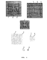
- Fig. 1 is a schematic drawing showing the production of CGH double-card master mask by using picture-separating method.
- a rainbow hologram is made on a photoresist plate.
- One of the double-card master masks (9) is transferred to a photoresist plate as master mask for the first identifying mark R.
- the other card of the double-card master masks is transferred to another photoresist plate for making a master mask for the first inspecting mark R'.
- Processed by available technology, such as developing, washing, electromoulding and die pressing two cards are obtained respectively carrying the first identification mark R and the first inspecting mark R'.
- the R' mark-carrying card is solidified in the inspecting apparatus and the other card carrying the identification mark R should be pasted on the protected objects.
- This embodiment illustrates manufacturing technology of CGH anti-counterfeit identification card and inspecting card by using random sampling on frequency spectrum plane.
- Fig. 2 is a schematic drawing showing the CGH double-card master mask by random sampling on frequency spectrum plane.
- Original picture (11) Every small square is considered as a sampling unit (12), the sampling point (13) is chosen at the top point of the square.
- Assignment to letter 'E' is as follows: value '1' is given to the sampling points inside the picture and value '0' outside the picture. So a real matrix A(11) is obtained.
- a computer program has been developed for controlling computerized plotting.
- the sampling interval is ⁇ with a small rectangle plotted in each sampling cell.
- Two identical holograms (14) and (15) are printed. Then 2000 rectangles randomly distributed on the hologram (14) are painted with white correction fluid, on the hologram (15) the rest 2096 rectangles are crossed out. Finally, the two pictures are reduced by a microphotography on a photo negative for getting the double-card master masks (17) and (18) in the size of 2.4 x 2.4mm 2 .
- the double-card master masks (9) and (10) in embodiment 1 are used for making the two cards carrying the first identification mark R and the first inspecting mark R', respectively and two cards carrying a second identification mark T and a second inspecting mark T', respectively are made in the same manner by using double card master masks (17) and (18).
- the card carrying the first inspecting mark R' is installed in the inspecting apparatus and the card carrying the second inspecting mark T' is kept by the operator.
- the images of the first and second identifying marks R and T are potentialized in form of an ordinary rainbow laser hologram.
- the operator first inserts the card with the second inspecting mark T' into the apparatus, and then direct the tester probe to the anti-counterfeit identification marks R and T.
- the coincidence of mark R with mark R' gives a fixed message to prove the truthfulness of the identification mark
- the coincidence of T with T gives a preset message to certify the authenticity of the protected object.
- Fig. 3 is a schematic drawing for CGH double-card master mask by means of laser speckles.
- a Fourier lens (19) is put vertically in the way of parallel laser beam, a nuclear track picture (20) is located at the back focus plane of the Fourier lens (19) , and a photographic film is placed at a distance of 10 cm from the nuclear track picture (20).
- a glass plate with an opaque information picture * (21) is pasted.
- a negative (22) recording laser speckles and information is obtained.
- Both positive (23) and negative (22) have the same dimension of 4 x 4cm 2 .
- Positive (23) and negative (22) are enlarged separately by magnifying device and the magnified images are projected on coordinate paper with 128 x 128 small squares as sampling cells (24).
- the top points of the small squares are sampling points (25), and the positive (23) and negative (22) are assigned according to their transparency.
- Value of "1” is assigned to the sampling points in the transparent part and "0" is assigned to the sampling points in the opaque part.
- values of depth are assigned by computer.
- the double-card master masks (28) and (29) are used for making double-card carrying the second identifying and inspecting marks T and T', respectively.
- the manufacturing procedure is the same as in embodiment 2.
- Fig. 4 is a schematic drawing showing the nuclear track laser hologram double-card master mask made by CGH method.
- Charged particles produced by accelerator or spontaneous fission fragments from natural uranium are used to irradiate polycarbonate film of 50 ⁇ thickness.
- the ratio between the area with track and that without track is 1:1.
- irradiated polycarbonate film is etched in KOH solution of 6.5 N at 70°C for 60 minutes. The etched film is washed and dried by air and serves as track original (30).
- Another polycarbonate film of 50 ⁇ thickness is etched as a pattern of "Double dragon" leakage mask (32) which is put between said charged particle source and another identical polycarbonate film.
- a "double dragon" pattern consisting of tracks is produced as information track negative (31).
- the information track positive (33) is formed by exposing once track original (30) overlapped by information track negative (31).
- Computer and special purpose program are used for micrographic scanning, depth assignment, FFT for track original (30) and information track positive (33), and double-card track master masks (36) and (37) are plotted by computer (in which sampling cells (34) and sampling points (35) are treated as in embodiment 1).
- the double-card track master masks (36) and (37) are reduced for making two pair double-card master masks (38) and (39) with the help of a microscopy device.
- the double-card master masks (38) and (39) are used for making double-card T, T'.
- the manufacturing procedure is the same as in embodiment 3.
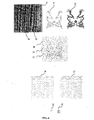
- Fig. 5 shows schematic drawing of double-card track laser hologram anti-counterfeit identification mark and its corresponding inspecting mark.
- Fig. 6 shows schematic drawing of an optical system for inspecting double-card track laser hologram anti-counterfeit identification mark.
- a special plate-making technology of microelectronics is applied to the normalized matrixes B 4 and B 5 .
- the background data units (40) every small rectangle corresponding to the matrix element in each sampling cell is exposed one by one by electron beam and then exactly reduced for forming CGH double-card master masks (41) and (43).
- a special microelectronic technology for making plates is applied to the complex matrixes B 22 and B 23 in the same way, every small rectangle corresponding to the matrix element in each sampling cell is exposed one by one under electron beam and then exactly reduced for getting CGH double-card master masks (42) and (44) and "true or false" of the cards can be checked on the inspecting optical system of Fig.6.
- the dark box(50) is divided into two parts in the directions of incident light from the light source(49) and reflection light. Behind the light source (49), an expanding lens (51) and a collimation lens (52) are installed. A reflector support (53), R' base (54), T base (55) and RT base (56) are mounted on the top of the dark box (50). On the R' base (54), the double-card master mask (41) is placed, on the T' base (55) -- the double-card master mask(42), on the RT base(56) -- double-card master masks (43) and (44). In the dark box(50) a Fourier lens (57) and an observation screen (58) for watching image are installed in the direction of reflection light.
- a semitransparent-semireflection glass(59) is mounted, on the reflection support (53) a pressing chip (60), an adjusting screw (61) and a dismount-proof base bottom (62) are mounted.
- the dismount-proof base bottom (62) consists of a dismount-proof screw (63), a pair of spring (64), a pipe (65) with upper open mouth and a pair of sliding blades (66) being able to slide in pipe.
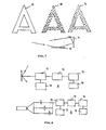
- Fig. 7 shows a schematic drawing for producing double-leakage-mask track laser hologram anti-counterfeit identification mark.
- Fig. 8 shows a schematic drawing of the inspecting apparatus for the double-card track laser hologram anti-counterfeit identification mark.
- a letter 'A' is cut off in the middle of the polyester film of 100 ⁇ thickness, so the first leakage mask (68) is ready. Then a piece of polycarbonate film (PC) of 10 ⁇ thickness is overlapped behind the leakage mask (68) and irradiated by heavy ion beam for a certain time, after that the PC film of 10 ⁇ thickness is taken off and put into 70°C, 6.5 N KOH solution for preparing microhole film by etching, so the second leakage mask (69) is obtained.
- PC polycarbonate film
- Another polycarbonate film (PC) of 50 ⁇ thickness is placed behind the second leakage mask (69) and irradiated under Cf-252 source for a certain time, then the polycarbonate film of 50 ⁇ thickness is taken off and put into 70°C, 6.5 N KOH solution for etching for 60 minutes, after washing, cold drying and coloring, the double -track original (70) is prepared. Applying three-dimension hologram method the double-track original (70) is transferred to the photoetching master mask (71) storing the rainbow hologram information and after electromoulding turned into double-track laser anti-counterfeit identification card. At the same time the double-track original (70), saved in computer with the help of CCD and picture catching card, is served as double-track secondary original(70').
- double-track laser anti-counterfeit marks During inspection, light illuminates double-track laser anti-counterfeit marks, an image appears in the imaging system (72) located in the imaging direction, which can be observed by an observation system (73) or can be transformed in electronic image by photoelectric converter and input into computer (75), and compared with already stored double-track secondary original (70') in order to tell the true from the false and finally the result can be displayed on the monitor (76).
- double-track original (70) can be joined directly to developed photoresist stencil contained ordinary rainbow hologram information and then the double-track laser anti-counterfeit identification mark is produced by means of electromoulding.
- FIG.8B the reproducing and mixing process of the double-card track laser hologram anti-counterfeit identification card(46), card R'(47) and card T'(48) are shown by using parallel beam.
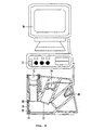
- Fig. 9 shows construction diagram of the inspecting apparatus for the double-card track laser hologram identification mark.
- An expanding lens is mounted in the front of the semiconductor laser device.
- a collimation lens ahead the expanding lens, a Fourier lens in the direction of diffraction and a CCD photoelectric converter (74) on the back focal plane of the Fourier lens are installed.
- the indication lamp (80) lights up through conducting wire(79) by help of the magnetic switch (78) on the testing probe.
- the information of the identification card and inspecting card captured and digitized by a picture capture card is input into computer (75), so as to be compared under the control of an identification program and the result of comparison is displayed on the monitor (76).
Landscapes
- Physics & Mathematics (AREA)
- General Physics & Mathematics (AREA)
- Engineering & Computer Science (AREA)
- Theoretical Computer Science (AREA)
- Holo Graphy (AREA)
- Credit Cards Or The Like (AREA)
- Length Measuring Devices By Optical Means (AREA)
Description
- The present invention relates to an anti-counterfeit method using a double-card track laser hologram anti-counterfeit mark.
- A lot of anti-counterfeit technologies such as techniques based on temperature alternation, fluorescence and phosphorescence, implicit metal, laser hologram and etc. have been developed for checking bank-note, paper money, bill and trade mark. On Oct. 16, 1991, a Chinese patent for invention (application No. 90105079.2) was disclosed, in which a method for producing a potential image in document was introduced. The potential image is inserted on a certain place of bank note or document, in case of necessity the potential image can be observed for identifying the genuineness. A method for producing a special kind of anti-counterfeit paper is disclosed in another Chinese patent published on Sept. 25, 1991 with application No. 91102676. Color fabric thread is dispersed and processed first and then added into the paper pulp-making system for producing paper material contained color fabric thread. Through paper machine, a kind of paper with uniform-distributed color fabric thread on its surface is manufactured. The feature of presenting clear and uniform color fabric thread differs from that of ordinary printing paper. The anti-counterfeit purpose can be achieved by using such kind of paper.
- In recent years a kind of laser holographic method for anti-counterfeit identification mark has been developed in trademark protection. The technical processes for photography, plate making, printing are described in the book "Practical Hologram Photography" published by the Publishing House of Beijing Institute of Posts and Telecommunications. A Chinese patent published on Sept. 27, 1989 with application No.87205319 has also described a laser hologram method for anti-counterfeit identification. The feature is at the first step an embossed white light reconstructed hologram is taken by using photoresist plate as recording medium and then the embossed image is transferred from the photoresist plate to a metallic plate by electric casting. Finally, a moulded master mask is obtained. The embossed hologram is duplicated on a piece of thermoplastic paper with aluminium film by die pressing for manufacturing the laser hologram anti-counterfeit identification mark. For its multicoloured diffraction effects, three-dimensional feeling, and difficulty to be copied, the rainbow hologram used to be in vogue for a time and considered as the most effective way for anti-counterfeit identification. However, the infringers had succeeded to imitate the above-mentioned laser hologram anti-counterfeit identification marks and used them as real certificate of their false products, causing heavy losses to manufactures of famous trademark products and consumers. In a Chinese patent application No. 87205139 published on Nov. 16,1988, and in a Canadian patent application with publication date Nov. 9, 1984 and filing No. 86132651 entitled "An apparatus for identifying real product by using optic interference and its production method", furthermore, in a German patent application No. 93168673 published on Feb. 29, 1992 entitled " Safe original document of credit card and ID card" , technical methods have been introduced by which a secured bar code mark or a difficult-to-copy safety layer is added to the anti-counterfeit identification marks for proving the authenticity of bank notes, tickets, documents and trademarks. In spite of the complicity of the techniques, the counterfeiters spare no expense to acquire and master them. Although the counterfeiters are not able to make the fake identification marks exactly as the real ones, the consumers can not distinguish the truth from the false for the unspecified information as fringes, fluorescent, magnetic granule and etc. because of their limited identifying ability. In order to achieve the exact anti-counterfeit goal, identification marks should possess the following features: 1.The self-protecting function, e.g. to prove the authenticity of themselves before testifying the protected objects; 2. The impossibility to be copied; 3.The identifying capability under their various changeable circumstances; 4.The simple and definite method for checking their authenticity; 5.The one-off feasibility and reasonable cost for mass production.
- It is an object of the present invention to provide an anti-counterfeit method using a double-card track laser hologram anti-counterfeit mark which utilize nuclear track, laser speckles and optical information processing technique or a combination thereof to implement a double-card, double protection technical scheme for the anti-counterfeit mark, wherein one card is an identification card and the other card is an inspecting card for proving the reality of the mark itself and of the object to be protected by said mark, wherein said anti-counterfeit method uses an inspecting apparatus for proving the reality of the mark itself on the basis of the first card and for proving the reality of the object to be protected by the mark by using the other card so as to get rid of the fake disturbance from imitators.
- The above object is solved in accordance with the enclosed claims.
- According to an essential aspect, the present invention provides:
- An anti-counterfeit method using a double-card track laser
hologram anti counterfeit mark to implement a double
card, double protection technical scheme, wherein one
card is an identifying card being attached on an object to
be protected and comprising a first identifying card carrying a first identifying mark and
a second identifying card carrying a second identifying mark and the other card comprises a first inspecting
card comprising a first inspecting mark sealed in
an inspecting apparatus and a second inspecting card carrying a second inspecting mark
kept by an operator, the method comprising the following
steps:
- I. producing the first identifying mark and the first
inspecting mark by means of:
- a. dividing an arbitrarily predetermined or randomly produced first original image or the spectrum thereof into two parts,
- b. using a computer generated hologram (hereafter referred to as the CGH method) to transform said two parts of the first original image to a first identifying master mask and a first inspecting master mask to produce different first photoresist plates; and
- c. making a first identifying card carrying said first identifying mark and a first inspecting card carrying said first inspecting mark by developing, electroforming and die pressing said different first photoresist plates separately;
- II. producing the second identifying mark and the second
inspecting mark by means of:
- a. using an arbitrarily predeterminded or randomly
produced second original image or the spectrum thereof,
then using the CGH method to transform the second original
image or the spectrum thereof into two identical holograms
and randomly processing these two holograms
into two complementary second identifying master mask
of said second identifying mark and second inspecting
master mask of said second inspecting mark to produce
different second photo resistive plates or
using an arbitrarily predeterminded or randomly produced second original image or the spectrum thereof, two complementary second original images are produced by image processing, then using the CGH method to transform said two complementary second original images respectively into two second identifying master mask of said second identifying mark and second inspecting master mask of said second inspecting mark to produce different second photo resist plates, - b. making a second identifying card and a second inspecting card by developing, electroforming and die pressing the different second photo resistive plates seperately;
- III. using the inspecting apparatus together with said identifying and inspecting cards a relatively fixed information appears proving the reality of the mark itself when the first identifying mark coincides with the first inspecting mark under illumination of white light or laser beam;
- IV. using said inspecting apparatus for producing very different special information proving the reality of the protected object, when the second identifying mark coincides with the second inspecting mark.
-
- The general technical solution of the invention is to make at least two identifying marks R and T and to make corresponding two inspecting marks R' and T' on a first and a second identifying card and on a first and second inspecting card, respectively. The use of charged particle track, laser speckles and optical information processing technique makes R, T and R', T' impossible to reproduce. When R card coincides with R', T coincides with T', a prefixed information comes out under illumination of white light or laser beam. When R coincides with R', a relatively fixed information appears, proving the reality of the mark itself. When the second identifying mark T coincides with the second inspecting mark T', very different special information arises, proving the reality of protected objects. In this way the object of the present invention is achieved.
- Said image original may be any known picture, for example character, sign and so on, or any randomly produced pictures as laser speckles, charged particle tracks and etc. , or the combination of the above mentioned images, for example nuclear tracks added to a predetermined image original. Said identifying cards and inspecting cards appear in pairs. In case of more than one pair, they may be composed of double- card master masks of space domain or spectrum domain separately of their combination. Among them the inspecting cards can be presented in the form of computer software. The amount of pairs of identifying and inspecting cards depends on anti-counterfeit requirements for forming R - R' cards, T - T' cards and so on. These cards may be operated simultaneously or switched on successively by interlock for realizing multiple inspections.
- An inspecting apparatus for said double-card track laser hologram anti-counterfeit identification mark includes a light source, an identifying card base and an inspecting card base with location function, an imaging system and a photo-electronic converting unit, a testing probe and a processor connected to the testing probe. In the apparatus the imaging system consisting of optical devices fitted in conversions of the identifying card and inspecting card possesses an inspecting screen for observing the results directly or can operate directly on the photo-electronic converter. The processor is connected to the photo- electronic unit and is controlled by the identifying program of the electronic identifying system. In the schematic diagram for the inspecting apparatus the structure of the optical system for the combination of identifying card with inspecting card is shown. It includes a double-arm dark box and an optical system, constructed by a light source, an expanding lens, and a collimation lens. At the end of the dark box, a reflection frame is installed, to which R' base, T' base and R, T bases are mounted. In the light reflection direction of the dark box, a Fourier lens and an inspecting screen for observing information image are installed in a distance of the focus length of the Fourier lens. On the reflection frame pressing chip is mounted. When the pressing chip is pushed down on the identification mark, the location function is completed through adjusting the setting screw mounted on the chip to fix on the setting sign of the anti-counterfeit identification mark. The identifying card base and the inspecting card base consist of miniature physico-chemical materials. The setting function is realized through physico-chemical reaction of the identifying card base and the inspecting card base together with the setting sign of the identifying card and inspecting card.
- Inspecting card R' is sealed in a device made of transparent material with a dismount-proof base plate, which consists of a dismount proof screw, a pair of springs, a pair of pipes with open upper ends, and a pair of sliding-vanes, being able to slide in the pipes. When two sliding-vanes of a pair overlap one on another a half, a hole is drilled on them and then the sliding vanes are fixed by a dismount proof screw, on the unoverlapped half parts of each sliding vane a hole is drilled and two springs are used to pull the vanes to both sides. The middle part of vanes is connected to R' card, if the dismount-proof screw moves away from sliding vanes, under the spring's force the two vanes jump away to both sides, making R' card connected with them broken.
- Instead of human observation and identification an inspecting screen of said inspecting apparatus is connected to a computer and relevant control programs are completed.
- The operation procedure of said double-card track laser hologram anti-counterfeit marks is as follows: The first inspecting card carrying R' mark is sealed in the inspecting apparatus when the latter is manufactured, the inspecting mark R' is used for protecting anti-counterfeit identification marks themselves; the second inspecting card carrying T' mark changes together with the protected object for proving the reality of commodity, ticket, certificate or bank note. When an anti-counterfeit mark is inspected, the incident light illuminates the cards carrying the R',T', R, T marks at the same time, and the reflection light passes through the Fourier transformation lens and causes reconstructed images R'R and T'T on the observation screen. When necessary, the two reconstructed images can be made more, and it is also possible to display, reconstructed images directly. The coincidence of R mark with R' mark proves the reality of marks themselves and the coincidence of T mark with T' mark proves the reality of the protected object.
- Firstly, microscopic nuclear track of three-dimensional image that is impossible to copy artificially, or irregular stereographical particles assigned by computer are taken as information carrier and put into the corresponding first identifying and inspecting cards carrying the R R' marks, respectively. Then the first inspecting card to be sealed in an inspecting device, is distributed. If the image original is unknown, it is impossible for anyone including the inventor himself to copy R mark corresponding to R' mark. Even if R' is taken out wholly from the sealed dismount-proof base plate, it's still impossible to copy R' mark corresponding to R mark. When the laser beam illuminates the R' mark and R mark simultaneously, however, a specified information appears on the observation screen which consists of nuclear tracks of three-dimensional image and is very distinguishable to the broad consumers. The method provides the state's administrative departments with a powerful means for identifying the reality of commodity. On one hand, the first inspecting card carrying R' mark together with the inspecting apparatus are used to prove the reality of the first anti-counterfeit identification card carrying/ R identification mark and the protected object to prove the reality of the inspecting apparatus and R' card. Secondly, the correspondence of the T' mark with the T mark is adopted for proving the reality of the object to be protected.
-
- Fig. 1 Schematic drawing showing the CGH double-card master mask made by picture-separating method;
- Fig. 2 Schematic drawing showing the CGH double-card master mask made by random sampling on frequency spectrum plane;
- Fig. 3 Schematic drawing showing the CGH double-card master mask made by means of laser speckles;
- Fig. 4 Schematic drawing showing the nuclear track laser hologram double-card master mask made by CGH method;
- Fig. 5 Schematic drawing of double-card track laser hologram anti-counterfeit identification mark and its inspecting identification mark;
- Fig. 6 Schematic drawing of inspecting optical system for double-card track laser hologram anti-counterfeit identification mark;
- Fig. 7 Schematic drawing for producing double-leakage mask track laser hologram anti-counterfeit identification mark;
- Fig. 8 Schematic drawing of the inspecting apparatus for double-card track laser hologram anti-counterfeit identification mark;
- Fig. 9 Construction drawing of the inspecting apparatus for the double-card track laser hologram anti-counterfeit identification mark.
-
- The present embodiment illustrates a method for producing a CGH identification card and an inspecting card carrying a first identifying and inspecting mark, respectively by using picture-separating method.
- Fig. 1 is a schematic drawing showing the production of CGH double-card master mask by using picture-separating method. When a Chinese character "" is to be displayed, first of all the character "
 ." should be plotted on a piece of coordinate-paper with 128 x 128 squares. This picture is called original image (1). Each square corresponds to a sampling cell (2), the sampling points (3) are chosen at the top points of the squares. The character "
 " is divided into two parts: "
 ." and "
 ". Part "
 ", also consisting of 128 x 128 sampling points, is called sub-original picture (4). Part "
 ", called sub-original picture (5), consists of 64 x 64 sampling points. After that the assignment of these pictures is carried out: value "1" is assigned to the sampling points inside the pictures, value "0" to the sampling points outside the pictures. Consequently, two real matrixes A4 and A5 are obtained. Being input the two matrixes into computer and multiplied each matrix element by a random phase factor, these matrixes transform into two complex matrixes A'4 and A'5. According to the fast Fourier transformation (FFT) process these complex matrixes A'4 and A'5 are converted to complex matrixes B4 and B5, where:
- All matrix elements are normalized: let the maximum of |(B4)ir| and |(B5)uv| be equal to 1 and the other elements are reduced proportionally.
- A program for computerized drawing has been developed. 128 x 128 sampling cells for character "" and 64 x 64 sampling cells for character "
 " on the frequency spectrum plane are given. All the cells have an equal sampling interval δµ and equal sampling area δµ2. In every sampling cell (8) some small rectangles are plotted, the width of which is 1/2δµ and the height is the normalized amplitude of the corresponding matrix element. The distance P from the center of rectangles to the center of sampling unit is proportional to phase ϕ of the corresponding matrix element:
- Let M4=M5=1,then Pir=ϕ4(ir)/2π,Puv=ϕ(uv)/2π.
- By means of the above-mentioned method, the double card discrete Fourier transformation hologram (6) and (7) are obtained. Being proportionally reduced by microphotography with the help of a micro-camera, the double-card discrete Fourier transformation hologram (6) and (7) are transformed to double-card master masks (9) and (10) of width Δµ4= 4.8mm and Δµ5=2.4mm.
- By using the prior art, a rainbow hologram is made on a photoresist plate. One of the double-card master masks (9) is transferred to a photoresist plate as master mask for the first identifying mark R. By using optical method, the other card of the double-card master masks is transferred to another photoresist plate for making a master mask for the first inspecting mark R'. Processed by available technology, such as developing, washing, electromoulding and die pressing two cards are obtained respectively carrying the first identification mark R and the first inspecting mark R'. The R' mark-carrying card is solidified in the inspecting apparatus and the other card carrying the identification mark R should be pasted on the protected objects.
- This embodiment illustrates manufacturing technology of CGH anti-counterfeit identification card and inspecting card by using random sampling on frequency spectrum plane.
- Fig. 2 is a schematic drawing showing the CGH double-card master mask by random sampling on frequency spectrum plane. If the English letter 'E' is to be displayed, it is necessary to write it on a piece of coordinate paper with 64 x 64 small squares. This picture is called original picture (11). Every small square is considered as a sampling unit (12), the sampling point (13) is chosen at the top point of the square. Assignment to letter 'E' is as follows: value '1' is given to the sampling points inside the picture and value '0' outside the picture. So a real matrix A(11) is obtained. The matrix A(11) is stored in the computer. By multiplying each matrix element by a random phase factor, the matrix A(11) transforms to a complex matrix A'(11). Then the matrix A'( 11) transforms to a complex matrix B(11) by FFT process:
- Let maximum for |(B11)ir| be equal to 1, the matrix B(11) is normalized.
- A computer program has been developed for controlling computerized plotting. There are 64 x 64 sampling cells and 64 x 64 sampling points on the frequency spectrum plane. The 64 sampling points on the frequency spectrum plane. The sampling interval is δµ with a small rectangle plotted in each sampling cell. The density of the rectangle is 1/2δµ and the height of the rectangle is equal to the normalized amplitude of the corresponding matrix elements, the distance P between the center of the rectangle and the sampling cell (16) is proportional to the argument ϕ of of the matrix element: Pir =ϕir/2π. Two identical holograms (14) and (15) are printed. Then 2000 rectangles randomly distributed on the hologram (14) are painted with white correction fluid, on the hologram (15) the rest 2096 rectangles are crossed out. Finally, the two pictures are reduced by a microphotography on a photo negative for getting the double-card master masks (17) and (18) in the size of 2.4 x 2.4mm2.
- The double-card master masks (9) and (10) in embodiment 1 are used for making the two cards carrying the first identification mark R and the first inspecting mark R', respectively and two cards carrying a second identification mark T and a second inspecting mark T', respectively are made in the same manner by using double card master masks (17) and (18). The card carrying the first inspecting mark R' is installed in the inspecting apparatus and the card carrying the second inspecting mark T' is kept by the operator. The images of the first and second identifying marks R and T are potentialized in form of an ordinary rainbow laser hologram. During inspecting, the operator first inserts the card with the second inspecting mark T' into the apparatus, and then direct the tester probe to the anti-counterfeit identification marks R and T. The coincidence of mark R with mark R' gives a fixed message to prove the truthfulness of the identification mark, and the coincidence of T with T gives a preset message to certify the authenticity of the protected object.
- Fig. 3 is a schematic drawing for CGH double-card master mask by means of laser speckles. A Fourier lens (19) is put vertically in the way of parallel laser beam, a nuclear track picture (20) is located at the back focus plane of the Fourier lens (19) , and a photographic film is placed at a distance of 10 cm from the nuclear track picture (20). In the front of the photographic film a glass plate with an opaque information picture * (21) is pasted. At the first exposure a negative (22) recording laser speckles and information is obtained. After strictly replacing the information picture (21) and negative (22), another exposure is made for getting a positive (23). Both positive (23) and negative (22) have the same dimension of 4 x 4cm2.
- Positive (23) and negative (22) are enlarged separately by magnifying device and the magnified images are projected on coordinate paper with 128 x 128 small squares as sampling cells (24). The top points of the small squares are sampling points (25), and the positive (23) and negative (22) are assigned according to their transparency. Value of "1" is assigned to the sampling points in the transparent part and "0" is assigned to the sampling points in the opaque part. Except the information picture (21) where the value of "1" is assigned to the sampling points, values of depth are assigned by computer.
- In these two pictures all points for information picture (21) possess transparency of 1, the transparencies of randomly speckles for these two pictures are complemental. After assignment these two pictures are transformed into two real matrixes A22 and A23. Being input in computer and converted by FFT, two output matrixes are obtained:
- Let maximum for |B(ir)| and maximum for |B(uv)| be equal to 1, other matrix elements decrease proportionally, these matrixes are normalized and two new matrixes are formed.
- Following the procedure of embodiment 1, by means of normalized matrixes for controlling computer, two pictures (26) and (27) are obtained and transformed in double-card master masks (28) and (29) by microphotography.
- Adopting the method for producing the double-card master masks for the first identifying mark R and the first inspecting mark R' by using double-card master masks (9) and (10) in the embodiment 1, the double-card master masks (28) and (29) are used for making double-card carrying the second identifying and inspecting marks T and T', respectively. The manufacturing procedure is the same as in embodiment 2.
- Fig. 4 is a schematic drawing showing the nuclear track laser hologram double-card master mask made by CGH method. Charged particles produced by accelerator or spontaneous fission fragments from natural uranium are used to irradiate polycarbonate film of 50µ thickness. By choosing appropriate exposure time the ratio between the area with track and that without track is 1:1. Then irradiated polycarbonate film is etched in KOH solution of 6.5 N at 70°C for 60 minutes. The etched film is washed and dried by air and serves as track original (30). Another polycarbonate film of 50µ thickness is etched as a pattern of "Double dragon" leakage mask (32) which is put between said charged particle source and another identical polycarbonate film. Under the same conditions of exposure and etching as above, a "double dragon" pattern consisting of tracks is produced as information track negative (31). The information track positive (33) is formed by exposing once track original (30) overlapped by information track negative (31). Computer and special purpose program are used for micrographic scanning, depth assignment, FFT for track original (30) and information track positive (33), and double-card track master masks (36) and (37) are plotted by computer (in which sampling cells (34) and sampling points (35) are treated as in embodiment 1). The double-card track master masks (36) and (37) are reduced for making two pair double-card master masks (38) and (39) with the help of a microscopy device.
- Adopting the method for producing the double-card master masks R and R' by using double card master masks (28) and (29) in embodiment 3, the double-card master masks (38) and (39) are used for making double-card T, T'. The manufacturing procedure is the same as in embodiment 3.
- Fig. 5 shows schematic drawing of double-card track laser hologram anti-counterfeit identification mark and its corresponding inspecting mark.
- Fig. 6 shows schematic drawing of an optical system for inspecting double-card track laser hologram anti-counterfeit identification mark.
- On the occasion of protecting small amount of large equipment, instead of rainbow hologram film produced by electromoulding technology, plates exposed by electron beam can be used directly for anti-counterfeit function. Taking embodiment 1 and embodiment 3 for examples, it will be explained in detail as follows:
- In embodiment 1, a special plate-making technology of microelectronics is applied to the normalized matrixes B4 and B5. In the background data units (40). every small rectangle corresponding to the matrix element in each sampling cell is exposed one by one by electron beam and then exactly reduced for forming CGH double-card master masks (41) and (43). In embodiment 3 a special microelectronic technology for making plates is applied to the complex matrixes B22 and B23 in the same way, every small rectangle corresponding to the matrix element in each sampling cell is exposed one by one under electron beam and then exactly reduced for getting CGH double-card master masks (42) and (44) and "true or false" of the cards can be checked on the inspecting optical system of Fig.6. The dark box(50) is divided into two parts in the directions of incident light from the light source(49) and reflection light. Behind the light source (49), an expanding lens (51) and a collimation lens (52) are installed. A reflector support (53), R' base (54), T base (55) and RT base (56) are mounted on the top of the dark box (50). On the R' base (54), the double-card master mask (41) is placed, on the T' base (55) -- the double-card master mask(42), on the RT base(56) -- double-card master masks (43) and (44). In the dark box(50) a Fourier lens (57) and an observation screen (58) for watching image are installed in the direction of reflection light. In the vertical inspecting optical system a semitransparent-semireflection glass(59) is mounted, on the reflection support (53) a pressing chip (60), an adjusting screw (61) and a dismount-proof base bottom (62) are mounted. The dismount-proof base bottom (62) consists of a dismount-proof screw (63), a pair of spring (64), a pipe (65) with upper open mouth and a pair of sliding blades (66) being able to slide in pipe. There is a setting screw (67) on the pressing chip (60). The location is achieved by combination use of the setting screw (67) and the location mark (45).
- Fig. 7 shows a schematic drawing for producing double-leakage-mask track laser hologram anti-counterfeit identification mark.
- Fig. 8 shows a schematic drawing of the inspecting apparatus for the double-card track laser hologram anti-counterfeit identification mark.
- A letter 'A' is cut off in the middle of the polyester film of 100µ thickness, so the first leakage mask (68) is ready. Then a piece of polycarbonate film (PC) of 10µ thickness is overlapped behind the leakage mask (68) and irradiated by heavy ion beam for a certain time, after that the PC film of 10µ thickness is taken off and put into 70°C, 6.5 N KOH solution for preparing microhole film by etching, so the second leakage mask (69) is obtained. Another polycarbonate film (PC) of 50µ thickness is placed behind the second leakage mask (69) and irradiated under Cf-252 source for a certain time, then the polycarbonate film of 50µ thickness is taken off and put into 70°C, 6.5 N KOH solution for etching for 60 minutes, after washing, cold drying and coloring, the double -track original (70) is prepared. Applying three-dimension hologram method the double-track original (70) is transferred to the photoetching master mask (71) storing the rainbow hologram information and after electromoulding turned into double-track laser anti-counterfeit identification card. At the same time the double-track original (70), saved in computer with the help of CCD and picture catching card, is served as double-track secondary original(70'). During inspection, light illuminates double-track laser anti-counterfeit marks, an image appears in the imaging system (72) located in the imaging direction, which can be observed by an observation system (73) or can be transformed in electronic image by photoelectric converter and input into computer (75), and compared with already stored double-track secondary original (70') in order to tell the true from the false and finally the result can be displayed on the monitor (76). Above double-track original (70) can be joined directly to developed photoresist stencil contained ordinary rainbow hologram information and then the double-track laser anti-counterfeit identification mark is produced by means of electromoulding.
- In Fig.8B the reproducing and mixing process of the double-card track laser hologram anti-counterfeit identification card(46), card R'(47) and card T'(48) are shown by using parallel beam. Fig. 9 shows construction diagram of the inspecting apparatus for the double-card track laser hologram identification mark. An expanding lens is mounted in the front of the semiconductor laser device. A collimation lens ahead the expanding lens, a Fourier lens in the direction of diffraction and a CCD photoelectric converter (74) on the back focal plane of the Fourier lens are installed. During examination the top of the testing probe is directed to the magnetic location mark (77) on the anti-counterfeit identification mark, the indication lamp (80) lights up through conducting wire(79) by help of the magnetic switch (78) on the testing probe. At the same time, the information of the identification card and inspecting card captured and digitized by a picture capture card is input into computer (75), so as to be compared under the control of an identification program and the result of comparison is displayed on the monitor (76).
Claims (4)
- An anti-counterfeit method using a double-card track laser hologram anti counterfeit mark to implement a double card, double protection technical scheme, wherein one card is an identifying card being attached on an object to be protected and comprising a first identifying card carrying a first identifying mark (R) and a second identifying card carrying a second identifying mark (T) and the other card comprises a first inspecting card carrying a first inspecting mark (R') sealed in an inspecting apparatus and a second inspecting card carrying a second inspecting mark (T') kept by an operator, the method comprising the following steps:I. producing the first identifying mark (R) and the first inspecting mark (R') by means of:a. dividing an arbitrarily predetermined or randomly produced first original image or the spectrum thereof into two parts,b. using a computer generated hologram, hereafter referred to as the CGH method to transform said two parts of the first original image to a first identifying master mask and a first inspecting master mask to produce different first photoresist plates; andc. making a first identifying card carrying said first identifying mark (R) and a first inspecting card carrying said first inspecting mark (R') by developing, electroforming and die pressing said different first photoresist plates separately;II. producing the second identifying mark (T) and the second inspecting mark (T') by means of:a. using an arbitrarily predeterminded or randomly produced second original image or the spectrum thereof, then using the CGH method to transform the second original image or the spectrum thereof into two identical holograms and randomly processing these two holograms into two complementary second identifying master mask of said second identifying mark (T) and second inspecting master mask of said second inspecting mark (T') to produce different second photoresist plates or
using an arbitrarily predeterminded or randomly produced second original image or the spectrum thereof, two complementary second original images are produced by image processing, then using the CGH method to transform said two complementary second original images respectively into two second identifying master mask of said second identifying mark (T) and second inspecting master mask of said second inspecting mark (T') to produce different second photo resist plates,b. making a second identifying card and a second inspecting card by developing, electroforming and die pressing the different second photoresist plates seperately;III. using the inspecting apparatus together with said identifying and inspecting cards to prove the reality of the mark itself by producing a relatively fixed information when the first identifying mark (R) coincides with the first inspecting mark (R') under illumination of white light or laser beam;IV. using said inspecting apparatus for producing very different special information proving the reality of the protected object, when the second identifying mark (T) coincides with the second inspecting mark (T').
Applications Claiming Priority (3)
| Application Number | Priority Date | Filing Date | Title |
|---|---|---|---|
| CN94114863 | 1994-08-15 | ||
| CN94114863A CN1032390C (en) | 1994-08-15 | 1994-08-15 | Double-card-track laser holographic anti-counterfeiting mark and inspection device thereof |
| PCT/CN1995/000063 WO1996005540A1 (en) | 1994-08-15 | 1995-08-15 | A method of making two cards inter-lock antiforgery marks and apparatus for inspection thereof |
Publications (3)
| Publication Number | Publication Date |
|---|---|
| EP0802462A1 EP0802462A1 (en) | 1997-10-22 |
| EP0802462A4 EP0802462A4 (en) | 1998-04-15 |
| EP0802462B1 true EP0802462B1 (en) | 2004-03-03 |
Family
ID=5037235
Family Applications (1)
| Application Number | Title | Priority Date | Filing Date |
|---|---|---|---|
| EP95928397A Expired - Lifetime EP0802462B1 (en) | 1994-08-15 | 1995-08-15 | Method of making two cards inter-lock antiforgery marks |
Country Status (6)
| Country | Link |
|---|---|
| US (1) | US6001510A (en) |
| EP (1) | EP0802462B1 (en) |
| CN (1) | CN1032390C (en) |
| AU (1) | AU3218495A (en) |
| DE (1) | DE69532648D1 (en) |
| WO (1) | WO1996005540A1 (en) |
Families Citing this family (46)
| Publication number | Priority date | Publication date | Assignee | Title |
|---|---|---|---|---|
| US6209923B1 (en) * | 1999-04-14 | 2001-04-03 | The Standard Register Company | Security document and authentication scheme |
| US6397133B1 (en) | 1999-04-19 | 2002-05-28 | Palmer Safety Systems, Llc | Vehicle rollover safety system |
| US6634747B1 (en) | 2000-06-07 | 2003-10-21 | Novartis Ag | Sample indicator lens |
| EP1410324B1 (en) * | 2001-04-12 | 2005-08-03 | tesa scribos GmbH | Direct reader for holograms, especially for digital holograms |
| DE10137860A1 (en) * | 2001-04-12 | 2002-11-21 | Tesa Ag | Method and device for producing individualized holograms |
| US7044386B2 (en) * | 2002-02-05 | 2006-05-16 | William Berson | Information encoding on surfaces by varying spectral emissivity |
| US7619819B2 (en) | 2002-08-20 | 2009-11-17 | Illumina, Inc. | Method and apparatus for drug product tracking using encoded optical identification elements |
| EP1535241A1 (en) | 2002-08-20 | 2005-06-01 | Cyvera Corporation | Diffraction grating-based optical identification element |
| US7508608B2 (en) | 2004-11-17 | 2009-03-24 | Illumina, Inc. | Lithographically fabricated holographic optical identification element |
| US7900836B2 (en) | 2002-08-20 | 2011-03-08 | Illumina, Inc. | Optical reader system for substrates having an optically readable code |
| US7872804B2 (en) | 2002-08-20 | 2011-01-18 | Illumina, Inc. | Encoded particle having a grating with variations in the refractive index |
| US7923260B2 (en) | 2002-08-20 | 2011-04-12 | Illumina, Inc. | Method of reading encoded particles |
| US7901630B2 (en) | 2002-08-20 | 2011-03-08 | Illumina, Inc. | Diffraction grating-based encoded microparticle assay stick |
| US7441703B2 (en) | 2002-08-20 | 2008-10-28 | Illumina, Inc. | Optical reader for diffraction grating-based encoded optical identification elements |
| US7164533B2 (en) | 2003-01-22 | 2007-01-16 | Cyvera Corporation | Hybrid random bead/chip based microarray |
| US7204419B2 (en) * | 2003-05-01 | 2007-04-17 | Identifcation Dynamics, Llc | Method and apparatus for reading firearm microstamping |
| CA2499037A1 (en) | 2002-09-12 | 2004-03-25 | Cyvera Corporation | Method and apparatus for labelling using diffraction grating-based encoded optical identification elements |
| EP1575707A1 (en) | 2002-09-12 | 2005-09-21 | Cyvera Corporation | Method and apparatus for aligning elongated microbeads in order to interrogate the same |
| US20100255603A9 (en) | 2002-09-12 | 2010-10-07 | Putnam Martin A | Method and apparatus for aligning microbeads in order to interrogate the same |
| AU2003270726A1 (en) | 2002-09-12 | 2004-04-30 | Cidra Corporation | Diffraction grating-based encoded micro-particles for multiplexed experiments |
| US7092160B2 (en) | 2002-09-12 | 2006-08-15 | Illumina, Inc. | Method of manufacturing of diffraction grating-based optical identification element |
| EP1552475A1 (en) | 2002-09-12 | 2005-07-13 | Cyvera Corporation | Chemical synthesis using diffraction grating-based encoded optical elements |
| US8081792B2 (en) | 2003-08-20 | 2011-12-20 | Illumina, Inc. | Fourier scattering methods for encoding microbeads and methods and apparatus for reading the same |
| US7433123B2 (en) | 2004-02-19 | 2008-10-07 | Illumina, Inc. | Optical identification element having non-waveguide photosensitive substrate with diffraction grating therein |
| US7407195B2 (en) | 2004-04-14 | 2008-08-05 | William Berson | Label for receiving indicia having variable spectral emissivity values |
| TWI268013B (en) * | 2004-08-13 | 2006-12-01 | King House Technology Co Ltd | Contact type illuminable card and storage cassette thereof |
| US7651031B2 (en) | 2004-10-25 | 2010-01-26 | William Berson | Systems and methods for reading indicium |
| US7604173B2 (en) | 2004-11-16 | 2009-10-20 | Illumina, Inc. | Holographically encoded elements for microarray and other tagging labeling applications, and method and apparatus for making and reading the same |
| US7602952B2 (en) | 2004-11-16 | 2009-10-13 | Illumina, Inc. | Scanner having spatial light modulator |
| DE202004019513U1 (en) | 2004-12-15 | 2005-02-17 | Tesa Scribos Gmbh | Device for reading a hologram |
| US7619520B2 (en) | 2005-01-14 | 2009-11-17 | William Berson | Radio frequency identification labels and systems and methods for making the same |
| US7931413B2 (en) * | 2005-01-14 | 2011-04-26 | William Berson | Printing system ribbon including print transferable circuitry and elements |
| US7621451B2 (en) | 2005-01-14 | 2009-11-24 | William Berson | Radio frequency identification labels and systems and methods for making the same |
| US7728726B2 (en) | 2005-01-14 | 2010-06-01 | William Berson | Radio frequency identification labels |
| US7623624B2 (en) | 2005-11-22 | 2009-11-24 | Illumina, Inc. | Method and apparatus for labeling using optical identification elements characterized by X-ray diffraction |
| CN100405422C (en) * | 2005-12-31 | 2008-07-23 | 华工科技产业股份有限公司 | A double card anti-counterfeiting mark and its manufacturing method |
| DE102006015604A1 (en) * | 2006-04-04 | 2007-10-11 | Tesa Scribos Gmbh | Storage medium, preferably for a carrier, and reading device and method for reading such a storage medium |
| US7830575B2 (en) | 2006-04-10 | 2010-11-09 | Illumina, Inc. | Optical scanner with improved scan time |
| CN100511262C (en) * | 2006-09-07 | 2009-07-08 | 中国科学院长春光学精密机械与物理研究所 | Optical false proof nondestructive testing apparatus |
| US7943273B2 (en) | 2007-04-20 | 2011-05-17 | Photronics, Inc. | Photomask with detector for optimizing an integrated circuit production process and method of manufacturing an integrated circuit using the same |
| US7790340B2 (en) * | 2007-04-20 | 2010-09-07 | Photronics, Inc. | Photomask with detector for optimizing an integrated circuit production process and method of manufacturing an integrated circuit using the same |
| US7851110B2 (en) * | 2007-04-20 | 2010-12-14 | Photronics, Inc. | Secure photomask with blocking aperture |
| MD4098C1 (en) * | 2009-02-27 | 2011-11-30 | ШКИЛЁВ Думитру | Hologram and device for the application thereon of an individual identification pattern |
| CN110033498B (en) * | 2019-04-18 | 2021-03-30 | 吉林大学 | A pattern processing method for elliptical/rectangular spiral stroke effect |
| EP4148026A1 (en) * | 2021-09-08 | 2023-03-15 | Comadur S.A. | Method for structuring an anti-counterfeiting marking in an at least partially transparent object and at least partially transparent object comprising an anti-counterfeiting marking |
| CN118629310A (en) * | 2024-05-29 | 2024-09-10 | 湖北省葛店开发区晨光实业有限公司 | Environmentally friendly laser holographic two-dimensional code anti-counterfeiting label based on burning white technology and production method |
Family Cites Families (14)
| Publication number | Priority date | Publication date | Assignee | Title |
|---|---|---|---|---|
| GB1137367A (en) * | 1965-06-15 | 1968-12-18 | Hughes Aircraft Co | Method and arrangement for making a laser hologram |
| US3620590A (en) * | 1969-05-27 | 1971-11-16 | Applied Laser Technology Inc | Holographic method and apparatus for information storage and retrieval |
| JPS559716B1 (en) * | 1971-07-30 | 1980-03-11 | ||
| US3894756A (en) * | 1971-10-18 | 1975-07-15 | Optronics Int | Identification card having a reference beam coded hologram |
| CA1090631A (en) * | 1975-12-22 | 1980-12-02 | Roland Moraw | Holographic identification elements and method and apparatus for manufacture thereof |
| DE2648180C2 (en) * | 1976-02-18 | 1978-09-07 | Hoechst Ag, 6000 Frankfurt | Device for checking the authenticity of an identity carrier |
| US4257677A (en) * | 1979-10-29 | 1981-03-24 | Hartwell Corporation | Retroviewer |
| JPS58200275A (en) * | 1982-05-18 | 1983-11-21 | Dainippon Printing Co Ltd | Production for patterned fresnel hologram |
| NL9001616A (en) * | 1990-07-16 | 1992-02-17 | Stichting Daht Foundation | METHOD FOR IDENTIFYING A HOLOGRAM AND DEVICE FOR CARRYING OUT THIS METHOD |
| US5396559A (en) * | 1990-08-24 | 1995-03-07 | Mcgrew; Stephen P. | Anticounterfeiting method and device utilizing holograms and pseudorandom dot patterns |
| JP3307993B2 (en) * | 1992-09-30 | 2002-07-29 | 大日本印刷株式会社 | Confirmation method and confirmation device using hologram |
| JP3307994B2 (en) * | 1992-09-30 | 2002-07-29 | 大日本印刷株式会社 | Hologram authenticity confirmation method and confirmation device |
| US5486933A (en) * | 1992-12-28 | 1996-01-23 | Toppan Printing Co., Ltd. | Monochromatic-light reproduction type hologram, and method and apparatus for its image reproduction |
| AU698502B2 (en) * | 1994-08-31 | 1998-10-29 | Toppan Printing Co. Ltd. | Hologram in which a plurality of areas are set and holography system to which hologram is applied |
-
1994
- 1994-08-15 CN CN94114863A patent/CN1032390C/en not_active Expired - Fee Related
-
1995
- 1995-08-15 US US08/776,840 patent/US6001510A/en not_active Expired - Fee Related
- 1995-08-15 AU AU32184/95A patent/AU3218495A/en not_active Abandoned
- 1995-08-15 DE DE69532648T patent/DE69532648D1/en not_active Expired - Lifetime
- 1995-08-15 EP EP95928397A patent/EP0802462B1/en not_active Expired - Lifetime
- 1995-08-15 WO PCT/CN1995/000063 patent/WO1996005540A1/en not_active Ceased
Also Published As
| Publication number | Publication date |
|---|---|
| US6001510A (en) | 1999-12-14 |
| WO1996005540A1 (en) | 1996-02-22 |
| CN1108769A (en) | 1995-09-20 |
| EP0802462A4 (en) | 1998-04-15 |
| DE69532648D1 (en) | 2004-04-08 |
| CN1032390C (en) | 1996-07-24 |
| AU3218495A (en) | 1996-03-07 |
| EP0802462A1 (en) | 1997-10-22 |
Similar Documents
| Publication | Publication Date | Title |
|---|---|---|
| US6001510A (en) | Method for producing laser hologram anti-counterfeit mark with identifying card and inspecting card and inspecting apparatus for the mark | |
| US8625181B2 (en) | Holographic security device having diffractive image generating structures | |
| US6222650B1 (en) | Holographic authentication element and document having holographic authentication element formed thereon | |
| US6351537B1 (en) | Verifiable holographic article | |
| CZ200355A3 (en) | Optical apparatus | |
| US7576898B2 (en) | Method for using a deep image hologram as a security device and a deep image hologram | |
| JP2013174890A (en) | Optically variable security device | |
| EP0699979A2 (en) | Hologram in which a plurality of areas are set and holography system to which hologram is applied | |
| JP3897318B2 (en) | Anti-counterfeit hologram and forgery hologram detection method | |
| CN1142465C (en) | Manufacturing process of multi-stealth encrypted rainbow holographic master | |
| JP2000113187A (en) | Method and apparatus for identifying character strings and multiple shapes | |
| KR20030019988A (en) | Device for recording personal id information on a hologram, hologram card having the hologram printed thereon and device for reading the hologram card | |
| JP2000121816A (en) | Diffraction grating pattern and article to which the diffraction grating pattern is applied | |
| CN101359171A (en) | Genuine-fake identification method for laser holographic plate-making | |
| WO2004107043A1 (en) | Method for reproducing a holographic matrix on a support and support | |
| RU2113357C1 (en) | Method of production of relief-phase holographic protective mark | |
| EP1849046A2 (en) | Security holograms | |
| RU2224289C2 (en) | Protective device | |
| JPH06162312A (en) | Banknote authenticity identification device | |
| Wernicke et al. | Applications of color holography in the investigation of handwritten cultural historic sources | |
| EP0428333A2 (en) | Preparing holograms | |
| KR20030088100A (en) | Device for recording personal id information on a hologram, hologram card having the hologram printed thereon and device for reading the hologram card | |
| HK1080952B (en) | Method for using a deep image hologram as a security device and a deep image hologram | |
| JPH02266996A (en) | Certificate identification card with copied fine pattern |
Legal Events
| Date | Code | Title | Description |
|---|---|---|---|
| PUAI | Public reference made under article 153(3) epc to a published international application that has entered the european phase |
Free format text: ORIGINAL CODE: 0009012 |
|
| 17P | Request for examination filed |
Effective date: 19970311 |
|
| AK | Designated contracting states |
Kind code of ref document: A1 Designated state(s): DE FR GB IT |
|
| A4 | Supplementary search report drawn up and despatched |
Effective date: 19980226 |
|
| AK | Designated contracting states |
Kind code of ref document: A4 Designated state(s): DE FR GB IT |
|
| 17Q | First examination report despatched |
Effective date: 20001106 |
|
| RTI1 | Title (correction) |
Free format text: METHOD OF MAKING TWO CARDS INTER-LOCK ANTIFORGERY MARKS |
|
| GRAH | Despatch of communication of intention to grant a patent |
Free format text: ORIGINAL CODE: EPIDOS IGRA |
|
| RTI1 | Title (correction) |
Free format text: METHOD OF MAKING TWO CARDS INTER-LOCK ANTIFORGERY MARKS |
|
| GRAS | Grant fee paid |
Free format text: ORIGINAL CODE: EPIDOSNIGR3 |
|
| GRAA | (expected) grant |
Free format text: ORIGINAL CODE: 0009210 |
|
| AK | Designated contracting states |
Kind code of ref document: B1 Designated state(s): DE FR GB IT |
|
| PG25 | Lapsed in a contracting state [announced via postgrant information from national office to epo] |
Ref country code: IT Free format text: LAPSE BECAUSE OF FAILURE TO SUBMIT A TRANSLATION OF THE DESCRIPTION OR TO PAY THE FEE WITHIN THE PRE;WARNING: LAPSES OF ITALIAN PATENTS WITH EFFECTIVE DATE BEFORE 2007 MAY HAVE OCCURRED AT ANY TIME BEFORE 2007. THE CORRECT EFFECTIVE DATE MAY BE DIFFERENT FROM THE ONE RECORDED.SCRIBED TIME-LIMIT Effective date: 20040303 Ref country code: FR Free format text: LAPSE BECAUSE OF FAILURE TO SUBMIT A TRANSLATION OF THE DESCRIPTION OR TO PAY THE FEE WITHIN THE PRESCRIBED TIME-LIMIT Effective date: 20040303 |
|
| REG | Reference to a national code |
Ref country code: GB Ref legal event code: FG4D |
|
| REF | Corresponds to: |
Ref document number: 69532648 Country of ref document: DE Date of ref document: 20040408 Kind code of ref document: P |
|
| PG25 | Lapsed in a contracting state [announced via postgrant information from national office to epo] |
Ref country code: DE Free format text: LAPSE BECAUSE OF FAILURE TO SUBMIT A TRANSLATION OF THE DESCRIPTION OR TO PAY THE FEE WITHIN THE PRESCRIBED TIME-LIMIT Effective date: 20040604 |
|
| PLBE | No opposition filed within time limit |
Free format text: ORIGINAL CODE: 0009261 |
|
| STAA | Information on the status of an ep patent application or granted ep patent |
Free format text: STATUS: NO OPPOSITION FILED WITHIN TIME LIMIT |
|
| EN | Fr: translation not filed | ||
| 26N | No opposition filed |
Effective date: 20041206 |
|
| PGFP | Annual fee paid to national office [announced via postgrant information from national office to epo] |
Ref country code: GB Payment date: 20060926 Year of fee payment: 12 |
|
| GBPC | Gb: european patent ceased through non-payment of renewal fee |
Effective date: 20070815 |
|
| PG25 | Lapsed in a contracting state [announced via postgrant information from national office to epo] |
Ref country code: GB Free format text: LAPSE BECAUSE OF NON-PAYMENT OF DUE FEES Effective date: 20070815 |