EP0802116B1 - A method for forming twist wrappers and the respective equipment - Google Patents
A method for forming twist wrappers and the respective equipment Download PDFInfo
- Publication number
- EP0802116B1 EP0802116B1 EP97105913A EP97105913A EP0802116B1 EP 0802116 B1 EP0802116 B1 EP 0802116B1 EP 97105913 A EP97105913 A EP 97105913A EP 97105913 A EP97105913 A EP 97105913A EP 0802116 B1 EP0802116 B1 EP 0802116B1
- Authority
- EP
- European Patent Office
- Prior art keywords
- notch
- semi
- wrapper
- recess
- rotary body
- Prior art date
- Legal status (The legal status is an assumption and is not a legal conclusion. Google has not performed a legal analysis and makes no representation as to the accuracy of the status listed.)
- Expired - Lifetime
Links
- 238000000034 method Methods 0.000 title claims description 11
- 230000015572 biosynthetic process Effects 0.000 claims description 19
- 239000000463 material Substances 0.000 claims description 18
- 238000003780 insertion Methods 0.000 description 4
- 230000037431 insertion Effects 0.000 description 4
- 230000000712 assembly Effects 0.000 description 3
- 238000000429 assembly Methods 0.000 description 3
- 230000014759 maintenance of location Effects 0.000 description 3
- 235000010603 pastilles Nutrition 0.000 description 3
- 235000012411 boiled sweets Nutrition 0.000 description 2
- 235000009508 confectionery Nutrition 0.000 description 2
- 238000007493 shaping process Methods 0.000 description 2
- 239000004411 aluminium Substances 0.000 description 1
- 229910052782 aluminium Inorganic materials 0.000 description 1
- XAGFODPZIPBFFR-UHFFFAOYSA-N aluminium Chemical compound [Al] XAGFODPZIPBFFR-UHFFFAOYSA-N 0.000 description 1
- 230000000295 complement effect Effects 0.000 description 1
- JXSJBGJIGXNWCI-UHFFFAOYSA-N diethyl 2-[(dimethoxyphosphorothioyl)thio]succinate Chemical compound CCOC(=O)CC(SP(=S)(OC)OC)C(=O)OCC JXSJBGJIGXNWCI-UHFFFAOYSA-N 0.000 description 1
- 235000013305 food Nutrition 0.000 description 1
- 239000002650 laminated plastic Substances 0.000 description 1
- 238000004519 manufacturing process Methods 0.000 description 1
- 239000011159 matrix material Substances 0.000 description 1
- 229910052751 metal Inorganic materials 0.000 description 1
- 239000002184 metal Substances 0.000 description 1
- 238000004806 packaging method and process Methods 0.000 description 1
- 239000000123 paper Substances 0.000 description 1
- 230000002093 peripheral effect Effects 0.000 description 1
- 230000003019 stabilising effect Effects 0.000 description 1
- 238000004804 winding Methods 0.000 description 1
Images




Classifications
-
- B—PERFORMING OPERATIONS; TRANSPORTING
- B65—CONVEYING; PACKING; STORING; HANDLING THIN OR FILAMENTARY MATERIAL
- B65B—MACHINES, APPARATUS OR DEVICES FOR, OR METHODS OF, PACKAGING ARTICLES OR MATERIALS; UNPACKING
- B65B51/00—Devices for, or methods of, sealing or securing package folds or closures; Devices for gathering or twisting wrappers, or necks of bags
Definitions
- the present invention relates to a method for forming twist wrappers and equipment for carrying out the method.
- Wrappers definable as twist wrappers are usually used in the food industry, and particularly in the confectionery sector, for packaging products such as boiled sweets, comfits, pastilles, etc.
- a semi-finished wrapper is first formed comprising a hollow or tubular-shaped wrapper sheet (possibly in several layers) in which the product is inserted. After the insertion of the product, the semi-finished wrapper is twisted adjacent the or each open end which results in the formation of the respective twisted projecting end portion.
- each twisted end is formed with the "body" of the semi-finished wrapper (that is, the part in which the product is located) held stationary while the end portion or portions projecting therefrom are acted upon by a twisting member, typically a rotary gripper.
- a twisting member typically a rotary gripper.
- the object of the present invention is to provide a solution which overcomes the intrinsic difficulties linked with the use of prior-art solutions, particularly in relation to the following factors:
- a further subject of the invention is equipment for carrying out this method.
- the description which follows relates specifically to an element or module of equipment for forming a twist wrapper (in this specific case a double-twist wrapper) around one product at a time.
- the module may be reproduced on a large scale, for example in the form of a matrix structure (each including m rows of n modules of the type illustrated in the appended drawings), it is possible to form equipment which is able to act simultaneously on m by n products, where m x n is a very large number (even of the order of hundreds). It is thus possible to form equipment which is able to achieve productivity levels of the order of thousands (in some cases tens of thousands) of wrapped products every minute.
- reference 1 generally indicates equipment usable to package products (typically sweet products such as boiled sweets and pastilles) in a twist wrapper.
- products typically sweet products such as boiled sweets and pastilles
- P double-twist wrapper of the type generally indicated P in Figure 10.
- the wrapper in question is made from sheet material (of paper, laminated plastics, aluminium etc), possibly with several layers.
- the wrapper in question is first wrapped around the pre-made product (here shown in the form of a disc-shaped pastille K) so as to form a channel-shaped, semi-finished wrapper and then it is twisted adjacent its ends to form two twisted, projecting end portions indicated F.
- the core of the equipment 1 is constituted by a support 2, for example of metal, having an opening or cavity 3 in which a gear wheel 4 is mounted for rotation (in this embodiment about a horizontal axis), the gear having a radial slit or notch 5.
- the notch 5 may be seen as corresponding to a sort of slot created in the body of the gear 4 so as to create a recess which extends from a central portion of the gear 4 to open into its periphery which is toothed (partially or completely).
- the notch in question is generally straight which, although preferred, should not be understood as imperative.
- the peripheral teeth of the gear 4 which cooperate, according to criteria which will be more fully explained below, with a rack or toothing 6 illustrated here as generally beneath the support 2, the support 2 being able to move relative to the rack 6.
- the meshing of the gear 4 with the rack 6 is intended to make the translational movement of the support 2 along the rack 6 cause the gear 4 itself to rotate about its central axis.
- the illustration shows the solution which is currently preferred in terms of reliability and simplicity, the same practical result (rotation of the gear 4) could be achieved in a different manner, for example by a drive associated with the gear 4.
- the gear need not necessarily be toothed and, in general, the gear could be replaced by any body capable of achieving the rotation of the notch 5, it thus not being essential to make use of a gear as such.
- Reference 7 indicates (see in particular Figure 2) a sort of die intended to be superposed on the support 2 so as to locate a slot 8 for use in the formation of the semi-finished wrapper and in the insertion of the product K in the semi-finished wrapper over the cavity 3 in which the gear 4 is located.
- the support 2 also has a further notch 9 in a position generally aligned with the slot 8 when the die 7 is applied to the support 2, this further notch being coextensive with the notch 5 in the gear 4 in the position of formation of the semi-finished wrapper and introduction of the product (in practice in the position illustrated in Figure 1).
- a similar notch, indicated 10 and only partly visible in Figure 1, is provided in the other wall of the support 2 which defines the cavity 3 and is also aligned with the notch 5 and the notch 9.
- Figure 3 illustrates an assembly for supplying sheet material G, for forming the twist wrapper which it is desired to make, located above the die 7 and, specifically, above the slot 8 (shown in broken outline in Figure 3).
- the assembly in question includes winding and unwinding reels (not illustrated, the structure being widely known in general) which carry the strip of sheet material G so that it passes over two drive rollers or rods 11.
- the rods or rollers 11 are brought close to the upper, flat face of the die 7 in correspondence with the slot 8.
- Reference 12 indicates a punch assembly comprising:
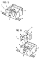
- Figure 5 shows the result achieved by the lowering of the assembly 12 within the complex constituted by the support 2 and the die 7.
- the slot 15 is located exactly in line beneath the slot 8.
- the two slots in question usually have approximately corresponding dimensions, the slot 15 preferably being slightly larger and/or having a slight flair so as to provide a "lead-in" to the punch 14 when it is lowered.
- the product K subsequently introduced (by known means) into the duct 16 falls vertically within the punch 14 so as to be deposited in the bottom loop of the semi-finished wrapper S in the notch 5 in the gear 4.
- the sheet-supply assembly (comprising the elements 11 and the strip G of sheet material from which the portion T forming the semi-finished wrapper S has been removed), as well as the inserter assembly (comprising the elements 13 and 16) are moved away from the support 2.
- the two assemblies in question are usually made in the form of vertically-movable assemblies which are able to descend to engage the support 2 and the die 7.
- the complex formed by the support 2 and the die 7 (and rack 6 which - for reasons which will become clear below - must be held in a fixed position relative to the elements 2 and 7 initially) may be movable so as to allow its disengagement from the assemblies indicated above.
- the desired result is as follows: the support 2 containing (within the cavity 3) the gear 4 with the notch 5 within which is the semi-finished wrapper S and the product K is accessible from the open side of the semi-finished wrapper once the die 7 has been removed from the support 2.
- the die 7 itself serves both as a guide element for the sheet-supply assembly and the inserter assembly and as a stabilising element for cooperating with the support 2 during the formation of the semi-finished wrapper S.
- a new supply assembly is brought close to the support 2 so that it can cooperate with the semi-finished wrapper S.
- the assembly 17 is intended to cooperate with the end portions of the semi-finished wrapper S which project laterally (at both ends in the example illustrated which shows the formation of a double-twist wrapper) from the body of the semi-finished wrapper S containing the product K and, hence, from the outer faces of the walls of the support 2 defining the cavity 3.
- the assembly 17 is composed essentially of a pair of retaining or gripping elements 18 shown here in the form of jaws. Once the assembly 17 has been lowered so as to bring the jaws 18 to the height of the projecting ends of the semi-finished wrapper S, the jaws themselves, here shown with the clamping zone oriented vertically, may be closed so as to grip the ends of the semi-finished wrapper S between them, these ends also extending vertically.
- the gripper elements here shown in the form of the jaws 18 are intended to hold the ends of the semi-finished wrapper S during the formation of the wrapper twists.
- the gripping action must at the same time be firm and not too vigorous: on the one hand it must prevent the ends of the semi-finished wrapper S escaping the gripping action but it is also true that this same gripping action must not oppose the formation of the twists by the twisting of the semi-finished wrapper S about its longitudinal axis.
- the jaws 18 must be able to allow the sheet material constituting the end portions of the semi-finished wrapper S to slide between them to a certain extent during the formation of the twisted ends.
- the degree and intensity of the gripping action must thus be determined selectively and in dependence on specific applicational requirements, taking into account firstly parameters such as the dimensions of the wrapper (and hence of the twisted ends) and the characteristics of the sheet material constituting the wrapper itself (thickness, degree of deformability, maximum breaking stress, slip, etc).
- the result is the movement of the rack 6 relative to the support 2 and the consequent rotation of the gear 4 (the outer teeth of which mesh with the rack 6) about its axis within the its housing cavity 3 in the support 2.
- the rotation imparted to the gear 4 results in a corresponding rotation of the notch 5 in which the central portion, or body, of the semi-finished wrapper S containing the product K is located while the ends of the semi-finished wrapper S are held stationary by the jaws 18 of the assembly 17 so as not to be able to rotate.
- the overall result is that the body of the semi-finished wrapper S rotates relative to the ends and consequently the two twisted end portions, or twists F shown in Figure 10 are formed.
- the solution according to the invention is thus aimed in a different direction from the prior art solutions in which the twisting of the semi-finished wrapper S required to form the twist or twists F is achieved by the rotation of the end or ends of the semi-finished wrapper relative to the body of the semi-finished wrapper.
- the or each end is held stationary (in the embodiment illustrated, by the jaws 18) while the body is rotated (in the example illustrated by the gear 4).
- the invention thus enables the equipment used for the formation of the twists to be simplified considerably in that the gripper elements 18 need not to rotate which considerably simplifies the structure.
- the part which houses the body of the semi-finished wrapper that is rotated this, in the example illustrated, being the same part in which the semi-finished wrapper has previously been formed and in which the product K has been inserted (preferably, as in the example illustrated, by being dropped) into the semi-finished wrapper itself.
- the solution of the invention enables the structure of the semi-finished wrapper to be simplified, with the use of a simple channel shape (see in particular Figures 5 and 6) without the need to close the semi-finished wrapper itself into a tube around the product K: this latter operation, in various prior art solutions, involves the use of further shaping and/or temporary retaining elements for shaping the semi-finished wrapper tube and/or holding the semi-finished wrapper closed during the formation of the twists.
- the assembly 17 is raised so as to remove it from the support 2 (again in this case, the same result could be achieved by the lowering of the support 2 and associated members relative to the assembly 17) with the jaws 18 kept closed so as to retain the wrapper P, now completely formed with the twists F, between them and to remove it from the notch 5 and hence from the support 2.
- the assembly 17 may be used for example to transfer the completed wrapper P to a further work-station (for example a machine for inserting it in a box or bag) where the completed wrappers are freed by the opening of the jaws 18 so as to release the twisted ends F.
- the situation illustrated is not a limitation in that, in most cases, it corresponds to the need to rotate the gear 4 through 360° by means of the relative movement of the rack 6 and the support 2. Even if the material of the wrapper has a certain resilience so that it tends to return to its undeformed condition after the formation of the twists, this angle of rotation suffices, without any other means, to create twists which remain firmly closed.
Landscapes
- Engineering & Computer Science (AREA)
- Mechanical Engineering (AREA)
- Making Paper Articles (AREA)
- Packages (AREA)
- Brushes (AREA)
- Wire Processing (AREA)
Abstract
Description
- The present invention relates to a method for forming twist wrappers and equipment for carrying out the method.
- Wrappers definable as twist wrappers are usually used in the food industry, and particularly in the confectionery sector, for packaging products such as boiled sweets, comfits, pastilles, etc. Essentially, in the solutions in current use, a semi-finished wrapper is first formed comprising a hollow or tubular-shaped wrapper sheet (possibly in several layers) in which the product is inserted. After the insertion of the product, the semi-finished wrapper is twisted adjacent the or each open end which results in the formation of the respective twisted projecting end portion.
- The prior art is very extensive as evidenced, for example, by the documents FR-A-1529212, GB-A-105541, GB-A-1365840, US-A-2243633, US-A-2744370, US-A-3131522, US-A-3899865, US-A-4352265, US-A-4768639, US-A-4866922, US-A-4918901 and US-A-5016421.
- With a certain degree of simplification but keeping essentially to the facts, one can say that, in prior-art solutions, each twisted end is formed with the "body" of the semi-finished wrapper (that is, the part in which the product is located) held stationary while the end portion or portions projecting therefrom are acted upon by a twisting member, typically a rotary gripper. In essence, all these known solutions duplicate, by means of a machine, the action of an operator who forms the twist manually.
- The use of this type of solution on an industrial scale runs into an obstacle when it is desired to operate at very high rates on huge quantities of the product because of the intrinsic complexity of the apparatus which in fact prevents certain speeds and production levels from being achieved.
- Reference is made here in particular to document DE-A-25 52 600.
- The object of the present invention is to provide a solution which overcomes the intrinsic difficulties linked with the use of prior-art solutions, particularly in relation to the following factors:
- complexity of the members which form the twists,
- formation of the semi-finished wrapper, and
- insertion of the product in the semi-finished wrapper and retention thereof during the formation of the twist or twists.
- According to the present invention, this object is achieved by a method having the characteristics called for in the claims which follow.
- A further subject of the invention is equipment for carrying out this method.
- The invention will now be described, purely by way of non-limitative example, with reference to the appended drawings comprising Figures 1 to 10 which illustrate schematically a typical sequence by which the method of the invention is carried out.
- By way of introduction it should be noted that the representations provided in the appended drawings are deliberately simplified and aim primarily to show the essential characteristics of the method of the invention.
- More particularly, the description which follows relates specifically to an element or module of equipment for forming a twist wrapper (in this specific case a double-twist wrapper) around one product at a time. Since the module may be reproduced on a large scale, for example in the form of a matrix structure (each including m rows of n modules of the type illustrated in the appended drawings), it is possible to form equipment which is able to act simultaneously on m by n products, where m x n is a very large number (even of the order of hundreds). It is thus possible to form equipment which is able to achieve productivity levels of the order of thousands (in some cases tens of thousands) of wrapped products every minute.
- It should also be pointed out that the structure of the equipment shown in the appended drawings is deliberately simplified by the omission of several parts having structures and functions which are well known in this branch of the art and which are not, in any case, essential for an understanding of the invention. Again it must be pointed out that the example illustrated is, indeed, just that, since the same method can be carried out by equipment very different from that illustrated by way of example.
- In the appended
drawings reference 1 generally indicates equipment usable to package products (typically sweet products such as boiled sweets and pastilles) in a twist wrapper. One is dealing specifically with a double-twist wrapper of the type generally indicated P in Figure 10. - In a known solution, the wrapper in question is made from sheet material (of paper, laminated plastics, aluminium etc), possibly with several layers. The wrapper in question is first wrapped around the pre-made product (here shown in the form of a disc-shaped pastille K) so as to form a channel-shaped, semi-finished wrapper and then it is twisted adjacent its ends to form two twisted, projecting end portions indicated F.
- The core of the
equipment 1 is constituted by asupport 2, for example of metal, having an opening orcavity 3 in which agear wheel 4 is mounted for rotation (in this embodiment about a horizontal axis), the gear having a radial slit ornotch 5. Thenotch 5 may be seen as corresponding to a sort of slot created in the body of thegear 4 so as to create a recess which extends from a central portion of thegear 4 to open into its periphery which is toothed (partially or completely). In the embodiment illustrated, the notch in question is generally straight which, although preferred, should not be understood as imperative. - The same is also true with regard to the peripheral teeth of the
gear 4 which cooperate, according to criteria which will be more fully explained below, with a rack ortoothing 6 illustrated here as generally beneath thesupport 2, thesupport 2 being able to move relative to therack 6. As will be more fully explained below, the meshing of thegear 4 with therack 6 is intended to make the translational movement of thesupport 2 along therack 6 cause thegear 4 itself to rotate about its central axis. Although the illustration shows the solution which is currently preferred in terms of reliability and simplicity, the same practical result (rotation of the gear 4) could be achieved in a different manner, for example by a drive associated with thegear 4. Needless to say, in this case, the gear need not necessarily be toothed and, in general, the gear could be replaced by any body capable of achieving the rotation of thenotch 5, it thus not being essential to make use of a gear as such. - Consequently, even though the description below will make reference to the
gear 4 and, in particular, agear 4 which cooperates with arack 6, it is understood that this choice is in no way binding. -
Reference 7 indicates (see in particular Figure 2) a sort of die intended to be superposed on thesupport 2 so as to locate aslot 8 for use in the formation of the semi-finished wrapper and in the insertion of the product K in the semi-finished wrapper over thecavity 3 in which thegear 4 is located. - From an observation of Figure 1, it will further be noted that the
support 2 also has a further notch 9 in a position generally aligned with theslot 8 when thedie 7 is applied to thesupport 2, this further notch being coextensive with thenotch 5 in thegear 4 in the position of formation of the semi-finished wrapper and introduction of the product (in practice in the position illustrated in Figure 1). A similar notch, indicated 10 and only partly visible in Figure 1, is provided in the other wall of thesupport 2 which defines thecavity 3 and is also aligned with thenotch 5 and the notch 9. - Figure 3 illustrates an assembly for supplying sheet material G, for forming the twist wrapper which it is desired to make, located above the
die 7 and, specifically, above the slot 8 (shown in broken outline in Figure 3). - In the embodiment illustrated, the assembly in question includes winding and unwinding reels (not illustrated, the structure being widely known in general) which carry the strip of sheet material G so that it passes over two drive rollers or
rods 11. In use, the rods orrollers 11 are brought close to the upper, flat face of the die 7 in correspondence with theslot 8. Thus a given quantity of sheet material, possibly perforated to define a piece T intended to form the wrapper for a respective product, faces the top of theslot 8. -
Reference 12 indicates a punch assembly comprising: - a
guide element 13 intended to be lowered (by drive means known per sé and not illustrated) over the piece of sheet material G located over theslot 8, and - a
punch 14 proper which can enter theslot 8 through arespective slot 15 formed in theguide element 13. The whole is as illustrated in greater detail in Figure 4. - From an observation of Figures 3 and 4, it will also be noted that the
punch 14 is in turn traversed vertically (in the embodiment illustrated) by afurther slot 16 constituting a channel or duct for the insertion of the product K to be packaged in the semi-finished wrapper formed in thesupport 2 and, more precisely, in the combination ofnotches - In particular, Figure 5 shows the result achieved by the lowering of the
assembly 12 within the complex constituted by thesupport 2 and the die 7. - More particularly, when the
element 13 is lowered over the sheet material G facing theslot 8, theslot 15 is located exactly in line beneath theslot 8. The two slots in question usually have approximately corresponding dimensions, theslot 15 preferably being slightly larger and/or having a slight flair so as to provide a "lead-in" to thepunch 14 when it is lowered. - As it is lowered through the
slots punch 14 enters thenotches - The product K subsequently introduced (by known means) into the
duct 16 falls vertically within thepunch 14 so as to be deposited in the bottom loop of the semi-finished wrapper S in thenotch 5 in thegear 4. - At this point, the sheet-supply assembly (comprising the
elements 11 and the strip G of sheet material from which the portion T forming the semi-finished wrapper S has been removed), as well as the inserter assembly (comprising theelements 13 and 16) are moved away from thesupport 2. - Clearly this movement may be of relative type. In the currently preferred solution, the two assemblies in question are usually made in the form of vertically-movable assemblies which are able to descend to engage the
support 2 and the die 7. Naturally, in a wholly equivalent solution, the complex formed by thesupport 2 and the die 7 (andrack 6 which - for reasons which will become clear below - must be held in a fixed position relative to theelements - In each case, the desired result is as follows: the
support 2 containing (within the cavity 3) thegear 4 with thenotch 5 within which is the semi-finished wrapper S and the product K is accessible from the open side of the semi-finished wrapper once thedie 7 has been removed from thesupport 2. - As will readily be understood, in the embodiment illustrated, the
die 7 itself serves both as a guide element for the sheet-supply assembly and the inserter assembly and as a stabilising element for cooperating with thesupport 2 during the formation of the semi-finished wrapper S. - Once the condition shown schematically in Figure 5 has been reached, a new supply assembly, generally indicated 17, is brought close to the
support 2 so that it can cooperate with the semi-finished wrapper S. Specifically theassembly 17 is intended to cooperate with the end portions of the semi-finished wrapper S which project laterally (at both ends in the example illustrated which shows the formation of a double-twist wrapper) from the body of the semi-finished wrapper S containing the product K and, hence, from the outer faces of the walls of thesupport 2 defining thecavity 3. - The
assembly 17 is composed essentially of a pair of retaining or grippingelements 18 shown here in the form of jaws. Once theassembly 17 has been lowered so as to bring thejaws 18 to the height of the projecting ends of the semi-finished wrapper S, the jaws themselves, here shown with the clamping zone oriented vertically, may be closed so as to grip the ends of the semi-finished wrapper S between them, these ends also extending vertically. - The gripper elements here shown in the form of the
jaws 18 are intended to hold the ends of the semi-finished wrapper S during the formation of the wrapper twists. - From this it results that the gripping action must at the same time be firm and not too vigorous: on the one hand it must prevent the ends of the semi-finished wrapper S escaping the gripping action but it is also true that this same gripping action must not oppose the formation of the twists by the twisting of the semi-finished wrapper S about its longitudinal axis. In other words, the
jaws 18 must be able to allow the sheet material constituting the end portions of the semi-finished wrapper S to slide between them to a certain extent during the formation of the twisted ends. The degree and intensity of the gripping action must thus be determined selectively and in dependence on specific applicational requirements, taking into account firstly parameters such as the dimensions of the wrapper (and hence of the twisted ends) and the characteristics of the sheet material constituting the wrapper itself (thickness, degree of deformability, maximum breaking stress, slip, etc). - Once the position illustrated in Figure 7 has been reached, with the
jaws 18 gripping the ends of the semi-finished wrapper S between them, the complex constituted by thesupport 2 and theassembly 17 is moved transationally relative to therack 6. - Usually this result is obtained with the
support 2 and theassembly 17 held stationary, in a fixed relative position, and therack 6 being slid longitudinally. It is, however, also possible to do this in the complementary manner, therack 6 being kept stationary while thesupport 2 and associatedassembly 17 are moved, or, again, with both therack 6 and thesupport 2 and theassembly 17 being moved. - Whatever solution is adopted, the result is the movement of the
rack 6 relative to thesupport 2 and the consequent rotation of the gear 4 (the outer teeth of which mesh with the rack 6) about its axis within the itshousing cavity 3 in thesupport 2. The rotation imparted to thegear 4 results in a corresponding rotation of thenotch 5 in which the central portion, or body, of the semi-finished wrapper S containing the product K is located while the ends of the semi-finished wrapper S are held stationary by thejaws 18 of theassembly 17 so as not to be able to rotate. The overall result is that the body of the semi-finished wrapper S rotates relative to the ends and consequently the two twisted end portions, or twists F shown in Figure 10 are formed. - The solution according to the invention is thus aimed in a different direction from the prior art solutions in which the twisting of the semi-finished wrapper S required to form the twist or twists F is achieved by the rotation of the end or ends of the semi-finished wrapper relative to the body of the semi-finished wrapper. On the contrary, in the solution of the invention, the or each end is held stationary (in the embodiment illustrated, by the jaws 18) while the body is rotated (in the example illustrated by the gear 4).
- The invention thus enables the equipment used for the formation of the twists to be simplified considerably in that the
gripper elements 18 need not to rotate which considerably simplifies the structure. On the contrary, it is the part which houses the body of the semi-finished wrapper that is rotated, this, in the example illustrated, being the same part in which the semi-finished wrapper has previously been formed and in which the product K has been inserted (preferably, as in the example illustrated, by being dropped) into the semi-finished wrapper itself. - These aspects also constitute a further simplification over the previously known solutions with regard to the formation of the semi-finished wrapper, the retention of the product within the semi-finished wrapper and the retention of the semi-finished wrapper, with the product within it, during the formation of the twist.
- Above all, the solution of the invention enables the structure of the semi-finished wrapper to be simplified, with the use of a simple channel shape (see in particular Figures 5 and 6) without the need to close the semi-finished wrapper itself into a tube around the product K: this latter operation, in various prior art solutions, involves the use of further shaping and/or temporary retaining elements for shaping the semi-finished wrapper tube and/or holding the semi-finished wrapper closed during the formation of the twists.
- Starting from the position illustrated in Figure 8, the
assembly 17 is raised so as to remove it from the support 2 (again in this case, the same result could be achieved by the lowering of thesupport 2 and associated members relative to the assembly 17) with thejaws 18 kept closed so as to retain the wrapper P, now completely formed with the twists F, between them and to remove it from thenotch 5 and hence from thesupport 2. At this point, theassembly 17 may be used for example to transfer the completed wrapper P to a further work-station (for example a machine for inserting it in a box or bag) where the completed wrappers are freed by the opening of thejaws 18 so as to release the twisted ends F. - Naturally the pick-up action shown in Figure 9 is here made possible by the fact that the
notch 5 is again aligned (vertically in the embodiment illustrated) with thenotches 9 and 10. Naturally this does not exclude the possibility of the completed wrapper being withdrawn to some extent even in the absence of such alignment. - In any case, the situation illustrated is not a limitation in that, in most cases, it corresponds to the need to rotate the
gear 4 through 360° by means of the relative movement of therack 6 and thesupport 2. Even if the material of the wrapper has a certain resilience so that it tends to return to its undeformed condition after the formation of the twists, this angle of rotation suffices, without any other means, to create twists which remain firmly closed.
Claims (12)
- A method for forming twist wrappers, including the steps of:characterized in that it includes the steps of:forming a semi-finished wrapper (S) of sheet material (G) including a body portion which houses a pre-made product (K) in the wrapper and at least one end portion which projects from the body portion, the body portion being housed in a rotary body (4) having a notch-like recess (5) for the formation of the semi-finished wrapper (S), andproducing relative twisting of the at least one end portion and the body portion so as to form at least one twist, the twisting being effected with the at least one end portion held stationary and the body portion being rotated,providing a support(2) having a cavity (3) in which the rotary body (4) is housed, the said rotary body (4) being rotatable about an axis of said support (2) and the said support (2) having at least one notch (9, 10) communicating with said cavity (3),aligning the notch-like recess (5) of the rotary body (4) with the at least one notch (9, 10) of the support (2), andintroducing the sheet material (G) into the notch-like recess (5) so as to form the semi-finished wrapper (S) with a generally channel shape and at least one end portion projecting from the notch-like recess (5).
- A method according to Claim 1, characterized in that the body portion is rotated through an angle of substantially 360°
- A method according to Claim 1 or Claim 2, characterized in that it includes the steps of:gripping (18) the at least one end portion of the semi-finished wrapper (S), andimparting a generally rotational movement to the body (4) and hence the notch-like recess (5) while holding the at least one gripped end portion of the semi-finished wrapper (S) substantially stationary.
- Equipment for forming twist wrappers, comprising:characterized in that the rotary body (4) is housed in a cavity (3) of a support (2), the said rotary body (4) being rotatable about an axis of said support (2) and the said support (2) having at least one notch (9, 10) which communicates with the cavity (3) and with which the notch-like recess (5) in the rotary body can be aligned in use to receive the sheet material (G) from the inserter means (12 to 16).a rotary body (4) which has a notch-like recess (5) extending radially,supply means (11) for supplying sheet material (G) for forming the wrapper,inserter means (12 to 16) for inserting the sheet material (G) into the notch-like recess (5) so as to form a semi-finished wrapper (S) having a generally channel shape with a body portion housed in the notch-like recess (5) and at least one end portion projecting from the notch-like recress (5),supply means (16) for inserting a product (K) to be wrapped in the body portion of the semi-finished wrapper (S),retaining means (18) for engaging the at least one end portion of the semi-finished wrapper (S) so as to retain it against rotational movement, anddrive means (6) for selectively rotating the rotary body (4), and hence the notch (5), about the axis, with the consequent rotation of the body portion of the semi-finished wrapper (S) relative to the at least one end portion engaged by the retaining means (18) and the formation of a twist in the at least one end portion,
- Equipment according to Claim 4, characterized in that the rotary body is constituted by a gear wheel (4) and the drive means comprise gear teeth (6) meshed with the teeth of the gear wheel.
- Equipment according to Claim 5, characterized in that the notch-like recess is constituted by a radial notch (5) formed in the gear wheel (4).
- Equipment according to any one of Claims 4 to 6, characterized in that it includes a die element (7) including a slot (8) with which the notch-like recess (5) can be aligned selectively and in that the inserter means (12 to 16) insert the sheet material (G) in the notch-like recess (5) through the slot (8).
- Equipment according to any one of Claims 4 to 7, characterized in that the inserter means comprise a punch element (14) which can enter the notch-like recess (5) so as to thrust the sheet material (G) into the notch (5).
- Equipment according to Claim 8, characterized in that the punch element (14) has a longitudinal hole (16) defining a duct for the introduction of the product (K) into the body portion of the semi-finished wrapper (S).
- Equipment according to Claim 8 or Claim 9, characterized in that the punch element (14) carries an associated guide element (13) with a respective slot (15) forming an insertion- and guide- aperture for the punch element (14).
- Equipment according to any one of Claims 4 to 10, characterized in that the retaining means comprise at least one gripper formation (18) which is movable relative to the rotary body (4) so as to grip at the least one end portion of the semi-finished wrapper (S).
- Equipment according to Claim 11, characterized in that the retaining means comprise a pair of jaws (18) which are movable relative to the rotary body (4) so as to be locatable on opposite sides of the rotary body (4) itself so as to grip respective end portions of the semi-finished wrapper (S) projecting from opposite sides of the rotary body (4).
Applications Claiming Priority (3)
| Application Number | Priority Date | Filing Date | Title |
|---|---|---|---|
| CH95196 | 1996-04-15 | ||
| CH951/96 | 1996-04-15 | ||
| CH00951/96A CH691372A5 (en) | 1996-04-15 | 1996-04-15 | A process for forming wrappings in a bow and relative device. |
Publications (2)
| Publication Number | Publication Date |
|---|---|
| EP0802116A1 EP0802116A1 (en) | 1997-10-22 |
| EP0802116B1 true EP0802116B1 (en) | 2004-06-23 |
Family
ID=4198973
Family Applications (1)
| Application Number | Title | Priority Date | Filing Date |
|---|---|---|---|
| EP97105913A Expired - Lifetime EP0802116B1 (en) | 1996-04-15 | 1997-04-10 | A method for forming twist wrappers and the respective equipment |
Country Status (5)
| Country | Link |
|---|---|
| EP (1) | EP0802116B1 (en) |
| AT (1) | ATE269809T1 (en) |
| CH (1) | CH691372A5 (en) |
| DE (1) | DE69729601T2 (en) |
| ES (1) | ES2218614T3 (en) |
Families Citing this family (1)
| Publication number | Priority date | Publication date | Assignee | Title |
|---|---|---|---|---|
| ITTO20060295A1 (en) | 2006-04-20 | 2007-10-21 | Soremartec Sa | DEVICE FOR REALIZING FOOD ITEMS RELATIVE TO PROCEDURE AND PLANT |
Family Cites Families (4)
| Publication number | Priority date | Publication date | Assignee | Title |
|---|---|---|---|---|
| US2346613A (en) * | 1941-03-14 | 1944-04-11 | Jr Herbert Rumsey | Wrapping machine |
| US2598073A (en) * | 1950-01-25 | 1952-05-27 | Jr Herbert Rumsey | Wrapping and twisting apparatus |
| DE2552600A1 (en) * | 1975-11-24 | 1977-06-02 | Ernst Kurt Poepel | Sweet rotary wrapping system - two endless belts clamping wrapping end in between them |
| GB2043021A (en) * | 1979-03-02 | 1980-10-01 | Tex Del Inc | Method of and apparatus for wrapping cylindrical articles |
-
1996
- 1996-04-15 CH CH00951/96A patent/CH691372A5/en not_active IP Right Cessation
-
1997
- 1997-04-10 DE DE69729601T patent/DE69729601T2/en not_active Expired - Lifetime
- 1997-04-10 EP EP97105913A patent/EP0802116B1/en not_active Expired - Lifetime
- 1997-04-10 ES ES97105913T patent/ES2218614T3/en not_active Expired - Lifetime
- 1997-04-10 AT AT97105913T patent/ATE269809T1/en not_active IP Right Cessation
Also Published As
| Publication number | Publication date |
|---|---|
| EP0802116A1 (en) | 1997-10-22 |
| DE69729601T2 (en) | 2005-06-30 |
| CH691372A5 (en) | 2001-07-13 |
| ES2218614T3 (en) | 2004-11-16 |
| ATE269809T1 (en) | 2004-07-15 |
| DE69729601D1 (en) | 2004-07-29 |
Similar Documents
| Publication | Publication Date | Title |
|---|---|---|
| DE3872476T2 (en) | METHOD AND DEVICE FOR REMOVING YARN SPOOLS AND PUTTING THESE REELS INTO A REEL WAGON. | |
| EP0226872B1 (en) | Device for making (cigarette) packages from at least one foldable blank | |
| DE2526047A1 (en) | REVOLVING CONVEYOR ON A WRAPPING MACHINE | |
| EP1515403B1 (en) | Cable processing apparatus | |
| US2954599A (en) | Lead making apparatus | |
| DE2809360C3 (en) | Method and device for winding and cassette film tape | |
| GB2330545A (en) | Preparing lengths of wire in a harness making machine | |
| CH616125A5 (en) | ||
| EP1712472A1 (en) | Method and device for packaging small products | |
| DE4314142C1 (en) | Device for folding a packaging envelope for folding bags or cups | |
| EP0802116A1 (en) | A method for forming twist wrappers and the respective equipment | |
| US4263708A (en) | Machine for automatically inserting parallel lead electronic components into a printed circuit board | |
| DE1280129B (en) | Machine for the automatic production of evacuated soft packs | |
| EP1988044B1 (en) | Coiler and method for manufacturing a coil | |
| DE3621651C2 (en) | Device for the production of filter bags for infusion products and for the individual packaging of the filter bags in an outer casing | |
| EP2919615A1 (en) | Tuft forming apparatus | |
| DE2329534C3 (en) | Device for the continuous wrapping of sweets or similar small parts | |
| US5839259A (en) | Method for assembling dental floss dispenser products | |
| DE1774759B2 (en) | Length measuring and storage device on bundle winding machines for wire-shaped flexible goods | |
| US4217979A (en) | Production of blocks of rod-shaped articles | |
| EP0915017A1 (en) | Process and device for packaging small articles, in particular candy products | |
| KR102049209B1 (en) | Device for automatic insertion of heat-shrinkable film into packaging containers | |
| EP0236213B1 (en) | Automatic process for making coils without supporting frame and for mounting them on a printed circuit, and machine for carrying out the process | |
| US20220348390A1 (en) | Grouped screw bunch and related method and machine for production of the same | |
| AT277873B (en) | Machine for the automatic production of evacuated packs from thin plastic films |
Legal Events
| Date | Code | Title | Description |
|---|---|---|---|
| PUAI | Public reference made under article 153(3) epc to a published international application that has entered the european phase |
Free format text: ORIGINAL CODE: 0009012 |
|
| AK | Designated contracting states |
Kind code of ref document: A1 Designated state(s): AT BE CH DE DK ES FI FR GB GR IE IT LI LU MC NL PT SE |
|
| AX | Request for extension of the european patent |
Free format text: AL PAYMENT 970410;LT PAYMENT 970410;LV PAYMENT 970410;RO PAYMENT 970410;SI PAYMENT 970410 |
|
| 17P | Request for examination filed |
Effective date: 19980416 |
|
| 17Q | First examination report despatched |
Effective date: 20020611 |
|
| GRAP | Despatch of communication of intention to grant a patent |
Free format text: ORIGINAL CODE: EPIDOSNIGR1 |
|
| GRAS | Grant fee paid |
Free format text: ORIGINAL CODE: EPIDOSNIGR3 |
|
| GRAA | (expected) grant |
Free format text: ORIGINAL CODE: 0009210 |
|
| RAP1 | Party data changed (applicant data changed or rights of an application transferred) |
Owner name: FERRERO OFFENE HANDELSGESELLSCHAFT M.B.H. Owner name: FERRERO S.P.A. Owner name: SOREMARTEC S.A. |
|
| AK | Designated contracting states |
Kind code of ref document: B1 Designated state(s): AT BE CH DE DK ES FI FR GB GR IE IT LI LU MC NL PT SE |
|
| AX | Request for extension of the european patent |
Extension state: AL LT LV RO SI |
|
| PG25 | Lapsed in a contracting state [announced via postgrant information from national office to epo] |
Ref country code: NL Free format text: LAPSE BECAUSE OF FAILURE TO SUBMIT A TRANSLATION OF THE DESCRIPTION OR TO PAY THE FEE WITHIN THE PRESCRIBED TIME-LIMIT Effective date: 20040623 Ref country code: LI Free format text: LAPSE BECAUSE OF FAILURE TO SUBMIT A TRANSLATION OF THE DESCRIPTION OR TO PAY THE FEE WITHIN THE PRESCRIBED TIME-LIMIT Effective date: 20040623 Ref country code: FI Free format text: LAPSE BECAUSE OF FAILURE TO SUBMIT A TRANSLATION OF THE DESCRIPTION OR TO PAY THE FEE WITHIN THE PRESCRIBED TIME-LIMIT Effective date: 20040623 Ref country code: CH Free format text: LAPSE BECAUSE OF FAILURE TO SUBMIT A TRANSLATION OF THE DESCRIPTION OR TO PAY THE FEE WITHIN THE PRESCRIBED TIME-LIMIT Effective date: 20040623 Ref country code: AT Free format text: LAPSE BECAUSE OF FAILURE TO SUBMIT A TRANSLATION OF THE DESCRIPTION OR TO PAY THE FEE WITHIN THE PRESCRIBED TIME-LIMIT Effective date: 20040623 |
|
| REG | Reference to a national code |
Ref country code: GB Ref legal event code: FG4D |
|
| REG | Reference to a national code |
Ref country code: CH Ref legal event code: EP |
|
| REG | Reference to a national code |
Ref country code: IE Ref legal event code: FG4D |
|
| REF | Corresponds to: |
Ref document number: 69729601 Country of ref document: DE Date of ref document: 20040729 Kind code of ref document: P |
|
| PG25 | Lapsed in a contracting state [announced via postgrant information from national office to epo] |
Ref country code: DK Free format text: LAPSE BECAUSE OF FAILURE TO SUBMIT A TRANSLATION OF THE DESCRIPTION OR TO PAY THE FEE WITHIN THE PRESCRIBED TIME-LIMIT Effective date: 20040923 |
|
| REG | Reference to a national code |
Ref country code: GR Ref legal event code: EP Ref document number: 20040402706 Country of ref document: GR |
|
| REG | Reference to a national code |
Ref country code: SE Ref legal event code: TRGR |
|
| REG | Reference to a national code |
Ref country code: ES Ref legal event code: FG2A Ref document number: 2218614 Country of ref document: ES Kind code of ref document: T3 |
|
| LTIE | Lt: invalidation of european patent or patent extension |
Effective date: 20040623 |
|
| NLV1 | Nl: lapsed or annulled due to failure to fulfill the requirements of art. 29p and 29m of the patents act | ||
| REG | Reference to a national code |
Ref country code: CH Ref legal event code: PL |
|
| ET | Fr: translation filed | ||
| PG25 | Lapsed in a contracting state [announced via postgrant information from national office to epo] |
Ref country code: LU Free format text: LAPSE BECAUSE OF NON-PAYMENT OF DUE FEES Effective date: 20050410 |
|
| PLBE | No opposition filed within time limit |
Free format text: ORIGINAL CODE: 0009261 |
|
| STAA | Information on the status of an ep patent application or granted ep patent |
Free format text: STATUS: NO OPPOSITION FILED WITHIN TIME LIMIT |
|
| PG25 | Lapsed in a contracting state [announced via postgrant information from national office to epo] |
Ref country code: MC Free format text: LAPSE BECAUSE OF NON-PAYMENT OF DUE FEES Effective date: 20050430 |
|
| 26N | No opposition filed |
Effective date: 20050324 |
|
| PG25 | Lapsed in a contracting state [announced via postgrant information from national office to epo] |
Ref country code: PT Free format text: LAPSE BECAUSE OF NON-PAYMENT OF DUE FEES Effective date: 20041123 |
|
| REG | Reference to a national code |
Ref country code: GB Ref legal event code: 732E Free format text: REGISTERED BETWEEN 20140313 AND 20140319 |
|
| REG | Reference to a national code |
Ref country code: FR Ref legal event code: TP Owner name: SOREMARTEC S.A., LU Effective date: 20140402 |
|
| REG | Reference to a national code |
Ref country code: ES Ref legal event code: PC2A Owner name: SOREMARTEC, S.A. Effective date: 20140703 Ref country code: ES Ref legal event code: PC2A Owner name: SOREMARTEC, S.A. Effective date: 20140613 |
|
| BECA | Be: change of holder's address |
Owner name: S.A. *SOREMARTECFINDEL BUSINESS CENTER, COMPLEXE B Effective date: 20140717 |
|
| PGFP | Annual fee paid to national office [announced via postgrant information from national office to epo] |
Ref country code: IE Payment date: 20140428 Year of fee payment: 18 Ref country code: GB Payment date: 20140422 Year of fee payment: 18 |
|
| PGFP | Annual fee paid to national office [announced via postgrant information from national office to epo] |
Ref country code: FR Payment date: 20140430 Year of fee payment: 18 Ref country code: IT Payment date: 20140417 Year of fee payment: 18 Ref country code: SE Payment date: 20140422 Year of fee payment: 18 Ref country code: DE Payment date: 20140414 Year of fee payment: 18 Ref country code: ES Payment date: 20140424 Year of fee payment: 18 Ref country code: GR Payment date: 20140423 Year of fee payment: 18 |
|
| PGFP | Annual fee paid to national office [announced via postgrant information from national office to epo] |
Ref country code: BE Payment date: 20140418 Year of fee payment: 18 |
|
| REG | Reference to a national code |
Ref country code: DE Ref legal event code: R119 Ref document number: 69729601 Country of ref document: DE |
|
| REG | Reference to a national code |
Ref country code: SE Ref legal event code: EUG |
|
| GBPC | Gb: european patent ceased through non-payment of renewal fee |
Effective date: 20150410 |
|
| REG | Reference to a national code |
Ref country code: IE Ref legal event code: MM4A |
|
| PG25 | Lapsed in a contracting state [announced via postgrant information from national office to epo] |
Ref country code: GB Free format text: LAPSE BECAUSE OF NON-PAYMENT OF DUE FEES Effective date: 20150410 Ref country code: GR Free format text: LAPSE BECAUSE OF NON-PAYMENT OF DUE FEES Effective date: 20151106 Ref country code: IT Free format text: LAPSE BECAUSE OF NON-PAYMENT OF DUE FEES Effective date: 20150410 Ref country code: DE Free format text: LAPSE BECAUSE OF NON-PAYMENT OF DUE FEES Effective date: 20151103 |
|
| REG | Reference to a national code |
Ref country code: FR Ref legal event code: ST Effective date: 20151231 |
|
| REG | Reference to a national code |
Ref country code: GR Ref legal event code: ML Ref document number: 20040402706 Country of ref document: GR Effective date: 20151106 |
|
| PG25 | Lapsed in a contracting state [announced via postgrant information from national office to epo] |
Ref country code: SE Free format text: LAPSE BECAUSE OF NON-PAYMENT OF DUE FEES Effective date: 20150411 Ref country code: FR Free format text: LAPSE BECAUSE OF NON-PAYMENT OF DUE FEES Effective date: 20150430 |
|
| PG25 | Lapsed in a contracting state [announced via postgrant information from national office to epo] |
Ref country code: IE Free format text: LAPSE BECAUSE OF NON-PAYMENT OF DUE FEES Effective date: 20150410 |
|
| REG | Reference to a national code |
Ref country code: ES Ref legal event code: FD2A Effective date: 20160527 |
|
| PG25 | Lapsed in a contracting state [announced via postgrant information from national office to epo] |
Ref country code: ES Free format text: LAPSE BECAUSE OF NON-PAYMENT OF DUE FEES Effective date: 20150411 |
|
| PG25 | Lapsed in a contracting state [announced via postgrant information from national office to epo] |
Ref country code: BE Free format text: LAPSE BECAUSE OF NON-PAYMENT OF DUE FEES Effective date: 20150430 |