EP0802104B2 - Steering column for motor vehicles - Google Patents
Steering column for motor vehicles Download PDFInfo
- Publication number
- EP0802104B2 EP0802104B2 EP97105348A EP97105348A EP0802104B2 EP 0802104 B2 EP0802104 B2 EP 0802104B2 EP 97105348 A EP97105348 A EP 97105348A EP 97105348 A EP97105348 A EP 97105348A EP 0802104 B2 EP0802104 B2 EP 0802104B2
- Authority
- EP
- European Patent Office
- Prior art keywords
- plates
- steering
- mounting part
- arms
- type projections
- Prior art date
- Legal status (The legal status is an assumption and is not a legal conclusion. Google has not performed a legal analysis and makes no representation as to the accuracy of the status listed.)
- Expired - Lifetime
Links
Images

Classifications
-
- B—PERFORMING OPERATIONS; TRANSPORTING
- B62—LAND VEHICLES FOR TRAVELLING OTHERWISE THAN ON RAILS
- B62D—MOTOR VEHICLES; TRAILERS
- B62D1/00—Steering controls, i.e. means for initiating a change of direction of the vehicle
- B62D1/02—Steering controls, i.e. means for initiating a change of direction of the vehicle vehicle-mounted
- B62D1/16—Steering columns
- B62D1/18—Steering columns yieldable or adjustable, e.g. tiltable
- B62D1/184—Mechanisms for locking columns at selected positions
Definitions
- the invention relates to a steering column for motor vehicles with a fixable to a body part mounting part, between the legs of a steering shaft receiving tubular casing is located according to the features of the preamble of claim 1
- the invention aims to form a convenient and easy to install steering column so that it is adjustable in both the longitudinal and transverse direction in a wide range.
- the invention is for solving this problem by the features of the characterizing part of claim 1.
- Advantageous embodiments of the invention are set forth in the dependent claims.
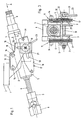
- the steering column according to FIGS. 1 to 3 has a U-shaped mounting part 1 (console), which is fixed with its flat top to a body part of a motor vehicle, not shown here, and suitably so that in the event of a crash in the plane ( Fig. 1) is displaceable. Since this storage is not the subject of the invention, it will not be discussed further in the following.
- the vertical leg 3 of this U-shaped mounting part 1 (console) are directed downward, these legs 3 are formed so that the mounting part 1 both in plan view (viewing perpendicular to the top 2 - Fig. 2) as well as in view (Fig 3) shows a U-shape.
- the extension of the legs 3 is parallel to the upper side 2 of the mounting member 1 is greater than the extension at right angles thereto.
- a jacket tube 4 with plane parallel side edges 5 (Fig. 3).
- the steering shaft 6 is accommodated, which is formed in a telescopic manner and which consists of a tubular tube 4 fixed in the tubular part and an opposite this tubular part axially displaceable shaft 7.
- This shaft 7 is connected at its end via an unspecified universal joint 8 with the steering gear.
- the other end 9 of the steering shaft 6 carries the steering wheel, not shown.
- a second plate pack 17 of substantially rectangular blades 18 is fixed at its two ends 19 on the side edge 5 of the jacket tube. These ends 19 of the rectangular blades ( Figure 6) are supported by bolts 29 fixed to the casing. Appropriately, these lamellae are threaded onto the bolt 29 only, without being directly connected to them. These rectangular lamellae 18 likewise have a slot 20 and these lamellae 18 sandwich the first-mentioned lamella packet 11, wherein the elongated slot recesses 16 and 20 of the two lamellae packets 11 and 17 intersect and thus delimit a passage opening through which the clamping bolt 10 protrudes.
- the clamping bolt 10 is dimensioned so long that it projects beyond these two packages on both sides.
- a pressure plate 21 is fixed, which rests against the outside of the outermost lamella of a disk set.
- a clamping member 22 is arranged with an actuating lever 23.
- This clamping member 22 consists for example of two interspersed by the clamping bolt 10 discs 30, 31, of which the one with respect to the other with the actuating lever 23 is rotatable, for example over an angular range of 40 ° to 45 °.
- the pressure plate 21 has on its side facing the disk pack a central guide bar 24 which cooperates with the edges of the oblong hole 16 of the outer plate 12 of a disk set 11 and which serves to secure the position or rotation of this pressure plate 21.
- this pressure plate 21 has knob-like elevations 25, which define discrete pressure points in cooperation with the slats.
- Corresponding to these nub-like elevations 25 on the pressure plate 21 can be integrally formed on the slats 12 and 18 parallel to the respective slot recesses 26, so that when tightened tendon 22, the fins 12 and 18 of the two disk sets 11 and 17 on structurally defined, discrete pressure points abut each other.
- the clamping member 22 is tightened and locked due to its structural design described above in its position.
- the clamping bolt 10 thereby presses the fins of the two disk sets 11 and 17 firmly together in the manner of a closed-plate clutch, whereby the set position of the steering column is secured. If the steering wheel to be adjusted, the driver of the motor vehicle actuates the actuating lever 23 to release the tendon 22. As a result, the "multi-plate clutch" is opened, and the jacket tube 4 can now be compared to the fixed mounting part 1 in its longitudinal direction (arrow 27) to be displaced, to an extent corresponding to the length of the slot recess 20 in the disk set 17.
- the invention is not limited to the number of slats of the disk packs shown. Eventually, the arrangement of a disk set on one side of the mounting part 1 is sufficient.
- bolts 4 are fixed to the jacket tube on which these slats are threaded.
- the recorded by the bolt 29 ends can be designed so that they lie directly against each other, because these lamellae 18 have due to their length a sufficiently large free spring travel, the tension with the Slats 12 the other disk set 11 allows. But it is also possible to insert 18 rubbery washers or sleeves between the ends of these fins.
- the clamping bolt 10 may be formed as an expansion screw or clamped with a prestressed spring assembly to prevent a change in the clamping force due to thermal expansion and associated changes in length as much as possible.
- the steering wheel can be adjusted in both the height and the steering column in its length. This is u.a. achieved in that both disk sets 11, 17 have slot recesses which intersect. If one of the disk packs has only LanglochausEnglishept and the other disk set only a simple insertion opening for the clamping bolt, then either only the steering column in length or only the steering wheel can be adjusted in height.
- pressure plates 21 are expediently provided on the outsides of both disc packs.
- lamellae packets are arranged on both sides of the leg 3 of the mounting part 1, each consisting of several individual lamellae.
- the number of slats depends on the particular application. It is conceivable that each disk set only consists of one blade, so that two intersecting blades are provided on both sides of the mounting member.
Description
Die Erfindung bezieht sich auf eine Lenksäule für Kraftfahrzeuge mit einem an einem Karosserieteil festlegbaren Montageteil, zwischen dessen Schenkeln ein die Lenkspindel aufnehmendes Mantelrohr liegt nach den Merkmalen des Oberbegriffes des Patentanspruches 1The invention relates to a steering column for motor vehicles with a fixable to a body part mounting part, between the legs of a steering shaft receiving tubular casing is located according to the features of the preamble of
Im modernen Kraftfahrzeugbau sind die Lenksäulen so ausgebildet und gelagert, daß das endseitig an der Lenksäule festgelegte Lenkrad verstellbar ist, entweder in der Höhe oder in der Entfernung zum Lenker oder auch beide Einstellungsmöglichkeiten aufweist. Dies setzt eine verschiebbare oder verschwenkbare Lagerung der die Lenksäule bildenden Teile voraus, wobei darüberhinaus Klemm- und Spannglieder vorgesehen werden müssen, die diese Verschiebbarkeit sichern, zuverlässig und auf Dauer blockieren, andererseits aber diese Spann- und Klemmglieder leicht betätigbar sein müssen, um im Bedarfsfall das Lenkrad in die gewünschte Stellung zu bringen und in dieser Stellung dann auch verläßlich festzuhalten. Beispiele dafür zeigen und beschreiben die DE-A-44 00 306, DE-A-40 16 163 A1 sowie die EP-A-0 600 700.In modern motor vehicle steering columns are designed and stored so that the end of the steering column fixed steering wheel is adjustable, either in height or in the distance to the handlebar or both adjustment options. This requires a displaceable or pivotable mounting of the steering column forming parts, moreover clamping and tendons must be provided to secure this displacement, reliably and permanently block, on the other hand, these clamping and clamping members must be easy to operate, if necessary to bring the steering wheel in the desired position and then reliably hold in this position. Examples of this are shown and described in DE-A-44 00 306, DE-A-40 16 163 A1 and EP-A-0 600 700.
Auch die Konstruktion nach der EP-A-0 671 308 ist zu erwähnen: Zwischen den beiden Schenkeln eines Montageteiles liegt ein Gehäuse der Lenksäule, das Gabelform aufweist. An den Gabelenden sind Langlochaussparungen, die von einem Bolzen durchsetzt sind, der mit seinen beiden Enden an den Schenkeln des Montageteiles festgelegt ist. Auf der Innenseite der Gabel sind Federscheiben beidseitig angeordnet, die vom erwähnten Bolzen durchsetzt sind. Ferner sind zwischen diesen Federscheiben der beiden Seiten auf dem Bolzen frei axial beweglich zylinderförmige Druckglieder, zwischen welchen ein um die Achse des Bolzens verdrehbares Spannglied gelagert ist, mit welchen die zylinderförmigen Druckglieder nach außen gegen die Federscheiben drückbar sind. Diese Konstruktion erscheint nicht zweckmäßig, da sie mit aufwendiger Montagearbeit verbunden ist, bedingt durch die Lage der für das Verspannen erforderlichen Teile zwischen den Gabelenden des Gehäuses der Lenksäule.The construction according to EP-A-0 671 308 should also be mentioned: between the two legs of a mounting part is a housing of the steering column, which has a fork shape. At the fork ends are slot openings, which are penetrated by a bolt which is fixed with its two ends to the legs of the mounting part. On the inside of the fork spring washers are arranged on both sides, which are penetrated by the aforementioned bolt. Further, between these spring washers of the two sides on the bolt free axially movable cylindrical pressure members, between which a rotatable about the axis of the bolt clamping member is mounted, with which the cylindrical pressure members are pressed outwards against the spring discs. This construction does not appear appropriate, since it is associated with complex assembly work, due to the position of the parts required for bracing between the fork ends of the housing of the steering column.
Vor allem ist hier aber die Konstruktion nach der GB-A-2 092 966 zu erwähnen die eine gattungsgemäße Lenksäule, mit den Merkmalen des Oberbegriffs des Anspruchs 1 zeigt und beschreibt.Above all, however, the construction according to GB-A-2 092 966 to mention a generic steering column, with the features of the preamble of
Ausgehend von dieser vorbekannten Konstruktion zielt die Erfindung darauf ab, eine zweckmäßige und montagefreundliche Lenksäule so auszubilden, daß sie sowohl in Längs- wie auch in Querrichtung in weitem Bereich verstellbar ist.Based on this prior art construction, the invention aims to form a convenient and easy to install steering column so that it is adjustable in both the longitudinal and transverse direction in a wide range.
Die Erfindung ist für die Lösung dieser Aufgabe gekennzeichnet durch die Merkmale des kennzeichnenden Teiles des Patentanspruches 1. Zweckmäßige Ausgestaltungen der Erfindung sind in den Unteransprüchen festgehalten.The invention is for solving this problem by the features of the characterizing part of
Ohne die Erfindung einzuschränken, wird anhand der Zeichnung ein Ausführungsbeispiel näher erläutert. Es zeigen:
- Fig.1
- die Lenksäule von der Seite gesehen;
- Fig. 2
- die Lenksäule nach Fig. 1 von oben gesehen;
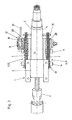
- Fig. 3
- die Lenksäule nach Fig. 1 von der Stirnseite her gesehen - Blickrichtung Pfeil A in Fig. 1;
- Fig. 4
- die am Lamellenpaket anliegende Seite einer Druckplatte und
- Fig. 5
- deren Seitensicht;
- Fig. 6
- eine Lamelle des am Mantelrohr vorgesehenen Lamellenpaketes und
- Fig. 7
- dessen Querschnitt - Schnittlinie VII - VII in Fig. 6;
- Fig. 8
- eine Lamelle des am Montageteil festgelegten Lamellenpaketes.
- Fig.1
- the steering column seen from the side;
- Fig. 2
- the steering column of Figure 1 seen from above.
- Fig. 3
- the steering column of Figure 1 seen from the front side - viewing direction arrow A in Fig. 1;
- Fig. 4
- the voltage applied to the disk pack side of a printing plate and
- Fig. 5
- their side view;
- Fig. 6
- a lamella of the jacket tube provided on the plate pack and
- Fig. 7
- its cross section - section line VII - VII in Fig. 6;
- Fig. 8
- a lamella of the set of laminations fixed to the mounting part.
Die Lenksäule nach den Fig. 1 bis 3 weist einen U-förmigen Montageteil 1 (Konsole) auf, der mit seiner planen Oberseite an einem hier nicht dargestellten Karosserieteil eines Kraftfahrzeuges festgelegt ist, und zwar zweckmäßigerweise so, daß er im Crashfall in der Zeichenebene (Fig. 1) verschiebbar ist. Da diese Lagerung nicht Gegenstand der Erfindung ist, wird sie im folgenden auch nicht näher erörtert. Die vertikalen Schenkel 3 dieses U-förmigen Montageteiles 1 (Konsole) sind nach unten gerichtet, wobei diese Schenkel 3 so ausgebildet sind, daß der Montageteil 1 sowohl in Draufsicht (Blickrichtung rechtwinkelig zur Oberseite 2 - Fig. 2) wie auch in Ansicht (Fig. 3) eine U-Form zeigt. Dabei ist die Erstreckung der Schenkel 3 parallel zur Oberseite 2 des Montageteiles 1 größer als die Erstreckung rechtwinkelig dazu.The steering column according to FIGS. 1 to 3 has a U-shaped mounting part 1 (console), which is fixed with its flat top to a body part of a motor vehicle, not shown here, and suitably so that in the event of a crash in the plane ( Fig. 1) is displaceable. Since this storage is not the subject of the invention, it will not be discussed further in the following. The
Zwischen den beiden Schenkeln 3 des Montageteiles 1 liegt ein Mantelrohr 4 mit planen parallelen Seitenflanken 5 (Fig. 3). In diesem Mantelrohr 4 ist die Lenkspindel 6 aufgenommen, die teleskopartig ausgebildet ist und die aus einem im Mantelrohr 4 festgelegten rohrartigen Teil und einem gegenüber diesem rohrartigen Teil axial verschiebbaren Schaft 7 besteht. Dieser Schaft 7 ist an seinem Ende über ein nicht näher bezeichnetes Kardangelenk 8 mit dem Lenkgetriebe verbunden. Das andere Ende 9 der Lenkspindel 6 trägt das nicht dargestellte Lenkrad.Between the two
In den Seitenflanken 5 des Mantelrohres 4, und zwar unterhalb der Lenkspindel 6, sind paarweise vorgesehene Langlochausnehmungen ausgespart, die sich parallel zur Längsachse des Mantelrohres 4 erstrecken, diese Langlochausnehmungen sind jedoch in den Figuren nicht sichtbar. Durch diese Langlochausnehmungen erstreckt sich quer zur Längsachse des Mantelrohres 4 ein Spannbolzen 10, der die Schenkel 3 des Montageteiles 1 beidseitig überragt.In the
An den Außenseiten der vertikalen Schenkel 3 sind nun mehrere, deckungsgleich geformte und voneinander distanzierte, ein Lamellenpaket 11 bildende Lamellen 12 angeordnet. Diese Lamellen 12 sind sozusagen fliegend gelagert, indem sie nur an einer ihrer Seiten 13 mit dem Montageteil 1 über Haltebolzen 14 verbunden sind. Im fliegend gelagerten Abschnitt 15 dieser Lamellen 12 ist ein vertikales Langloch 16 ausgespart (Fig. 8).On the outer sides of the
Ein zweites Lamellenpaket 17 aus im wesentlichen rechteckförmigen Lamellen 18 ist an seinen beiden Enden 19 an der Seitenflanke 5 des Mantelrohres festgelegt. Diese Enden 19 der rechteckförmigen Lamellen (Fig. 6) sind von Bolzen 29 getragen, die am Mantelrohr festgelegt sind. Zweckmäßig sind diese Lamellen auf die Bolzen 29 nur aufgefädelt, ohne mit ihnen unmittelbar verbunden zu sein. Diese rechteckförmigen Lamellen 18 besitzen ebenfalls ein Langloch 20 und diese Lamellen 18 durchsetzen sandwichartig das erstbesprochene Lamellenpaket 11, wobei sich die Langlochausnehmungen 16 und 20 der beiden Lamellenpakete 11 und 17 kreuzen und so eine Durchtrittsöffnung begrenzen, durch die der Spannbolzen 10 ragt. Unter sandwichartiger Durchsetzung der Lamellen wird hier verstanden, daß innerhalb der sich kreuzenden Lamellenpakete 11 und 17 eine Lamelle des einen Paketes auf eine Lamelle eines andren Paketes folgt, was aus den Fig. 2 und 3 ersichtlich ist. Aus Zwecken der Übersichtlichkeit sind diese sich kreuzenden Lamellen in den beiden Figuren voneinander etwas distanziert dargestellt. In der praktischen Ausführung liegen diese Lamellen unmittelbar aneinander an. Die Lamellen 12 und 18, die die Lamellenpakete 11 und 17 bilden, sind plane, ebene Metallplatten.A
Diese sich kreuzenden Lamellenpakete 11 und 17 sind beim gezeigten Ausführungsbeispiel an beiden Schenkeln 3 des Montageteiles 1 jeweils an der Außenseite vorgesehen. Der Spannbolzen 10 ist so lange bemessen, daß er diese beiden Pakete beidseitig überragt. Am einen überragenden Ende ist eine Druckplatte 21 festgelegt, die an der Außenseite der äußersten Lamelle eines Lamellenpaketes anliegt. Am andren überragenden Ende dieses Spannbolzens 10 ist ein Spannglied 22 mit einem Betätigungshebel 23 angeordnet. Dieses Spannglied 22 besteht beispielsweise aus zwei vom Spannbolzen 10 durchsetzten Scheiben 30, 31, von welchen die eine gegenüber der andren mit dem Betätigungshebel 23 verdrehbar ist, beispielsweise über einen Winkelbereich von 40° bis 45°. In der einen Scheibe sind Wälzkörper gelagert, in der andren Scheibe sind zumindest abschnittsweise schraubenflächenförmig verlaufende Abrollbahnen für die Wälzkörper vorgesehen, wobei in der Spannstellung zwischen diesen beiden Scheiben 30, 31 wirksame Arretierungs- oder Rastgliedervorgesehen sind, die den Betätigungshebel 23 in der Spannstellung festhalten. Vergleichbare Konstruktionen für solche Spannglieder sind bekannt.These intersecting disk sets 11 and 17 are provided in the embodiment shown on both
Die Druckplatte 21 besitzt an ihrer dem Lamellenpaket zugewandten Seite eine mittige Führungsleiste 24, die mit den Rändern der Langlochausnehmung 16 der außen liegenden Lamelle 12 des einen Lamellenpaketes 11 zusammenwirkt und die der Lagesicherung bzw. Verdrehsicherung dieser Druckplatte 21 dient. An ihren Ecken besitzt diese Druckplatte 21 noppenartige Erhebungen 25, die im Zusammenwirken mit den Lamellen diskrete Druckpunkte definieren. Korrespondierend zu diesen noppenartigen Erhebungen 25 an der Druckplatte 21 können an den Lamellen 12 bzw. 18 parallel zu den jeweiligen Langlochausnehmungen leistenartige Erhebungen 26 angeformt sein, so daß bei angezogenem Spannglied 22 die Lamellen 12 und 18 der beiden Lamellenpakete 11 und 17 über konstruktiv definierte, diskrete Druckpunkte aneinander anliegen. Eine derart ausgebildete Lamelle zeigen die Fig. 6 und 7.The
Bei normalem Betrieb des Kraftfahrzeuges ist das Spannglied 22 angezogen und aufgrund seiner vorstehend beschriebenen konstruktiven Ausgestaltung in seiner Lage arretiert. Der Spannbolzen 10 preßt dadurch die Lamellen der beiden Lamellenpakete 11 und 17 fest zusammen nach Art einer geschlossenen Lamallenkupplung, wodurch die eingestellte Lage der Lenksäule gesichert ist. Soll das Lenkrad verstellt werden, so betätigt der Fahrer des Kraftfahrzeuges den Betätigungshebel 23, um das Spannglied 22 zu lösen. Dadurch wird die "Lamellenkupplung" geöffnet, und das Mantelrohr 4 kann nun gegenüber dem feststehenden Montageteil 1 in seiner Längsrichtung (Pfeil 27) verschoben werden, und zwar in einem Ausmaß, das der Länge der Langlochausnehmung 20 im Lamellenpaket 17 entspricht. In den Seitenflanken 5 des Mantelrohres 4 befindet sich je eine hier nicht sichtbare Langlochausnehmung, die hinsichtlich Lage und Größe der Langlochausnehmung 20 entspricht, durch welche sich der Spannbolzen 10 erstreckt. Darüberhinaus ist es aber auch möglich, das Mantelrohr 4 mit der darin festgelegten Lenksäule nach oben oder nach unten zu verschwenken (Pfeil 28), wobei das Ausmaß dieser Schwenkbewegung durch die Länge der vertikalen Langlochausnehmungen 16 im Lamellenpaket 11 bestimmt ist. Schwenkpunkt oder Schwenkachse dieser Schwenkbewegung ist das Zentrum des Kardangelenkes 8 am andren Ende der Lenkspindel 6. Hat das Lenkrad die vom Fahrer gewünschte Lage erreicht, so wird der Betätigungshebel 23 wieder in die Spannstellung zurückgeschwenkt, in der über den Spannbolzen 10 die Lamellen der beiden Lamellenpakete fest zusammengedrückt werden.During normal operation of the motor vehicle, the clamping
Die Erfindung ist nicht auf die gezeigte Anzahl der Lamellen der Lamellenpakete beschränkt. Eventuell genügt die Anordnung eines Lamellenpaketes an einer Seite des Montageteiles 1. Zur Festlegung der Enden 19 der Lamellen 18 des einen Lamellenpaketes 17 sind am Mantelrohr 4 Bolzen 29 festgelegt, auf welchen diese Lamellen aufgefädelt sind. Um zu vermeiden, daß die aufgefädelten Lamellen eventuell Geräusche verursachen können, können die von den Bolzen 29 aufgenommenen Enden so gestaltet sein, daß sie unmittelbar aneinander anliegen, denn diese Lamellen 18 besitzen aufgrund ihrer Länge einen hinreichend großen freien Federweg, der die Verspannung mit den Lamellen 12 des andren Lamellenpaketes 11 ermöglicht. Es ist aber auch möglich, zwischen die Enden dieser Lamellen 18 gummiartige Zwischenscheiben oder Hülsen einzulegen.The invention is not limited to the number of slats of the disk packs shown. Eventually, the arrangement of a disk set on one side of the mounting
Der Spannbolzen 10 kann als Dehnschraube ausgebildet sein oder mit einem vorgespannten Federpaket gespannt werden, um eine Änderung der Klemmkraft infolge von Wärmedehnungen und damit verbundenen Längenänderungen soweit wie möglich zu unterbinden.The clamping
Beim gezeigten Ausführungsbeispiel kann das Lenkrad sowohl in der Höhe wie auch die Lenksäule in ihrer Länge verstellt werden. Dies wird u.a. dadurch erreicht, daß beide Lamellenpakete 11, 17 Langlochausnehmungen aufweisen, die sich kreuzen. Wenn eines der Lamellenpakete nur Langlochausnehmungen aufweist und das andre Lamellenpaket nur eine einfache Durchstecköffnung für den Spannbolzen, dann kann entweder nur die Lenksäule in ihrer Länge oder aber nur das Lenkrad in der Höhe verstellt werden.In the embodiment shown, the steering wheel can be adjusted in both the height and the steering column in its length. This is u.a. achieved in that both disk sets 11, 17 have slot recesses which intersect. If one of the disk packs has only Langlochausnehmungen and the other disk set only a simple insertion opening for the clamping bolt, then either only the steering column in length or only the steering wheel can be adjusted in height.
In den vorstehend beschriebenen Langlochausnehmungen, durch welche der Spannbolzen 10 ragt, können Kunststoffeinlagen vorgesehen sein, die den Spannbolzen 10 leichtgängig und geräuscharm führen. Am jeweiligen Ende der Langlochausnehmungen können Anschlagdämpfer vorgesehen werden. Die vorstehend im Zusammenhang mit den Lamellen 12 und 18 beschriebenen leistenartigen Erhöhungen 26, durch welche diskrete Druckpunkte definiert werden, können auch sinngemäß an den Seitenflanken 5 des Mantelrohres 4 und an den damit zusammenwirkenden Seiten der Schenkel 3 des Montageteiles 1 vorgesehen werden. Dank der vorstehend beschriebenen Festlegung des Mantelrohres 4 im Montageteil 1 benötigt die beschriebene Konstruktion keine zusätzliche Abstützung im Bereich des Kardangelenkes 8, da über den Spannbolzen 10 eine hinreichend große Klemmkraft erzeugt werden kann, die das Mantelrohr 4 unverrückbar festhält. Druckplatten 21 werden zweckmäßigerweise an den Außenseiten beider Lamellenpakete vorgesehen. Im gezeigten Ausführungsbeispiel sind zu beiden Seiten der Schenkel 3 des Montageteiles 1 Lamellenpakete angeordnet, die jeweils aus mehreren einzelnen Lamellen bestehen. Die Anzahl der Lamellen richtet sich nach dem jeweiligen Anwendungsfall. Es ist denkbar, daß jedes Lamellenpaket nur aus jeweils einer Lamelle besteht, so daß zu beiden Seiten des Montageteiles je zwei sich kreuzende Lamellen vorgesehen sind.In the slot recesses described above, through which the
zu den Hinweisziffern:
- 1
- Montageteil (Konsole)
- 2
- Oberseite
- 3
- vertikale Schenkel
- 4
- Mantelrohr
- 5
- Seitenflanken
- 6
- Lenkspindel
- 7
- Schaft
- 8
- Kardangelenk
- 9
- Ende
- 10
- Spannbolzen
- 11
- Lamellenpaket
- 12
- Lamelle
- 13
- Seite
- 14
- Haltebolzen
- 15
- Abschnitt
- 16
- Langlochausnehmung
- 17
- Lamellenpaket
- 18
- Lamelle
- 19
- Ende
- 20
- Langlochausnehmung
- 21
- Druckplatte
- 22
- Spannglied
- 23
- Betätigungshebel
- 24
- Führungsleiste
- 25
- noppenartige Erhöhung
- 26
- leistenartige Erhebung
- 27
- Pfeil
- 28
- Pfeil
- 29
- Bolzen
- 30
- Scheibe
- 31
- Scheibe
- 1
- Mounting part (console)
- 2
- top
- 3
- vertical thighs
- 4
- casing pipe
- 5
- side flanks
- 6
- steering shaft
- 7
- shaft
- 8th
- universal joint
- 9
- The End
- 10
- clamping bolt
- 11
- disk pack
- 12
- lamella
- 13
- page
- 14
- retaining bolt
- 15
- section
- 16
- elongate recess
- 17
- disk pack
- 18
- lamella
- 19
- The End
- 20
- elongate recess
- 21
- printing plate
- 22
- tendon
- 23
- actuating lever
- 24
- guide rail
- 25
- knob-like elevation
- 26
- strip-like elevation
- 27
- arrow
- 28
- arrow
- 29
- bolt
- 30
- disc
- 31
- disc
Claims (11)
- A steering column for motor vehicles, comprising a mounting part (1) which is fixable to a body part and between the arms (3) of which is arranged a steering-column tube (4) receiving the steering spindle (6), wherein the two flanks (5) of the steering-column tube (4), which are flat or, for the formation of discrete pressure points, have strip-type projections which co-operate with strip-type projections on the insides of the arms (3) of the mounting part (1), rest against the insides of the two arms (3) of the mounting part (1), a clamping bolt (10), arranged transversely to the axis of the steering spindle (6), extends through the steering-column tube (4) and through openings provided in the arms (3) of the mounting part (1), and mutually overlapping plates (12, 18) are provided on the outside of at least one arm (3) of the mounting part (1) and, in the overlap region, have openings (16, 20) delimiting a through hole for the clamping bolt (10), and the clamping bolt (10) carries a pressure plate (21) at one end and an adjustable clamping member (22) at the other end which together have a compressive effect on the plates (12, 18), and a set of plates (11), preferably comprising a plurality of spaced plates (12), is fixed to the outside of at least one arm (3) of the mounting part (1), and a second set of plates (17), comprising at least one plate (18), is fixed to the outside of the steering-column tube (4), and the plates (12) of the set of plates (11) arranged on the mounting part (1) and the plates (18) of the second set of plates (17) cross one another in a sandwich-type manner, characterised in that slotted openings (16, 20) are provided in the plates (12, 18) of the two sets of plates (11, 17), the aligned slotted openings (16) in the first plates (12) intersecting the aligned slotted openings (20) in the second plates (18), and the opening in the steering-column tube (4), through which the clamping bolt (10) extends, being formed as a slotted opening and being substantially aligned with the slotted openings (20) in the set of plates (17) fixed to the steering-column tube (4), and the slotted openings provided in the two arms (3) of the mounting part (1) being aligned with the slotted openings (16) in the set of plates (11) fixed to the mounting part (1), and in that, if the two flanks (5) of the steering-column tube (4) and the insides of the arms (3) of the mounting part (1) have co-operating strip-type projections, the strip-type projections on the flanks (5) of the steering-column tube (4) extend parallel to the longitudinal edges of the slotted opening in the steering-column tube (4), and the strip-type projections on the insides of the arms (3) of the mounting part (1) extend parallel to the longitudinal edges of the slotted openings in the arms (3) of the mounting part (1), and the plates (12, 18) likewise have strip-type projections (26) which project relative to the planes of the plates (12, 18) and extend parallel to the longitudinal edges of the slotted openings in the plates (12, 18), and the pressure plate (21) has, on its side facing the set of plates (11) and at its corners, protuberance-type projections (25) which form locally limited pressure points when the clamping member (22) is tightened, and the strip-type projections on the flanks (5) of the steering-column tube (4), on the insides of the arms (3) of the mounting part (1) and on the plates (12, 18) correspond to the protuberance-type projections (25) on the pressure plate (21), wherein the distance (B) between them in each case corresponds to the distance (C) between the protuberance-type projections (25) on the pressure plate (21).
- A steering column according to claim 1, characterised in that the portions (15) of the plates (12) of the one set of plates (11) provided with the aligned slotted openings (16) are mounted at one end only, in a cantilevered manner, this set of plates (11) being fixed to the outside of one arm (3) of the mounting part (1).
- A steering column according to claim 2, characterised in that the set of plates (11) having the cantilevered portions (15) is fixed to the arm (3) by at least two retaining pins (14).
- A steering column according to claim 1, characterised in that the slotted openings (16) in the set of plates (11) fixed to the mounting part (1) extend substantially vertically.
- A steering column according to claim 1, characterised in that the plates (18) of the set of plates (17) fixed to the steering-column tube (4) are formed as elongate rectangles and these plates (18) are connected at both ends (19) to the steering-column tube (4).
- A steering column according to claim 1, characterised in that, if the two flanks (5) of the steering-column tube (4) are flat, the pressure plate (21), on its side facing the set of plates (11), has protuberance-type projections (25) forming locally limited pressure points at the edges when the clamping member (22) is tightened, and in that strip-type projections (26) are provided parallel to the longitudinal edges of the slotted openings (16, 20) in the plates (12, 18) and project relative to the planes of the plates, the distance (B) between the strip-type projections (26) corresponding to the distance (C) between the protuberance-type projections (25) on the pressure plate (21).
- A steering column according to any one of claims 1 to 6, characterised in that sets of plates (11, 17), through which clamping bolts (10) extend, are arranged on the outside of both arms (3) of the mounting part (1).
- A steering column according to claim 1, characterised in that the clamping bolt (10) is formed as an expansion bolt.
- A steering column according to claim 1, characterised in that the clamping member (22) is formed in a known manner from two discs (30, 31) through which the clamping bolt (10) extends, of which the one disc (30) is fastened to the adjacent set of plates so as to be rotationally fixed, and the other disc (31) is connected to an actuating lever (23), and rolling elements are freely rotatably mounted in at least one of the two discs (30, 31) and rest against the face of the other disc, this face being formed over at least part of its circumference as a helicoidal surface, and a detent, effective in the clamped position of the clamping member (22), is provided between the discs (30, 31).
- A steering column according to claim 1, characterised in that the arms (3) of the substantially U-shaped mounting part (1), formed as a bracket, extend both at right angles to the upper surface (2) of the plate connecting the arms (3) and parallel to this upper surface (2), and the mounting part (1) is U-shaped both in plan view and in elevation (figs. 2 and 3).
- A steering column according to claim 5, characterised in that both ends (19) of the plates (18) are freely movably threaded onto pins (29) fixed to the steering-column tube (4).
Applications Claiming Priority (3)
| Application Number | Priority Date | Filing Date | Title |
|---|---|---|---|
| AT70296 | 1996-04-18 | ||
| AT702/96 | 1996-04-18 | ||
| AT70296 | 1996-04-18 |
Publications (3)
| Publication Number | Publication Date |
|---|---|
| EP0802104A1 EP0802104A1 (en) | 1997-10-22 |
| EP0802104B1 EP0802104B1 (en) | 2001-06-27 |
| EP0802104B2 true EP0802104B2 (en) | 2006-10-25 |
Family
ID=3497567
Family Applications (1)
| Application Number | Title | Priority Date | Filing Date |
|---|---|---|---|
| EP97105348A Expired - Lifetime EP0802104B2 (en) | 1996-04-18 | 1997-03-29 | Steering column for motor vehicles |
Country Status (9)
| Country | Link |
|---|---|
| US (1) | US6095012A (en) |
| EP (1) | EP0802104B2 (en) |
| JP (1) | JP3939806B2 (en) |
| KR (1) | KR100479313B1 (en) |
| AR (1) | AR006691A1 (en) |
| BR (1) | BR9700566A (en) |
| CA (1) | CA2203027C (en) |
| DE (1) | DE59703886D1 (en) |
| ES (1) | ES2162146T5 (en) |
Families Citing this family (84)
| Publication number | Priority date | Publication date | Assignee | Title |
|---|---|---|---|---|
| US5972476A (en) * | 1997-11-21 | 1999-10-26 | Means Industries, Inc. | Laminated parts and method of making same |
| SE521827C2 (en) * | 1998-11-27 | 2003-12-09 | Volvo Personvagnar Ab | Arrangements for steering |
| DE19933674B4 (en) * | 1999-07-17 | 2005-07-21 | Daimlerchrysler Ag | Adjustment mechanism for a steering column of a motor vehicle |
| DE19933677B4 (en) * | 1999-07-17 | 2005-10-27 | Daimlerchrysler Ag | Steering system for a motor vehicle |
| DE19933678C2 (en) | 1999-07-17 | 2001-05-23 | Daimler Chrysler Ag | Adjustment device for a casing pipe of a steering system of a motor vehicle |
| EP1222043B1 (en) * | 1999-10-20 | 2004-06-16 | Adval Tech Holding AG | Method for the production of lamella packets for adjustable steering columns |
| EP1106848A1 (en) | 1999-12-06 | 2001-06-13 | Straub Werke AG | Sleeve |
| DE10031721C1 (en) * | 2000-06-29 | 2001-12-13 | Krupp Presta Ag Eschen | Length and height adjustment device for automobile steering column has locking devices for length and height adjustment opened and closed in common by clamping mechanism |
| JP3431886B2 (en) * | 2000-07-07 | 2003-07-28 | 株式会社山田製作所 | Steering position adjustment device |
| US6923086B2 (en) * | 2001-02-06 | 2005-08-02 | Thyssenkrupp Presta Ag | Safety device for a motor vehicle with a steering column arrangement and safety method |
| DE50115355D1 (en) * | 2001-02-06 | 2010-04-01 | Thyssenkrupp Presta Ag | COLUMN ARRANGEMENT FOR ONE VEHICLE |
| JP2002362377A (en) * | 2001-06-01 | 2002-12-18 | Nsk Ltd | Steering column holding device for vehicle |
| GB2377471A (en) * | 2001-07-13 | 2003-01-15 | Nsk Steering Sys Europ Ltd | Clamping apparatus with zinc coated clutch plates |
| JP2003118595A (en) | 2001-08-06 | 2003-04-23 | Nsk Ltd | Vehicular steering device and its manufacturing method |
| DE10161849B4 (en) * | 2001-12-15 | 2010-09-02 | Daimler Ag | Clamp mechanism for an adjustable steering column |
| US6460427B1 (en) | 2002-01-28 | 2002-10-08 | Ford Global Technologies, Inc. | Adjustment linkage for tilting and telescoping a steering column assembly |
| US7047836B2 (en) * | 2002-02-01 | 2006-05-23 | Trw Inc. | Surface treatment for a locking mechanism |
| DE10232041A1 (en) * | 2002-07-16 | 2004-02-05 | Thyssenkrupp Presta Ag | steering column |
| GB2392971A (en) * | 2002-09-10 | 2004-03-17 | Nsk Steering Sys Europ Ltd | Clamping apparatus for an adjustable steering column for a vehicle |
| CN1726572A (en) * | 2002-12-13 | 2006-01-25 | 高田-彼得里公司 | Steering column module |
| DE10261538A1 (en) * | 2002-12-23 | 2004-07-01 | Thyssenkrupp Presta Ag | steering column |
| DE10318034B4 (en) * | 2003-04-19 | 2012-01-19 | Fred Eggers | Clamping device for the steering column of a motor vehicle |
| DE10333228A1 (en) | 2003-07-21 | 2005-02-24 | Thyssenkrupp Presta Ag | Locking device of an adjustable in at least one adjustment steering column |
| DE10341704B4 (en) | 2003-09-10 | 2008-10-30 | Daimler Ag | Steering column assembly with a variable in their inclination and length steering column |
| DE102004024876B4 (en) * | 2003-09-10 | 2009-04-09 | Daimler Ag | Steering column assembly with a variable in their inclination and length steering column |
| WO2005028281A1 (en) * | 2003-09-10 | 2005-03-31 | Daimlerchrysler Ag | Steering column assembly comprising a steering column the tilt and length of which can be modified |
| DE10341604B4 (en) * | 2003-09-10 | 2008-08-28 | Daimler Ag | Steering column assembly with a variable in their inclination and length steering column |
| DE10343399B3 (en) * | 2003-09-19 | 2005-03-17 | Daimlerchrysler Ag | Steering column unit for motor vehicle has steering column connected to bracket via bracket slide and has operating element to release and lock clamps |
| WO2005037627A1 (en) * | 2003-10-20 | 2005-04-28 | Nsk Ltd. | Steering device |
| US20060107784A1 (en) * | 2003-12-16 | 2006-05-25 | Takata-Petri, Inc. | Steering column module |
| DE102004007554B4 (en) * | 2004-02-17 | 2008-10-02 | Daimler Ag | Steering column assembly for a motor vehicle |
| JP4848954B2 (en) * | 2004-06-01 | 2011-12-28 | 日本精工株式会社 | Tilt-type steering device for vehicle |
| DE102004046073A1 (en) * | 2004-09-23 | 2006-03-16 | Daimlerchrysler Ag | Steering column arrangement for motor vehicle, has piston cylinder unit provided for positional fixation of steering column, and including two volume-variable chambers filled with electrorheological or magnetorheological fluid |
| DE102004051060B3 (en) * | 2004-10-19 | 2006-01-26 | Thyssenkrupp Presta Ag | Adjustable steering column of a motor vehicle |
| SE528001C2 (en) * | 2004-12-22 | 2006-08-01 | Fuji Autotech Ab | Steering wheel mechanism for motor vehicles |
| EP1884444B1 (en) | 2005-05-06 | 2017-03-08 | NSK Ltd. | Steering column device |
| DE102005035009B3 (en) * | 2005-07-22 | 2006-12-14 | Thyssenkrupp Presta Ag | Adjustable steering column for motor vehicle, has segment that lies in area of recess in closed condition of fixing unit during through-slipping of operating unit, extends into recess and lies opposite to edge of recess |
| DE102005036582A1 (en) * | 2005-08-01 | 2007-02-08 | Thyssenkrupp Presta Ag | Adjustable steering column for a motor vehicle |
| DE602006001334D1 (en) * | 2005-09-08 | 2008-07-10 | Nsk Ltd | steering device |
| JP4622756B2 (en) * | 2005-09-08 | 2011-02-02 | 日本精工株式会社 | Steering wheel position adjusting device and manufacturing method of friction plate unit for the position adjusting device |
| EP1931553B1 (en) * | 2005-10-05 | 2009-12-02 | ThyssenKrupp Presta Aktiengesellschaft | Steering column for a motor vehicle |
| DE102005052123B3 (en) * | 2005-10-28 | 2007-01-11 | Thyssenkrupp Presta Ag | Steering column for a vehicle comprises a support unit having side parts lying on both sides of an adjusting unit |
| JP5131425B2 (en) | 2005-11-21 | 2013-01-30 | 日本精工株式会社 | Steering column device |
| DE102005056308B3 (en) * | 2005-11-24 | 2007-03-29 | Thyssenkrupp Presta Ag | Adjustable steering column for motor vehicle, has adjusting unit adjustable opposite to retaining unit to adjust position of column in opened condition of fixing device, and blocking unit connected with retaining unit |
| DE102006007553B3 (en) * | 2006-02-16 | 2007-05-16 | Thyssenkrupp Presta Ag | Adjustable steering column for motor vehicle, has supporting part which is designed in form of plane plate and connection takes place with casing unit and side walls by bolt passing through long hole |
| DE102006009304B3 (en) * | 2006-03-01 | 2007-07-26 | Daimlerchrysler Ag | Steering column arrangement for vehicles, has console and steering column, where lamella is pivoted towards longitudinal middle axis, in fixed condition of steering column acting in transverse direction to longitudinal axis |
| DE102006028491B4 (en) * | 2006-06-21 | 2008-04-03 | Daimler Ag | clamping device |
| DE102006034715B3 (en) * | 2006-07-27 | 2008-04-03 | Daimler Ag | Clamping mechanism for adjustable steering column of motor vehicle, has clamping unit combining with another clamping unit and held guided to lamella arrangement, where arrangement is assigned to column pipe of steering shaft by cam-locks |
| GB2441549B (en) * | 2006-09-05 | 2009-05-13 | Nsk Steering Sys Europ Ltd | Toothed cam clamping device for adjustable steering column |
| JP5070795B2 (en) | 2006-10-19 | 2012-11-14 | 日本精工株式会社 | Steering wheel position adjustment device |
| US8091449B2 (en) * | 2006-12-15 | 2012-01-10 | Nsk Ltd. | Steering apparatus |
| DE102007003091B3 (en) | 2007-01-16 | 2008-08-07 | Thyssenkrupp Presta Ag | Adjustable steering column for a motor vehicle |
| JP4567040B2 (en) * | 2007-09-07 | 2010-10-20 | 本田技研工業株式会社 | Tilt telescopic steering device |
| DE102008016742B4 (en) | 2008-03-31 | 2010-01-14 | Thyssenkrupp Presta Ag | Steering column for a motor vehicle |
| DE102008034807B3 (en) * | 2008-07-24 | 2009-10-01 | Thyssenkrupp Presta Ag | Steering column for a motor vehicle |
| JP5226582B2 (en) * | 2009-03-30 | 2013-07-03 | 株式会社山田製作所 | Steering device |
| KR101034631B1 (en) * | 2009-06-01 | 2011-05-16 | 동서콘트롤(주) | Telescopic Device Of Steering Column For Vehicle |
| JP5227904B2 (en) * | 2009-06-24 | 2013-07-03 | 富士機工株式会社 | Steering column device |
| DE102009038317B4 (en) | 2009-08-21 | 2016-12-29 | Thyssenkrupp Presta Aktiengesellschaft | Adjustable steering column for a motor vehicle |
| DE102009059159B3 (en) | 2009-12-16 | 2011-01-27 | Thyssenkrupp Presta Ag | Steering column for motor vehicle, has casing unit that is pretensioned by bending wire with respect to support part when unit is moved parallel to longitudinal axis of steering shaft toward vehicle front |
| JP2011157015A (en) † | 2010-02-02 | 2011-08-18 | Fuji Kiko Co Ltd | Steering column device |
| DE102010036894A1 (en) | 2010-05-25 | 2011-12-01 | Thyssenkrupp Presta Ag | spring body |
| DE102010036891A1 (en) | 2010-06-28 | 2011-12-29 | Thyssenkrupp Presta Ag | Adjustable steering column for a motor vehicle |
| DE102010061268A1 (en) | 2010-12-15 | 2012-06-21 | Thyssenkrupp Presta Ag | Steering column for a motor vehicle |
| DE102011000319B3 (en) * | 2011-01-25 | 2012-05-24 | Thyssenkrupp Presta Ag | Locking device for locking a steering shaft bearing unit |
| CN104908801B (en) | 2011-02-25 | 2017-08-01 | 日本精工株式会社 | Telescopic steering apparatus |
| JP5626165B2 (en) * | 2011-06-15 | 2014-11-19 | 日本精工株式会社 | Steering device |
| JP5447556B2 (en) * | 2011-06-15 | 2014-03-19 | 日本精工株式会社 | Steering device |
| JP5966290B2 (en) * | 2011-09-20 | 2016-08-10 | 日本精工株式会社 | Steering device |
| US8869645B2 (en) * | 2011-11-15 | 2014-10-28 | Steering Solutions Ip Holding Corporation | Linear travel adjustment assembly |
| DE102011055410A1 (en) | 2011-11-16 | 2013-05-16 | Thyssenkrupp Presta Aktiengesellschaft | Locking device for an adjustable steering column for a motor vehicle |
| JP5845959B2 (en) * | 2011-12-15 | 2016-01-20 | 日本精工株式会社 | Telescopic steering device |
| DE102011057104B4 (en) | 2011-12-28 | 2016-03-10 | Thyssenkrupp Presta Aktiengesellschaft | Locking device for an adjustable steering column |
| DE102012100486B3 (en) | 2012-01-20 | 2013-02-28 | Thyssenkrupp Presta Aktiengesellschaft | Steering column for motor vehicle, has damping device damping pivoting movement of operating lever about pivot axis, where damping device is arranged on side of support part opposite to operating lever |
| DE102012102556B3 (en) | 2012-03-26 | 2013-06-27 | Thyssenkrupp Presta Aktiengesellschaft | Plug-in body for a clamping bolt |
| JP5895754B2 (en) * | 2012-07-17 | 2016-03-30 | 日本精工株式会社 | Steering wheel position adjustment device |
| JP5929616B2 (en) * | 2012-08-10 | 2016-06-08 | 日本精工株式会社 | Steering wheel position adjustment device |
| EP3045377B1 (en) | 2014-01-07 | 2018-11-14 | NSK Ltd. | Position adjustment device for steering wheel |
| GB201412973D0 (en) * | 2014-07-22 | 2014-09-03 | Trw Ltd | Adjustable steering columns |
| DE102015112086B4 (en) * | 2015-07-24 | 2022-10-20 | Robert Bosch Automotive Steering Gmbh | DEVICE FOR ADJUSTING A STEERING COLUMN OF A MOTOR VEHICLE AND STEERING SYSTEM |
| WO2018209183A1 (en) * | 2017-05-11 | 2018-11-15 | R.H. Sheppard Co., Inc. | Steering column assembly |
| DE102017219914B4 (en) * | 2017-11-09 | 2019-07-18 | Thyssenkrupp Ag | Steering column for a motor vehicle |
| GB2576496B (en) * | 2018-07-25 | 2022-11-23 | Trw Steering Systems Poland Sp Z O O | A steering column assembly |
| RU2709061C1 (en) * | 2018-12-13 | 2019-12-13 | Публичное акционерное общество "Чебоксарский завод промышленных тракторов" (ПАО "Промтрактор") | Vehicle steering column |
Family Cites Families (23)
| Publication number | Priority date | Publication date | Assignee | Title |
|---|---|---|---|---|
| DE1780061C3 (en) * | 1968-07-27 | 1979-05-17 | Daimler-Benz Ag, 7000 Stuttgart | Safety steering device for motor vehicles |
| JPS5019124U (en) * | 1973-06-18 | 1975-03-04 | ||
| FR2360454A1 (en) * | 1976-08-05 | 1978-03-03 | Chrysler France | Adjustable car steering column assembly - has movable steering column support and fixed support on car, both supports having slots for adjusting rake and length |
| JPS5551664A (en) * | 1978-10-11 | 1980-04-15 | Nissan Motor Co Ltd | Tilt angle adjusting apparatus of tilt handle |
| FR2456652A1 (en) | 1979-05-16 | 1980-12-12 | Renault Vehicules Ind | ADJUSTABLE STEERING COLUMN FOR A ROAD VEHICLE |
| GB2092966A (en) * | 1981-02-13 | 1982-08-25 | Ford Motor Co | Steering column assembly |
| JPS5989767U (en) * | 1982-12-09 | 1984-06-18 | 三菱自動車工業株式会社 | Fixing device for movable steering column |
| SE449329B (en) * | 1983-02-23 | 1987-04-27 | Ffv Affersverket | ADJUSTABLE STEERING BARS |
| DE3619125C1 (en) * | 1986-06-06 | 1987-10-22 | Daimler Benz Ag | Receiving device for an adjustable steering column of a motor vehicle |
| JPH0260073U (en) * | 1988-10-27 | 1990-05-02 | ||
| SE8803943D0 (en) | 1988-10-31 | 1988-10-31 | Ffv Autotech Ab | STEERING MOUNTING PARTS WITH SLIDING AND TIP FUNCTION |
| JPH02124763U (en) * | 1989-03-24 | 1990-10-15 | ||
| SE465563B (en) | 1989-10-31 | 1991-09-30 | Volvo Ab | ADJUSTABLE VEHICLE |
| US5117707A (en) * | 1990-02-23 | 1992-06-02 | Fuji Kiko Company, Limited | Tilting steering column |
| DE4016163C2 (en) * | 1990-05-19 | 1994-03-10 | Reiche & Co | Device for adjusting the angular position of a motor vehicle steering column |
| JP2989680B2 (en) * | 1991-02-15 | 1999-12-13 | 株式会社山田製作所 | Tilt and telescopic steering system |
| GB2273338A (en) * | 1992-12-02 | 1994-06-15 | Torrington Co | Steering column clamping mechanism. |
| DE59400137D1 (en) * | 1993-01-07 | 1996-04-11 | Lemfoerder Metallwaren Ag | Clamping device for an adjustable steering column in a motor vehicle |
| JP3094053B2 (en) * | 1994-02-25 | 2000-10-03 | 富士機工株式会社 | Vehicle steering system |
| SE502558C2 (en) * | 1994-03-09 | 1995-11-13 | Fuji Autotech Ab | Telescopic and swivel steering column bracket |
| US5481938A (en) * | 1994-05-02 | 1996-01-09 | General Motors Corporation | Position control apparatus for steering column |
| US5722299A (en) * | 1994-06-30 | 1998-03-03 | Fuji Kiko Co., Ltd. | Adjustable steering column assembly for a vehicle |
| GB2306629A (en) | 1995-10-28 | 1997-05-07 | Nastech Europ Ltd | Adjustable vehicle steering column assembly |
-
1997
- 1997-03-26 US US08/824,376 patent/US6095012A/en not_active Expired - Lifetime
- 1997-03-29 EP EP97105348A patent/EP0802104B2/en not_active Expired - Lifetime
- 1997-03-29 DE DE59703886T patent/DE59703886D1/en not_active Expired - Lifetime
- 1997-03-29 ES ES97105348T patent/ES2162146T5/en not_active Expired - Lifetime
- 1997-04-17 BR BR9700566A patent/BR9700566A/en not_active IP Right Cessation
- 1997-04-17 CA CA002203027A patent/CA2203027C/en not_active Expired - Lifetime
- 1997-04-17 JP JP10058197A patent/JP3939806B2/en not_active Expired - Lifetime
- 1997-04-17 KR KR1019970014251A patent/KR100479313B1/en not_active IP Right Cessation
- 1997-04-18 AR ARP970101563A patent/AR006691A1/en unknown
Also Published As
| Publication number | Publication date |
|---|---|
| ES2162146T3 (en) | 2001-12-16 |
| EP0802104A1 (en) | 1997-10-22 |
| KR970069741A (en) | 1997-11-07 |
| JPH1035511A (en) | 1998-02-10 |
| AR006691A1 (en) | 1999-09-08 |
| BR9700566A (en) | 1998-09-29 |
| CA2203027C (en) | 2005-03-29 |
| ES2162146T5 (en) | 2007-06-01 |
| US6095012A (en) | 2000-08-01 |
| KR100479313B1 (en) | 2005-07-11 |
| EP0802104B1 (en) | 2001-06-27 |
| CA2203027A1 (en) | 1997-10-18 |
| JP3939806B2 (en) | 2007-07-04 |
| DE59703886D1 (en) | 2001-08-02 |
Similar Documents
| Publication | Publication Date | Title |
|---|---|---|
| EP0802104B2 (en) | Steering column for motor vehicles | |
| EP0836981B1 (en) | Device for adjusting the length and the inclination of a motor vehicle steering column | |
| EP1500570B1 (en) | Locking device of an adjustable steering column in at least one adjustment direction | |
| EP1384644B1 (en) | Device for adjusting the reach and height of the steering column of a vehicle | |
| DE3212842C2 (en) | ||
| DE3837190C1 (en) | ||
| EP0245612B1 (en) | Steering column attachment in a vehicle | |
| EP2512899B1 (en) | Steering column for a motor vehicle | |
| EP0254808B1 (en) | Headrest for automotive vehicles, adjustable in height and inclination, provided with a central window | |
| EP1590226B1 (en) | Clamping device for a steering column | |
| EP1433687B1 (en) | Steering column | |
| EP3529127B1 (en) | Steering column comprising an energy absorption device for a motor vehicle | |
| EP1910148A1 (en) | Adjustable steering column for a motor vehicle | |
| EP1917176A1 (en) | Adjustable steering column for a motor vehicle | |
| DE19745016C2 (en) | Deflection fitting for seat belts of vehicles, in particular motor vehicles | |
| EP1984227B1 (en) | Adjustable steering column for a motor vehicle | |
| WO2006024459A1 (en) | Steering-column assembly | |
| DE19859238A1 (en) | Motor vehicle seat has damping element as separate component and connected to seat and longitudinal adjustment rail by element formed by threaded rod, rotatable nut and sleeve-form component | |
| EP0912386A1 (en) | Device for locking an adjustable steering column, especially for motor vehicles | |
| DE69907723T2 (en) | ARRANGEMENT FOR A STEERING | |
| EP1296868B1 (en) | Fixing device for a steering shaft, whose height and/or length can be adjusted | |
| EP1382509B1 (en) | Steering column | |
| DE10313470B3 (en) | Steering column device for vehicle to collapse under crash energy has both deforming elements fitted on connecting element | |
| DE19720856C2 (en) | Pedestrian step designed for motor vehicles | |
| EP0128111B1 (en) | Longitudinal adjusting arrangement for vehicle seats with a power-operated adjusting device and a longitudinal guide |
Legal Events
| Date | Code | Title | Description |
|---|---|---|---|
| PUAI | Public reference made under article 153(3) epc to a published international application that has entered the european phase |
Free format text: ORIGINAL CODE: 0009012 |
|
| AK | Designated contracting states |
Kind code of ref document: A1 Designated state(s): DE ES FR GB IT SE |
|
| 17P | Request for examination filed |
Effective date: 19971122 |
|
| TPAD | Observations filed by third parties |
Free format text: ORIGINAL CODE: EPIDOS TIPA |
|
| 17Q | First examination report despatched |
Effective date: 19990414 |
|
| GBC | Gb: translation of claims filed (gb section 78(7)/1977) | ||
| GRAG | Despatch of communication of intention to grant |
Free format text: ORIGINAL CODE: EPIDOS AGRA |
|
| GRAG | Despatch of communication of intention to grant |
Free format text: ORIGINAL CODE: EPIDOS AGRA |
|
| GRAG | Despatch of communication of intention to grant |
Free format text: ORIGINAL CODE: EPIDOS AGRA |
|
| GRAH | Despatch of communication of intention to grant a patent |
Free format text: ORIGINAL CODE: EPIDOS IGRA |
|
| GRAH | Despatch of communication of intention to grant a patent |
Free format text: ORIGINAL CODE: EPIDOS IGRA |
|
| GRAA | (expected) grant |
Free format text: ORIGINAL CODE: 0009210 |
|
| AK | Designated contracting states |
Kind code of ref document: B1 Designated state(s): DE ES FR GB IT SE |
|
| REF | Corresponds to: |
Ref document number: 59703886 Country of ref document: DE Date of ref document: 20010802 |
|
| ITF | It: translation for a ep patent filed |
Owner name: A. BRE. MAR. S.R.L. |
|
| GBT | Gb: translation of ep patent filed (gb section 77(6)(a)/1977) |
Effective date: 20010928 |
|
| ET | Fr: translation filed | ||
| REG | Reference to a national code |
Ref country code: ES Ref legal event code: FG2A Ref document number: 2162146 Country of ref document: ES Kind code of ref document: T3 |
|
| REG | Reference to a national code |
Ref country code: GB Ref legal event code: IF02 |
|
| PLBQ | Unpublished change to opponent data |
Free format text: ORIGINAL CODE: EPIDOS OPPO |
|
| PLBQ | Unpublished change to opponent data |
Free format text: ORIGINAL CODE: EPIDOS OPPO |
|
| PLBI | Opposition filed |
Free format text: ORIGINAL CODE: 0009260 |
|
| PLAB | Opposition data, opponent's data or that of the opponent's representative modified |
Free format text: ORIGINAL CODE: 0009299OPPO |
|
| PLBQ | Unpublished change to opponent data |
Free format text: ORIGINAL CODE: EPIDOS OPPO |
|
| PLBQ | Unpublished change to opponent data |
Free format text: ORIGINAL CODE: EPIDOS OPPO |
|
| PLAB | Opposition data, opponent's data or that of the opponent's representative modified |
Free format text: ORIGINAL CODE: 0009299OPPO |
|
| PLBF | Reply of patent proprietor to notice(s) of opposition |
Free format text: ORIGINAL CODE: EPIDOS OBSO |
|
| PLBF | Reply of patent proprietor to notice(s) of opposition |
Free format text: ORIGINAL CODE: EPIDOS OBSO |
|
| 26 | Opposition filed |
Opponent name: NSK STEERING SYSTEMS EUROPE LIMITED Effective date: 20020327 Opponent name: DAIMLERCHRYSLER AG Effective date: 20020326 |
|
| R26 | Opposition filed (corrected) |
Opponent name: DAIMLERCHRYSLER AG * 20020327 NSK STEERING SYSTEMS Effective date: 20020326 |
|
| R26 | Opposition filed (corrected) |
Opponent name: DAIMLERCHRYSLER AG * 20020327 NSK STEERING SYSTEMS Effective date: 20020326 |
|
| PLBF | Reply of patent proprietor to notice(s) of opposition |
Free format text: ORIGINAL CODE: EPIDOS OBSO |
|
| PLBF | Reply of patent proprietor to notice(s) of opposition |
Free format text: ORIGINAL CODE: EPIDOS OBSO |
|
| APBP | Date of receipt of notice of appeal recorded |
Free format text: ORIGINAL CODE: EPIDOSNNOA2O |
|
| APBP | Date of receipt of notice of appeal recorded |
Free format text: ORIGINAL CODE: EPIDOSNNOA2O |
|
| APBQ | Date of receipt of statement of grounds of appeal recorded |
Free format text: ORIGINAL CODE: EPIDOSNNOA3O |
|
| APAA | Appeal reference recorded |
Free format text: ORIGINAL CODE: EPIDOS REFN |
|
| APAH | Appeal reference modified |
Free format text: ORIGINAL CODE: EPIDOSCREFNO |
|
| APBU | Appeal procedure closed |
Free format text: ORIGINAL CODE: EPIDOSNNOA9O |
|
| PUAH | Patent maintained in amended form |
Free format text: ORIGINAL CODE: 0009272 |
|
| STAA | Information on the status of an ep patent application or granted ep patent |
Free format text: STATUS: PATENT MAINTAINED AS AMENDED |
|
| 27A | Patent maintained in amended form |
Effective date: 20061025 |
|
| AK | Designated contracting states |
Kind code of ref document: B2 Designated state(s): DE ES FR GB IT SE |
|
| GBTA | Gb: translation of amended ep patent filed (gb section 77(6)(b)/1977) | ||
| REG | Reference to a national code |
Ref country code: SE Ref legal event code: RPEO |
|
| ET3 | Fr: translation filed ** decision concerning opposition | ||
| REG | Reference to a national code |
Ref country code: ES Ref legal event code: DC2A Date of ref document: 20070118 Kind code of ref document: T5 |
|
| PG25 | Lapsed in a contracting state [announced via postgrant information from national office to epo] |
Ref country code: DE Free format text: LAPSE BECAUSE OF NON-PAYMENT OF DUE FEES Effective date: 20111001 |
|
| REG | Reference to a national code |
Ref country code: FR Ref legal event code: PLFP Year of fee payment: 20 |
|
| PGFP | Annual fee paid to national office [announced via postgrant information from national office to epo] |
Ref country code: GB Payment date: 20160331 Year of fee payment: 20 Ref country code: SE Payment date: 20160329 Year of fee payment: 20 Ref country code: FR Payment date: 20160330 Year of fee payment: 20 |
|
| PGFP | Annual fee paid to national office [announced via postgrant information from national office to epo] |
Ref country code: DE Payment date: 20160525 Year of fee payment: 20 Ref country code: ES Payment date: 20160422 Year of fee payment: 20 |
|
| PG25 | Lapsed in a contracting state [announced via postgrant information from national office to epo] |
Ref country code: IT Free format text: LAPSE BECAUSE OF NON-PAYMENT OF DUE FEES Effective date: 20160329 |
|
| REG | Reference to a national code |
Ref country code: DE Ref legal event code: R071 Ref document number: 59703886 Country of ref document: DE |
|
| REG | Reference to a national code |
Ref country code: GB Ref legal event code: PE20 Expiry date: 20170328 |
|
| REG | Reference to a national code |
Ref country code: SE Ref legal event code: EUG |
|
| PG25 | Lapsed in a contracting state [announced via postgrant information from national office to epo] |
Ref country code: GB Free format text: LAPSE BECAUSE OF EXPIRATION OF PROTECTION Effective date: 20170328 |
|
| PG25 | Lapsed in a contracting state [announced via postgrant information from national office to epo] |
Ref country code: IT Free format text: LAPSE BECAUSE OF NON-PAYMENT OF DUE FEES Effective date: 20160329 |
|
| PGFP | Annual fee paid to national office [announced via postgrant information from national office to epo] |
Ref country code: IT Payment date: 20160325 Year of fee payment: 20 |
|
| PGRI | Patent reinstated in contracting state [announced from national office to epo] |
Ref country code: IT Effective date: 20170817 |
|
| REG | Reference to a national code |
Ref country code: ES Ref legal event code: FD2A Effective date: 20180508 |
|
| PG25 | Lapsed in a contracting state [announced via postgrant information from national office to epo] |
Ref country code: ES Free format text: LAPSE BECAUSE OF EXPIRATION OF PROTECTION Effective date: 20170330 |