EP0801489A2 - Hinge mechanism for fastening the two parts of a foldable apparatus to one another - Google Patents
Hinge mechanism for fastening the two parts of a foldable apparatus to one another Download PDFInfo
- Publication number
- EP0801489A2 EP0801489A2 EP97660034A EP97660034A EP0801489A2 EP 0801489 A2 EP0801489 A2 EP 0801489A2 EP 97660034 A EP97660034 A EP 97660034A EP 97660034 A EP97660034 A EP 97660034A EP 0801489 A2 EP0801489 A2 EP 0801489A2
- Authority
- EP
- European Patent Office
- Prior art keywords
- hinge
- hinge pin
- lug
- pin
- end surface
- Prior art date
- Legal status (The legal status is an assumption and is not a legal conclusion. Google has not performed a legal analysis and makes no representation as to the accuracy of the status listed.)
- Withdrawn
Links
Images


Classifications
-
- H—ELECTRICITY
- H04—ELECTRIC COMMUNICATION TECHNIQUE
- H04M—TELEPHONIC COMMUNICATION
- H04M1/00—Substation equipment, e.g. for use by subscribers
- H04M1/02—Constructional features of telephone sets
- H04M1/0202—Portable telephone sets, e.g. cordless phones, mobile phones or bar type handsets
- H04M1/0206—Portable telephones comprising a plurality of mechanically joined movable body parts, e.g. hinged housings
- H04M1/0208—Portable telephones comprising a plurality of mechanically joined movable body parts, e.g. hinged housings characterized by the relative motions of the body parts
- H04M1/0214—Foldable telephones, i.e. with body parts pivoting to an open position around an axis parallel to the plane they define in closed position
- H04M1/0216—Foldable in one direction, i.e. using a one degree of freedom hinge
-
- E—FIXED CONSTRUCTIONS
- E05—LOCKS; KEYS; WINDOW OR DOOR FITTINGS; SAFES
- E05D—HINGES OR SUSPENSION DEVICES FOR DOORS, WINDOWS OR WINGS
- E05D11/00—Additional features or accessories of hinges
- E05D11/06—Devices for limiting the opening movement of hinges
-
- E—FIXED CONSTRUCTIONS
- E05—LOCKS; KEYS; WINDOW OR DOOR FITTINGS; SAFES
- E05D—HINGES OR SUSPENSION DEVICES FOR DOORS, WINDOWS OR WINGS
- E05D11/00—Additional features or accessories of hinges
- E05D11/10—Devices for preventing movement between relatively-movable hinge parts
- E05D11/1028—Devices for preventing movement between relatively-movable hinge parts for maintaining the hinge in two or more positions, e.g. intermediate or fully open
- E05D11/1078—Devices for preventing movement between relatively-movable hinge parts for maintaining the hinge in two or more positions, e.g. intermediate or fully open the maintaining means acting parallel to the pivot
-
- E—FIXED CONSTRUCTIONS
- E05—LOCKS; KEYS; WINDOW OR DOOR FITTINGS; SAFES
- E05F—DEVICES FOR MOVING WINGS INTO OPEN OR CLOSED POSITION; CHECKS FOR WINGS; WING FITTINGS NOT OTHERWISE PROVIDED FOR, CONCERNED WITH THE FUNCTIONING OF THE WING
- E05F1/00—Closers or openers for wings, not otherwise provided for in this subclass
- E05F1/08—Closers or openers for wings, not otherwise provided for in this subclass spring-actuated, e.g. for horizontally sliding wings
- E05F1/10—Closers or openers for wings, not otherwise provided for in this subclass spring-actuated, e.g. for horizontally sliding wings for swinging wings, e.g. counterbalance
- E05F1/12—Mechanisms in the shape of hinges or pivots, operated by springs
- E05F1/1207—Mechanisms in the shape of hinges or pivots, operated by springs with a coil spring parallel with the pivot axis
- E05F1/1223—Mechanisms in the shape of hinges or pivots, operated by springs with a coil spring parallel with the pivot axis with a compression or traction spring
-
- E—FIXED CONSTRUCTIONS
- E05—LOCKS; KEYS; WINDOW OR DOOR FITTINGS; SAFES
- E05Y—INDEXING SCHEME RELATING TO HINGES OR OTHER SUSPENSION DEVICES FOR DOORS, WINDOWS OR WINGS AND DEVICES FOR MOVING WINGS INTO OPEN OR CLOSED POSITION, CHECKS FOR WINGS AND WING FITTINGS NOT OTHERWISE PROVIDED FOR, CONCERNED WITH THE FUNCTIONING OF THE WING
- E05Y2900/00—Application of doors, windows, wings or fittings thereof
- E05Y2900/60—Application of doors, windows, wings or fittings thereof for other use
- E05Y2900/606—Application of doors, windows, wings or fittings thereof for other use for electronic devices
Definitions
- the invention relates to a hinge mechanism according to the preamble of Claim 1.
- a hinge mechanism like this is used particularly in mobile phones and different electronic manual devices.
- the two parts of the device must be turned to the open position, in which position the parts are at a predetermined angle towards one another.
- the device stays in the open position by means of the slots and ridges of the hinge. It is desirable that the device is stable in the open position when it is used and does not close too easily.
- a force is to be exerted on the folding part, and the exerted force must be stronger than the spring force of the hinge. With regard to ease of operation of the device, the force should be neither too strong nor too weak.
- a hinge mechanism is known from the patent specification EP-535 912, in which the force required to open and to close the device is adjusted at different strengths depending on whether the device is being opened or closed.
- the device When the device is opened, it is settled at a certain predetermined angle in which the slots and ridges of the hinge mechanism meet one another. From this position, the device can be opened to a larger angle and folded to a closed position. A stronger force is needed to open the device further than to close it.
- the strength of the force needed is adjusted by means of the shape of the slots and ridges formed in the hinge lug and the locking piece that is in contact with it by means of a spring.
- angles of the inclined sides of the slot and ridge which have a trapezoidal cross-section, are applied such that in the direction of rotation of the folding movement the pulling angle is wider than in the direction of rotation of the opening movement.
- a stronger force is required to overcome the spring force to open the device further than to close it.
- the relative strength of the forces needed is adjusted by means of the angles.
- the opening angle can be widened by using more force.
- the object of this invention is to achieve a hinge mechanism which is locked to a predetermined opening angle and cannot be opened beyond that point.
- Another object of the invention is to achieve a hinge mechanism the rigidity of which can be adjusted by simple measures.
- a hinge mechanism which is mainly characterized in that the hinge pin is divided into two parts, the first of which is form-locked in axial transition to the first hinge lug, and the second is form-locked in axial transition to the second hinge lug, that one of the end surfaces of each hinge pin has slots and the other end surface has ridges of similar shape, that the slots and ridges in the opposite end surfaces of the hinge pins forced into contact to one another by the spring are intended to fit to one another at the predetermined opening angle, and that the common contact surface of the slot and the ridge settled within it, which in the direction of rotation of the opening movement of the hinge mechanism is the side that comes behind and operates as the pushing side, is essentially perpendicular towards the end surface of the hinge pin in order to stop the opening movement, while the opposite common contact surface forms an angle smaller than 90° with the end surface of the hinge pin.
- the opening movement of the device stops at a predetermined opening angle, and the opening angle cannot be widened further.
- the two parts of the foldable device are prevented from moving outward in relation to one another.
- the folding of the parts takes place with a relatively weak force which is determined in advance. This ensures easy and safe operation of the device.
- Figure 1 shows a foldable electronic device 1, which has two casings 1a and 1b. The hinging of the device is shown as a complete, closed construction.
- hinge mechanism is shown as revealed without the hinge lugs and barrels.
- the left hinge mechanism 2 is a mechanism according to the invention.
- the right hinge mechanism 3 is of conventional construction, and it is not described in more detail.
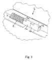
- Figure 3 shows the essential parts of the hinge mechanism 2 according to the invention as applied to the joint structure of the casings.
- the hinge pins 10a and 10b are applied to the hinge opening 7 as forced by the spring 6.
- the figure shows the open position, in which the slots and ridges in the opposite end surfaces of the hinge pins are matching.
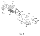
- Figure 4 shows the casings 1a and 1b of the device 1 and the hinge lugs 8a and 8b that are fastened to them as immobile.
- Axial slots 9a and 9b have been formed on the inner surface of the hinge lugs, in the position of the figure on the upper surface thereof, for form-locking the hinge pins to them so that the pins can move in relation to the lugs in the axial direction, but are immobile in relation to them in the direction of rotation.
- the hinge pins 10a and 10b are identical. Slots 11a and 11b are formed on one end surface thereof, and ridges 12a and 12b on the other end surface, see also Figure 5.
- the ridges 12a are trapezoidal pieces and are located in the edge zone of the end surface of the hinge pin.
- the outer side I of the trapezoid forms an extension of the envelope surface of the pin 10a; the opposite wall II is mainly parallel with the previous; the side wall III between them, which as seen from the front and clockwise is the side wall that moves ahead, is rectangular towards the end wall of the pin and the opposite side wall IV is inclined towards the end wall of the pin;
- the upper wall V is rectangular and parallel with the end wall.
- the slots 11a on the second end wall are of corresponding shape.
- the outer wall of the hinge pin has an axial protruding part 13a, 13b, which has a similar cross-section as the slot 9a of the hinge lug.
- the opening and closing of the device 1 shown in the figures takes place as follows, see also Figures 3 and 4.
- the hinge lugs 8a and 8b are fastened as immobile to the casings 1a and 1b.
- the location of the slot 9a, 9b in the inner wall is precisely determined in advance, because the open position or the opening angle of the device is determined by the positions of the slots 9a and 9b in relation to one another.
- the spring 6 is fitted in the hinge lug 8a, in the hinge opening 7, and the hinge pin 10a is slipped into the lug after the spring so that the protruding part 13a of the pin is in the slot 9a of the lug.
- the hinge pin 10b is slipped into the hinge lug 8b, the protruding part 13b in the slot 9b of the lug.
- the hinge lugs 8a and 8b are adjacent according to the Figure 1.
- An ordinary hinge pin, forced by the spring 14, Figure 2 operates on the other side of the hinge pin 10b.
- the adjacent end surfaces of the hinge pins 10a and 10b with their slots lla and ridges 12b are in contact with one another as forced by the springs 6 and 14.
- the position of the casings 1a and 1b shown in Figure 4 is the open position of the device, in which the opening angle is predetermined and over 90°.
- the angle position of the hinge pins 10a and 10b is the same, that is, the slots 11a and the ridges 12b are matching.
- the same situation is shown as solid view in Figure 3.
- the part 1a in order to increase the opening angle, the part 1a should turn clockwise in relation to the part 1b, or the common pushing contact surfaces III of the hinge pin 10a and the hinge pin 10b should detach the slots and ridges from one another against the effective spring force. Because the surfaces III are at a 90° angle towards the end surface, such a force in the direction of the axis of the hinge pin is not generated as to detach the slots and ridges from one another and thus to allow the hinge pins to rotate in relation to one another towards a wider opening angle.
- the part 1a in order to fold the device, the part 1a must rotate counter-clockwise, whereby the sides IV operate as the common, pushing contact surfaces. Together with the end level these surfaces form an angle which is smaller than 90°, whereby pushing one part 1a towards the other 1b generates a force in the direction of the axis of the hinge pin, which force pushes the slots and ridges away from one another, and enables the winding of the hinge pins and the hinge lugs into one another.
- the angle between the sides IV and the end level determines the strength of the force that is required to close the device; the smaller the angle the smaller the force required.
- the angle is between 80° and 40°, preferably between 70° and 60°. It appears from the above that the size of the angle is not critical, but it must be smaller than 90°.
- the hinge pins are preferably of the same shape also with regard to the length and the form and location of the protruding part 13a, 13b. This is an advantage with regard to manufacturing techniques.
- the end surfaces of the hinge pins preferably have two slots and ridges, which are diagonally opposite. However, the hinge mechanism also operates with only one slot and ridge or with two non-diagonal slots and ridges.
- the hinge pins are preferably manufactured by injection moulding from thermoplast, such as Nylon or POM. They can also be manufactured from a zinc die-cast alloy.
- the size of the opening angle is adjusted by the location of the slots 9a, 9b of the hinge lugs 8a, 8b in relation to one another.
- Figure 4 shows the position of the slots when the opening angle is over 90°. If the opening angle is to be increased, the slot 9a must be moved counter-clockwise on the surface of the hinge lug 8a, or the slot 9b must be moved clockwise on the surface of the hinge lug 8b.
Abstract
Description
- The invention relates to a hinge mechanism according to the preamble of
Claim 1. - A hinge mechanism like this is used particularly in mobile phones and different electronic manual devices. For the operation of the devices, the two parts of the device must be turned to the open position, in which position the parts are at a predetermined angle towards one another. The device stays in the open position by means of the slots and ridges of the hinge. It is desirable that the device is stable in the open position when it is used and does not close too easily. In order to close the device, a force is to be exerted on the folding part, and the exerted force must be stronger than the spring force of the hinge. With regard to ease of operation of the device, the force should be neither too strong nor too weak.
- A hinge mechanism is known from the patent specification EP-535 912, in which the force required to open and to close the device is adjusted at different strengths depending on whether the device is being opened or closed. When the device is opened, it is settled at a certain predetermined angle in which the slots and ridges of the hinge mechanism meet one another. From this position, the device can be opened to a larger angle and folded to a closed position. A stronger force is needed to open the device further than to close it. The strength of the force needed is adjusted by means of the shape of the slots and ridges formed in the hinge lug and the locking piece that is in contact with it by means of a spring. The angles of the inclined sides of the slot and ridge, which have a trapezoidal cross-section, are applied such that in the direction of rotation of the folding movement the pulling angle is wider than in the direction of rotation of the opening movement. Thus a stronger force is required to overcome the spring force to open the device further than to close it. The relative strength of the forces needed is adjusted by means of the angles. In this known construction, the opening angle can be widened by using more force. However, this implies an obvious risk that extra force exerted on the device on purpose or by accident may result in excessive opening and breaking of the device.
- The object of this invention is to achieve a hinge mechanism which is locked to a predetermined opening angle and cannot be opened beyond that point. Another object of the invention is to achieve a hinge mechanism the rigidity of which can be adjusted by simple measures.
- The above objects have been implemented by a hinge mechanism according to the invention, which is mainly characterized in that the hinge pin is divided into two parts, the first of which is form-locked in axial transition to the first hinge lug, and the second is form-locked in axial transition to the second hinge lug, that one of the end surfaces of each hinge pin has slots and the other end surface has ridges of similar shape, that the slots and ridges in the opposite end surfaces of the hinge pins forced into contact to one another by the spring are intended to fit to one another at the predetermined opening angle, and that the common contact surface of the slot and the ridge settled within it, which in the direction of rotation of the opening movement of the hinge mechanism is the side that comes behind and operates as the pushing side, is essentially perpendicular towards the end surface of the hinge pin in order to stop the opening movement, while the opposite common contact surface forms an angle smaller than 90° with the end surface of the hinge pin.
- With this construction, the opening movement of the device stops at a predetermined opening angle, and the opening angle cannot be widened further. In the open position, the two parts of the foldable device are prevented from moving outward in relation to one another. The folding of the parts takes place with a relatively weak force which is determined in advance. This ensures easy and safe operation of the device.
- In the following, the preferred embodiment of the invention will be described in more detail with reference to the appended drawings, in which
- Figure 1
- shows the foldable device with its hinge mechanism as a perspective drawing,
- Figure 2
- shows the same as Figure 1 but the hinge mechanism opened, without the hinge lugs,
- Figure 3
- shows an enlargement of the two hinge pins of the hinge mechanism and the spring forcing them as a perspective drawing,
- Figure 4
- shows an enlarged, exploded view of the mechanism according to the invention with its hinge lugs, springs and hinge pins, and
- Figure 5
- shows an enlargement of the hinge pin as a perspective drawing.
- Figure 1 shows a foldable
electronic device 1, which has twocasings 1a and 1b. The hinging of the device is shown as a complete, closed construction. - In Figure 2 the hinge mechanism is shown as revealed without the hinge lugs and barrels. As seen from the front, the
left hinge mechanism 2 is a mechanism according to the invention. Theright hinge mechanism 3 is of conventional construction, and it is not described in more detail. - Figure 3 shows the essential parts of the
hinge mechanism 2 according to the invention as applied to the joint structure of the casings. Thehinge pins spring 6. The figure shows the open position, in which the slots and ridges in the opposite end surfaces of the hinge pins are matching. - Figure 4 shows the
casings 1a and 1b of thedevice 1 and thehinge lugs - The
hinge pins Slots ridges 12a and 12b on the other end surface, see also Figure 5. Theridges 12a are trapezoidal pieces and are located in the edge zone of the end surface of the hinge pin. The outer side I of the trapezoid forms an extension of the envelope surface of thepin 10a; the opposite wall II is mainly parallel with the previous; the side wall III between them, which as seen from the front and clockwise is the side wall that moves ahead, is rectangular towards the end wall of the pin and the opposite side wall IV is inclined towards the end wall of the pin; the upper wall V is rectangular and parallel with the end wall. When the device is opened and closed, the upper walls V of theridge 12a run along the end wall of the adjacent hinge pin, until they in the open position hit theslots 11a in the end wall. - The
slots 11a on the second end wall are of corresponding shape. The outer wall of the hinge pin has an axial protrudingpart 13a, 13b, which has a similar cross-section as the slot 9a of the hinge lug. - The opening and closing of the
device 1 shown in the figures takes place as follows, see also Figures 3 and 4. Thehinge lugs casings 1a and 1b. The location of the slot 9a, 9b in the inner wall is precisely determined in advance, because the open position or the opening angle of the device is determined by the positions of the slots 9a and 9b in relation to one another. Thespring 6 is fitted in thehinge lug 8a, in the hinge opening 7, and thehinge pin 10a is slipped into the lug after the spring so that theprotruding part 13a of the pin is in the slot 9a of the lug. Thehinge pin 10b is slipped into thehinge lug 8b, the protruding part 13b in the slot 9b of the lug. Thehinge lugs spring 14, Figure 2, operates on the other side of thehinge pin 10b. The adjacent end surfaces of thehinge pins springs - The position of the
casings 1a and 1b shown in Figure 4 is the open position of the device, in which the opening angle is predetermined and over 90°. The angle position of thehinge pins slots 11a and the ridges 12b are matching. The same situation is shown as solid view in Figure 3. - The fact that the opening angle cannot be increased from this even by exerting more force becomes clear from the following: in order to increase the opening angle, the
part 1a should turn clockwise in relation to the part 1b, or the common pushing contact surfaces III of thehinge pin 10a and thehinge pin 10b should detach the slots and ridges from one another against the effective spring force. Because the surfaces III are at a 90° angle towards the end surface, such a force in the direction of the axis of the hinge pin is not generated as to detach the slots and ridges from one another and thus to allow the hinge pins to rotate in relation to one another towards a wider opening angle. - in order to fold the device, the
part 1a must rotate counter-clockwise, whereby the sides IV operate as the common, pushing contact surfaces. Together with the end level these surfaces form an angle which is smaller than 90°, whereby pushing onepart 1a towards the other 1b generates a force in the direction of the axis of the hinge pin, which force pushes the slots and ridges away from one another, and enables the winding of the hinge pins and the hinge lugs into one another. - The angle between the sides IV and the end level determines the strength of the force that is required to close the device; the smaller the angle the smaller the force required. In practice, the angle is between 80° and 40°, preferably between 70° and 60°. It appears from the above that the size of the angle is not critical, but it must be smaller than 90°.
- The hinge pins are preferably of the same shape also with regard to the length and the form and location of the
protruding part 13a, 13b. This is an advantage with regard to manufacturing techniques. The end surfaces of the hinge pins preferably have two slots and ridges, which are diagonally opposite. However, the hinge mechanism also operates with only one slot and ridge or with two non-diagonal slots and ridges. - The hinge pins are preferably manufactured by injection moulding from thermoplast, such as Nylon or POM. They can also be manufactured from a zinc die-cast alloy.
- The size of the opening angle is adjusted by the location of the slots 9a, 9b of the hinge lugs 8a, 8b in relation to one another. Figure 4 shows the position of the slots when the opening angle is over 90°. If the opening angle is to be increased, the slot 9a must be moved counter-clockwise on the surface of the
hinge lug 8a, or the slot 9b must be moved clockwise on the surface of thehinge lug 8b. - It is a considerable advantage of the hinge mechanism according to the invention that in order to implement the adjusting measures, there is no need to change the shape of the
casings 1a and 1b and their casting moulds, but the changes can be implemented by means of the shape of the hinge pins, which is much more economical in the light of manufacturing techniques.
Claims (10)
- A hinge mechanism (2) for fastening two different parts (1a, 1b) of a foldable device (1) to one another so as to enable the opening and closing of the device, which mechanism comprises a first hinge lug (8a) fastened as immobile to the first part of the device (1a) and a second hinge lug (8b) fastened as immobile to the second part of the device (1b), which hinge lugs are applied so as to settle coaxially in succession, and within which hinge lugs there is a hinge pin (10a, 10b) and a spring (6) that forces the hinge pin, characterized in that the hinge pin is divided into two parts (10a, 10b), the first (10a) of which is form-locked in axial transition to the first hinge lug (8a) and the second hinge pin part (10b) is form-locked in axial transition to the second hinge lug (8b), that there are slots (11a, 11b) in one of the end surfaces of each hinge lug, and ridges (12a, 12b) of similar shape on the second end surface, that the slots and ridges in the opposite end surfaces of the hinge pins (10a, 10b) forced into contact with one another by the spring (6) are intended to fit into one another at a certain predetermined opening angle of the device, and that the common contact surface (III) of the slot (11a, 11b) and the ridge (12a, 12b) settled within it, which in the direction of rotation of the opening movement of the hinge mechanism (2) is the side behind and operates as the pushing side, is essentially rectangular against the end surface of the hinge pin in order to stop the opening movement of the device, while the opposite common contact surface (IV) forms an angle smaller than 90° with the end surface of the hinge pin.
- A hinge mechanism according to Claim 1, characterized in that the angle between said second contact surface (IV) and the end surface of the hinge pin (10a, 10b) is between 80° and 40°, preferably between 70° and 60°.
- A hinge mechanism according to Claim 1 or 2, characterized in that the first hinge pin (10a) and the second hinge pin (10b) are of similar shape.
- A hinge mechanism according to any one of the preceding Claims 1 to 3, characterized in that the form locking of the hinge pins (10a, 10b) to the hinge lug (8a, 8b) is implemented by an axial slot (9a, 9b) formed on the inner surface of the hinge lug and by an extruding portion (13a, 13b) of corresponding shape on the outer surface of the hinge pin.
- A hinge mechanism according to any one of the preceding Claims 1 to 4, characterized in that the ridges (12a, 12b) on the end surface of the hinge pin (10a, 10b) are formed by two similar trapezoids, one vertical side (I) of which forms an extension of the envelope surface of the hinge pin, and the side (III) of the sides (II, IV) at an angle towards it, which is the side behind or the pushing side in the direction of rotation of the opening movement of the hinge mechanism, is essentially rectangular towards the end surface of the hinge pin.
- A hinge mechanism according to Claim 5, characterized in that the two trapezoids (12a, 12b) on the end surface of the hinge pin and the corresponding two trapezoidal slots (11a, 11b) on the other end surface are located diagonally opposite to one another.
- A hinge mechanism according to any one of the preceding Claims 1 to 6, characterized in that the opening angle of the device is adjusted by changing the angle position of the axial slot (9a, 9b) in the hinge lug (8a, 8b) in relation to the part of the device to which it is fastened, in order to change the mutual position of the axial slots in the second hinge lug (8a, 8b).
- A hinge mechanism according to any one of the preceding Claims 1 to 7, characterized in that the hinge pin (10a, 10b) is manufactured by injection moulding.
- A hinge mechanism according to Claim 8, characterized in that the hinge pin (10a, 10b) is manufactured from thermoplast.
- A foldable device, such as a mobile phone, characterized in that one of its hinges is a hinge mechanism (2) according to any one of the preceding claims 1 to 9, and the other hinge is an ordinary combination of hinge lugs - hinge pin (3) forced into contact with said other mechanism by a spring.
Applications Claiming Priority (2)
| Application Number | Priority Date | Filing Date | Title |
|---|---|---|---|
| FI961587A FI961587A (en) | 1996-04-11 | 1996-04-11 | Hinge mechanism for pivotally attaching two parts of a collapsible device |
| FI961587 | 1996-04-11 |
Publications (2)
| Publication Number | Publication Date |
|---|---|
| EP0801489A2 true EP0801489A2 (en) | 1997-10-15 |
| EP0801489A3 EP0801489A3 (en) | 1998-02-04 |
Family
ID=8545825
Family Applications (1)
| Application Number | Title | Priority Date | Filing Date |
|---|---|---|---|
| EP97660034A Withdrawn EP0801489A3 (en) | 1996-04-11 | 1997-03-21 | Hinge mechanism for fastening the two parts of a foldable apparatus to one another |
Country Status (3)
| Country | Link |
|---|---|
| US (1) | US5915440A (en) |
| EP (1) | EP0801489A3 (en) |
| FI (1) | FI961587A (en) |
Cited By (6)
| Publication number | Priority date | Publication date | Assignee | Title |
|---|---|---|---|---|
| EP0927923A1 (en) * | 1998-01-05 | 1999-07-07 | Siemens Aktiengesellschaft | Hinge for a computer with telecommunication device and comprising a system unit, a keyboard unit, and a display unit |
| EP1005262A2 (en) * | 1998-11-26 | 2000-05-31 | Nokia Mobile Phones Ltd. | A hinged electronic device |
| US6148079A (en) * | 1998-03-19 | 2000-11-14 | Qualcomm Incorporated | Hinge apparatus for flip style portable phone |
| US6157717A (en) * | 1998-03-19 | 2000-12-05 | Qualcomm Incorporated | Snap hinge mechanism for flip style portable phone |
| US6460221B1 (en) | 1999-11-30 | 2002-10-08 | Nokia Mobile Phones Ltd. | Hinged electronic device |
| US6807712B2 (en) | 2000-06-29 | 2004-10-26 | Nokia Mobile Phones Ltd. | Hinge having engagement surface to restrain rotational movement and electronic device containing such a hinge |
Families Citing this family (14)
| Publication number | Priority date | Publication date | Assignee | Title |
|---|---|---|---|---|
| FR2762557B1 (en) * | 1997-04-25 | 1999-07-16 | Itw De France | ARTICLE COMPRISING TWO ELEMENTS ARTICULATED ONE IN RELATION TO THE OTHER |
| SE511799C2 (en) * | 1998-03-24 | 1999-11-29 | Ericsson Telefon Ab L M | Hinge device at a mobile phone device with a door |
| JP3489668B2 (en) * | 1999-05-31 | 2004-01-26 | スガツネ工業株式会社 | Hinge device for holding open / close of foldable equipment |
| US6377444B1 (en) * | 1999-11-30 | 2002-04-23 | Ingersoll-Rand Company | Hinged housings for electronic devices |
| US6678539B1 (en) * | 2001-01-22 | 2004-01-13 | Lu Sheng-Nan | Mobile phone cover hinge |
| US6968056B2 (en) * | 2001-12-21 | 2005-11-22 | Nokia Corporation | Mobile phone with elastic hinge |
| JP2003329029A (en) * | 2002-05-15 | 2003-11-19 | Fujitsu Ltd | Hinge structure and display unit |
| US6820307B2 (en) * | 2002-09-17 | 2004-11-23 | Shin Zu Shing Co., Ltd. | Elastic hinge for a notebook computer |
| JP2004346992A (en) * | 2003-05-21 | 2004-12-09 | Matsushita Electric Ind Co Ltd | Opening and closing device |
| US20050091431A1 (en) * | 2003-10-23 | 2005-04-28 | Robert Olodort | Portable communication devices |
| CN101541153B (en) * | 2008-03-19 | 2011-12-07 | 深圳富泰宏精密工业有限公司 | Rotating shaft structure of portable type electronic device and method assembling same |
| US20110073723A1 (en) * | 2009-09-25 | 2011-03-31 | Ashpole Benjamin C | Joint and foldable structures employing the same |
| CN102235417A (en) * | 2010-04-20 | 2011-11-09 | 鸿富锦精密工业(深圳)有限公司 | Hinge and electronic device with hinges |
| US9851797B1 (en) | 2016-08-18 | 2017-12-26 | Microsoft Technology Licensing, Llc | Haptic arrangement of a multiple part electronic device |
Citations (3)
| Publication number | Priority date | Publication date | Assignee | Title |
|---|---|---|---|---|
| FR364243A (en) * | 1906-03-14 | 1906-08-17 | Laurent Jacquet | Automatic and safety hinge for unlimited closing and opening of doors and windows |
| EP0422882A1 (en) * | 1989-10-11 | 1991-04-17 | Sugatsune Industrial Co., Ltd. | Door hinge |
| EP0535912A2 (en) * | 1991-09-30 | 1993-04-07 | Nec Corporation | Hinge mechanism for foldable electronic apparatus |
Family Cites Families (13)
| Publication number | Priority date | Publication date | Assignee | Title |
|---|---|---|---|---|
| US2362923A (en) * | 1941-12-09 | 1944-11-14 | Norman H Pardoe | Ratchet hinge for vehicle doors |
| FI83276C (en) * | 1989-02-03 | 1991-06-10 | Nokia Mobira Oy | Mounting system for car phone devices |
| FI83277C (en) * | 1989-02-03 | 1991-06-10 | Nokia Mobira Oy | Stand for handset |
| FI81229C (en) * | 1989-02-03 | 1990-09-10 | Nokia Mobira Oy | Fastening system of holder for radio telephone control device |
| US4957264A (en) * | 1989-02-08 | 1990-09-18 | Nokia-Mobira Oy | Mounting base for a telephone device, such as a mobile telephone |
| FI85549C (en) * | 1990-04-12 | 1992-04-27 | Nokia Mobile Phones Ltd | HAOLLARE FOER TELEFON ELLER MANOEVRERINGSANORDNING. |
| FI85072C (en) * | 1990-04-12 | 1992-02-25 | Nokia Mobile Phones Ltd | Circuit arrangement. |
| US5274882A (en) * | 1992-03-03 | 1994-01-04 | Ericsson Ge Mobile Communications Inc. | Hinge mechanism |
| US5398378A (en) * | 1993-07-02 | 1995-03-21 | Lin; Chi-Chung | Hinge having an automatic recovery mechanism |
| KR0118819Y1 (en) * | 1993-11-30 | 1998-07-15 | 김광호 | Door opering device in ref |
| FI96553B (en) * | 1994-05-18 | 1996-03-29 | Nokia Mobile Phones Ltd | Mobile device mounting device |
| KR200141099Y1 (en) * | 1995-09-19 | 1999-05-15 | 김광호 | Button cover of a portable telephone |
| US5715576A (en) * | 1997-02-04 | 1998-02-10 | Liu; Tai-Sheng | Hinge device for coupling two rotatable members |
-
1996
- 1996-04-11 FI FI961587A patent/FI961587A/en unknown
-
1997
- 1997-03-21 EP EP97660034A patent/EP0801489A3/en not_active Withdrawn
- 1997-04-09 US US08/833,713 patent/US5915440A/en not_active Expired - Lifetime
Patent Citations (3)
| Publication number | Priority date | Publication date | Assignee | Title |
|---|---|---|---|---|
| FR364243A (en) * | 1906-03-14 | 1906-08-17 | Laurent Jacquet | Automatic and safety hinge for unlimited closing and opening of doors and windows |
| EP0422882A1 (en) * | 1989-10-11 | 1991-04-17 | Sugatsune Industrial Co., Ltd. | Door hinge |
| EP0535912A2 (en) * | 1991-09-30 | 1993-04-07 | Nec Corporation | Hinge mechanism for foldable electronic apparatus |
Cited By (8)
| Publication number | Priority date | Publication date | Assignee | Title |
|---|---|---|---|---|
| EP0927923A1 (en) * | 1998-01-05 | 1999-07-07 | Siemens Aktiengesellschaft | Hinge for a computer with telecommunication device and comprising a system unit, a keyboard unit, and a display unit |
| US6148079A (en) * | 1998-03-19 | 2000-11-14 | Qualcomm Incorporated | Hinge apparatus for flip style portable phone |
| US6157717A (en) * | 1998-03-19 | 2000-12-05 | Qualcomm Incorporated | Snap hinge mechanism for flip style portable phone |
| EP1005262A2 (en) * | 1998-11-26 | 2000-05-31 | Nokia Mobile Phones Ltd. | A hinged electronic device |
| EP1005262A3 (en) * | 1998-11-26 | 2000-12-27 | Nokia Mobile Phones Ltd. | A hinged electronic device |
| US6308377B1 (en) | 1998-11-26 | 2001-10-30 | Nokia Mobile Phones Ltd. | Hinged electronic device |
| US6460221B1 (en) | 1999-11-30 | 2002-10-08 | Nokia Mobile Phones Ltd. | Hinged electronic device |
| US6807712B2 (en) | 2000-06-29 | 2004-10-26 | Nokia Mobile Phones Ltd. | Hinge having engagement surface to restrain rotational movement and electronic device containing such a hinge |
Also Published As
| Publication number | Publication date |
|---|---|
| FI961587A (en) | 1997-10-12 |
| EP0801489A3 (en) | 1998-02-04 |
| US5915440A (en) | 1999-06-29 |
| FI961587A0 (en) | 1996-04-11 |
Similar Documents
| Publication | Publication Date | Title |
|---|---|---|
| EP0801489A2 (en) | Hinge mechanism for fastening the two parts of a foldable apparatus to one another | |
| EP1612355B1 (en) | Disappearing hinging device for windows and doors with wing and swivel wing opening | |
| EP0787881A1 (en) | Overhead doors and panels therefore | |
| EP1363091A3 (en) | Door opening/closing mechanism and manufacturing method thereof | |
| EP0807740A3 (en) | Double swing door opening/closing mechanism | |
| US7591044B2 (en) | Hinge for furniture with a low thickness and improved structure | |
| DE102006036503B4 (en) | Combined mechanical and electronic key | |
| EP0950588B1 (en) | Cover for a headlamp cleaning device | |
| DE3137552A1 (en) | "SNAP HINGE" | |
| NZ224244A (en) | Window stay | |
| US5457913A (en) | Hinge mounting for auto ventilation window | |
| EP0495233B1 (en) | Check for a window, door or the like | |
| GB2215775A (en) | Hinges | |
| EP1199428B1 (en) | Espagnolette locking device | |
| US5475897A (en) | Car door hinge | |
| DE19600553C1 (en) | Cover for gate hinge, especially for sectional gate hinges | |
| EP0428196A1 (en) | Revolving door | |
| EP1728948B1 (en) | Striker plate for a lock of an espagnolette fitting and lock for an espagnolet fitting | |
| US20070000087A1 (en) | Door hinge | |
| DE19649311C1 (en) | Stop element especially for tailgate of motor vehicles | |
| DE19651692A1 (en) | Rear flap connection for motor vehicle | |
| CN218029675U (en) | Multi-connecting-rod hinge | |
| JP2589363Y2 (en) | Hinge | |
| GB2155540A (en) | Hinge with integral check | |
| EP1681415A1 (en) | Friction stay |
Legal Events
| Date | Code | Title | Description |
|---|---|---|---|
| PUAI | Public reference made under article 153(3) epc to a published international application that has entered the european phase |
Free format text: ORIGINAL CODE: 0009012 |
|
| AK | Designated contracting states |
Kind code of ref document: A2 Designated state(s): DE FR GB SE |
|
| PUAL | Search report despatched |
Free format text: ORIGINAL CODE: 0009013 |
|
| AK | Designated contracting states |
Kind code of ref document: A3 Designated state(s): DE FR GB SE |
|
| 17P | Request for examination filed |
Effective date: 19980210 |
|
| RAP1 | Party data changed (applicant data changed or rights of an application transferred) |
Owner name: NOKIA CORPORATION |
|
| STAA | Information on the status of an ep patent application or granted ep patent |
Free format text: STATUS: THE APPLICATION HAS BEEN WITHDRAWN |
|
| 18W | Application withdrawn |
Withdrawal date: 20021029 |