EP0801442A1 - Connector connecting structure - Google Patents
Connector connecting structure Download PDFInfo
- Publication number
- EP0801442A1 EP0801442A1 EP97105775A EP97105775A EP0801442A1 EP 0801442 A1 EP0801442 A1 EP 0801442A1 EP 97105775 A EP97105775 A EP 97105775A EP 97105775 A EP97105775 A EP 97105775A EP 0801442 A1 EP0801442 A1 EP 0801442A1
- Authority
- EP
- European Patent Office
- Prior art keywords
- connector
- holder
- portions
- connectors
- swingable
- Prior art date
- Legal status (The legal status is an assumption and is not a legal conclusion. Google has not performed a legal analysis and makes no representation as to the accuracy of the status listed.)
- Granted
Links
- 230000002265 prevention Effects 0.000 claims description 35
- 238000006073 displacement reaction Methods 0.000 abstract description 12
- 238000009434 installation Methods 0.000 description 23
- 238000003780 insertion Methods 0.000 description 5
- 230000037431 insertion Effects 0.000 description 5
- 238000004378 air conditioning Methods 0.000 description 4
- 238000004519 manufacturing process Methods 0.000 description 2
- 238000000034 method Methods 0.000 description 2
- 238000005476 soldering Methods 0.000 description 2
- 230000015572 biosynthetic process Effects 0.000 description 1
Images




Classifications
-
- H—ELECTRICITY
- H01—ELECTRIC ELEMENTS
- H01R—ELECTRICALLY-CONDUCTIVE CONNECTIONS; STRUCTURAL ASSOCIATIONS OF A PLURALITY OF MUTUALLY-INSULATED ELECTRICAL CONNECTING ELEMENTS; COUPLING DEVICES; CURRENT COLLECTORS
- H01R13/00—Details of coupling devices of the kinds covered by groups H01R12/70 or H01R24/00 - H01R33/00
- H01R13/62—Means for facilitating engagement or disengagement of coupling parts or for holding them in engagement
- H01R13/629—Additional means for facilitating engagement or disengagement of coupling parts, e.g. aligning or guiding means, levers, gas pressure electrical locking indicators, manufacturing tolerances
- H01R13/62905—Additional means for facilitating engagement or disengagement of coupling parts, e.g. aligning or guiding means, levers, gas pressure electrical locking indicators, manufacturing tolerances comprising a camming member
- H01R13/62922—Pair of camming plates
-
- H—ELECTRICITY
- H01—ELECTRIC ELEMENTS
- H01R—ELECTRICALLY-CONDUCTIVE CONNECTIONS; STRUCTURAL ASSOCIATIONS OF A PLURALITY OF MUTUALLY-INSULATED ELECTRICAL CONNECTING ELEMENTS; COUPLING DEVICES; CURRENT COLLECTORS
- H01R13/00—Details of coupling devices of the kinds covered by groups H01R12/70 or H01R24/00 - H01R33/00
- H01R13/62—Means for facilitating engagement or disengagement of coupling parts or for holding them in engagement
- H01R13/629—Additional means for facilitating engagement or disengagement of coupling parts, e.g. aligning or guiding means, levers, gas pressure electrical locking indicators, manufacturing tolerances
- H01R13/62933—Comprising exclusively pivoting lever
- H01R13/62966—Comprising two pivoting levers
- H01R13/62972—Wherein the pivoting levers are two lever plates
-
- H—ELECTRICITY
- H01—ELECTRIC ELEMENTS
- H01R—ELECTRICALLY-CONDUCTIVE CONNECTIONS; STRUCTURAL ASSOCIATIONS OF A PLURALITY OF MUTUALLY-INSULATED ELECTRICAL CONNECTING ELEMENTS; COUPLING DEVICES; CURRENT COLLECTORS
- H01R12/00—Structural associations of a plurality of mutually-insulated electrical connecting elements, specially adapted for printed circuits, e.g. printed circuit boards [PCB], flat or ribbon cables, or like generally planar structures, e.g. terminal strips, terminal blocks; Coupling devices specially adapted for printed circuits, flat or ribbon cables, or like generally planar structures; Terminals specially adapted for contact with, or insertion into, printed circuits, flat or ribbon cables, or like generally planar structures
- H01R12/70—Coupling devices
- H01R12/7005—Guiding, mounting, polarizing or locking means; Extractors
- H01R12/7011—Locking or fixing a connector to a PCB
- H01R12/7064—Press fitting
-
- H—ELECTRICITY
- H01—ELECTRIC ELEMENTS
- H01R—ELECTRICALLY-CONDUCTIVE CONNECTIONS; STRUCTURAL ASSOCIATIONS OF A PLURALITY OF MUTUALLY-INSULATED ELECTRICAL CONNECTING ELEMENTS; COUPLING DEVICES; CURRENT COLLECTORS
- H01R12/00—Structural associations of a plurality of mutually-insulated electrical connecting elements, specially adapted for printed circuits, e.g. printed circuit boards [PCB], flat or ribbon cables, or like generally planar structures, e.g. terminal strips, terminal blocks; Coupling devices specially adapted for printed circuits, flat or ribbon cables, or like generally planar structures; Terminals specially adapted for contact with, or insertion into, printed circuits, flat or ribbon cables, or like generally planar structures
- H01R12/70—Coupling devices
- H01R12/7005—Guiding, mounting, polarizing or locking means; Extractors
- H01R12/7011—Locking or fixing a connector to a PCB
- H01R12/707—Soldering or welding
-
- H—ELECTRICITY
- H01—ELECTRIC ELEMENTS
- H01R—ELECTRICALLY-CONDUCTIVE CONNECTIONS; STRUCTURAL ASSOCIATIONS OF A PLURALITY OF MUTUALLY-INSULATED ELECTRICAL CONNECTING ELEMENTS; COUPLING DEVICES; CURRENT COLLECTORS
- H01R12/00—Structural associations of a plurality of mutually-insulated electrical connecting elements, specially adapted for printed circuits, e.g. printed circuit boards [PCB], flat or ribbon cables, or like generally planar structures, e.g. terminal strips, terminal blocks; Coupling devices specially adapted for printed circuits, flat or ribbon cables, or like generally planar structures; Terminals specially adapted for contact with, or insertion into, printed circuits, flat or ribbon cables, or like generally planar structures
- H01R12/70—Coupling devices
- H01R12/71—Coupling devices for rigid printing circuits or like structures
- H01R12/72—Coupling devices for rigid printing circuits or like structures coupling with the edge of the rigid printed circuits or like structures
- H01R12/722—Coupling devices for rigid printing circuits or like structures coupling with the edge of the rigid printed circuits or like structures coupling devices mounted on the edge of the printed circuits
- H01R12/724—Coupling devices for rigid printing circuits or like structures coupling with the edge of the rigid printed circuits or like structures coupling devices mounted on the edge of the printed circuits containing contact members forming a right angle
-
- H—ELECTRICITY
- H01—ELECTRIC ELEMENTS
- H01R—ELECTRICALLY-CONDUCTIVE CONNECTIONS; STRUCTURAL ASSOCIATIONS OF A PLURALITY OF MUTUALLY-INSULATED ELECTRICAL CONNECTING ELEMENTS; COUPLING DEVICES; CURRENT COLLECTORS
- H01R13/00—Details of coupling devices of the kinds covered by groups H01R12/70 or H01R24/00 - H01R33/00
- H01R13/62—Means for facilitating engagement or disengagement of coupling parts or for holding them in engagement
- H01R13/629—Additional means for facilitating engagement or disengagement of coupling parts, e.g. aligning or guiding means, levers, gas pressure electrical locking indicators, manufacturing tolerances
- H01R13/62933—Comprising exclusively pivoting lever
- H01R13/62938—Pivoting lever comprising own camming means
-
- H—ELECTRICITY
- H01—ELECTRIC ELEMENTS
- H01R—ELECTRICALLY-CONDUCTIVE CONNECTIONS; STRUCTURAL ASSOCIATIONS OF A PLURALITY OF MUTUALLY-INSULATED ELECTRICAL CONNECTING ELEMENTS; COUPLING DEVICES; CURRENT COLLECTORS
- H01R13/00—Details of coupling devices of the kinds covered by groups H01R12/70 or H01R24/00 - H01R33/00
- H01R13/62—Means for facilitating engagement or disengagement of coupling parts or for holding them in engagement
- H01R13/629—Additional means for facilitating engagement or disengagement of coupling parts, e.g. aligning or guiding means, levers, gas pressure electrical locking indicators, manufacturing tolerances
- H01R13/62933—Comprising exclusively pivoting lever
- H01R13/62944—Pivoting lever comprising gear teeth
-
- H—ELECTRICITY
- H01—ELECTRIC ELEMENTS
- H01R—ELECTRICALLY-CONDUCTIVE CONNECTIONS; STRUCTURAL ASSOCIATIONS OF A PLURALITY OF MUTUALLY-INSULATED ELECTRICAL CONNECTING ELEMENTS; COUPLING DEVICES; CURRENT COLLECTORS
- H01R13/00—Details of coupling devices of the kinds covered by groups H01R12/70 or H01R24/00 - H01R33/00
- H01R13/73—Means for mounting coupling parts to apparatus or structures, e.g. to a wall
- H01R13/74—Means for mounting coupling parts in openings of a panel
Definitions
- the present invention relates to a connector connecting structure which connects mutually corresponding male and female connectors to each other to thereby allow them to be in electric conduction with each other.
- the conventional electric connector includes a holder (a slide member) which is used to hold a first connector inserted therein and includes a plurality of engaging projections formed in the upper and lower wall surfaces thereof, a second connector which is formed in a substantially rectangular shape and includes not only a recessed portion into which the holder can be inserted but also an opening formed in the side wall thereof substantially in parallel to the side wall, and a substantially U-shaped operation member including a cam grooves which is engageable with the engaging projections of the holder, wherein the first and second connectors can be connected to each other by sliding the operation member.
- a holder a slide member
- the second connector engaged with the operation member is provisionally engaged with the first connector held by the holder, and the engaging projections formed in the holder are matched in position to the cam groove formed in the operation member. After then, by pushing the operation member in the longitudinal direction of the holder, the first connector must be connected to the second connector. That is, in this structure, the connecting operation must be executed at two or more stages, which is troublesome.
- the width dimension of the connector can be reduced.
- the operation member projects out laterally of the connector to a great extent, it is necessary to secure a space for operation of the operation member, which raises a problem that a large dead space is inevitably produced.
- a multi-polar connector of a low insertion force type in which, in one connector, a pinion is rotatably supported and a slide rack piece member to be engaged with the pinion is slidably supported, and, in the other connector, there is provided a fixing rack portion to be engaged with the pinion of one connector, whereby, if the slide rack piece member is operated or slid to thereby drive or rotate the pinion, then the two connectors can be connected to each other.
- the above-mentioned conventional low insertion force multi-polar connector is structured such that a male connector housing forming one connector is provisionally fitted with a female connector housing forming the other connector to thereby bring the pinion supported in the male connector housing into meshing engagement with the front portion of the fixing rack portion formed in the female connector housing and, after then, if an operator pushes in the slide rack piece member supported in the male connector housing by his or her finger to thereby cause the same to slide, then the slide rack piece member is allowed to roll on the fixing rack portion while the pinion is being rotated, thereby applying a forwardly advancing force to the pinion, so that the two connectors can be connected together.
- the present invention aims at eliminating the drawbacks found in the above-mentioned conventional connector connecting structure. Accordingly, it is an object of the invention to provide a connector connecting structure which is able to connect a pair of connectors to each other positively by a simple operation and is also able to reduce a connector installation space.
- a connector connecting structure comprising a first connector supported by a holder and a second connector to be connected to the first connector, wherein there is provided in the holder a support portion for supporting the first connector in such a manner that the first connector can be slid in the connecting direction of the first and second connectors, and a slide member slidingly displaceable in a direction at right angles to the connecting direction of the two connectors is supported between the holder and said second connector, and also wherein there are further provided a drive part for sliding and displacing the slide member according to the sliding displacement of the first connector, and an operation part for increasing the drive force of the slide member and transmitting the thus increased drive force to the connecting portions of the first and second connectors to thereby be able to drive the two connectors in the connecting direction thereof.
- the slide member is slid and displaced according to the drive force input therein from the drive part, and the drive force is increased and transmitted from the operation part to the connecting portion of the two connectors, so that a great connecting force can be applied to the two connectors.
- a plate-shaped slide member is interposed between the inner wall surface of the holder and the outer wall surface of the first connector.
- the installation space of the slide member can be controlled down to a small space, which makes it possible to reduce the size of the connector.
- a pair of slide members are respectively so provided as to extend along the mutually opposed wall surfaces of the holder, and the two slide members are arranged at point symmetrical positions to each other.
- a removal prevention portion which is used to prevent the first connector from being pulled out forwardly from the holder.
- provision of the removal prevention portion prevents the possibility that the first connector inserted into the holder can be pulled out from the holder and the connected condition between the holder and first connector can be thereby removed.
- a provisionally securing portion which is used to secure the first connector at a connection wait position provisionally, and the provisionally secured condition of the first connector by the provisionally securing portion can be removed according to the operation force for connecting the first and second connectors to each other.
- the first connector before the two connectors are connected together, the first connector can be provisionally secured at the connection wait position by the provisionally securing portion and, in the two connectors connecting operation, the provisionally secured condition of the first connector by the provisionally securing portion can be removed and thus the first connector can be slid and displaced along the holder.
- a connector connecting structure comprising a first connector supported slidably by a holder and a second connector to be connected to the first connector, wherein a swingable member including a pinion portion in the leading end portion thereof is swingably supported between the holder and first connector, there is provided in the connector a rack portion meshingly engageable with the pinion portion of the swingable member, there is provided a drive part which, in an operation to connect the second connector to-the first connector, can swing and displace the swingable member according to the sliding motion of the first connector to thereby drive the pinion portion in a direction where the second connector is moved toward the first connector, and a distance from the drive part to the swing support point of the swingable member is set larger than a distance from the pinion portion of the swingable member to the swing support point of the swingable member.
- the swingable member is driven by the drive part and is thereby swung and displaced and, at the same time, the drive force of the swingable member is increased according to the principles of leverage and the thus increased drive force is then transmitted from the pinion portion of the swingable member to the rack portion of the second connector in meshing engagement with the pinion portion of the swingable member, so that the second connector can be driven or moved toward the first connector with a great force.
- a plate-shaped swingable member is interposed between the wall surface of the holder and the wall surface of the first connector that is opposed to the present holder wall surface.
- a pair of swingable members are respectively installed along the mutually opposed wall surfaces of the holder, and the two swingable members are arranged at positions symmetrical to each other with respect to a point.
- a removal prevention portion which is used to prevent the first connector from being pulled out forwardly from the holder.
- the removal prevention portion eliminates the possibility that the first connector supported within the holder can be pulled out from the holder to thereby remove the connected condition between the holder and first connector.
- a provisionally securing portion which secures the first connector provisionally at a connection wait position, and the provisionally secured condition of the first connector by the provisionally securing portion can be removed according to an operation force for connecting the first and second connectors to each other.
- the first connector before the two connectors are connected together, the first connector is provisionally secured at the connection wait position by the provisionally securing portion and, in the connecting operation of the two connectors, the provisionally secured condition of the first connector by the provisionally securing portion can be removed automatically so that the first connector can be slid along the holder.
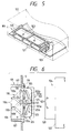
- Fig. 1 shows a first embodiment of a connector connecting structure according to the invention.
- the present connector comprises a holder 101 mounted on a mounting portion S which consists of a stay member or the like provided in a vehicle, a first connector 102 supported slidably by the holder 101, a second connector 104 mounted on a circuit board 103 which forms an electronic unit 122, and a pair of slide members 105 which are respectively used to drive the second connector 104 in a direction where the second connector 104 can be connected to the first connector 102.
- the holder 101 is formed in a tubular shape which includes a pair of top and bottom horizontal plates 106 and a pair of right and left side plates 107, while the holder 101 can be fitted into a mounting hole formed in the mounting portion S of the vehicle body and can be fixed thereto by a screw or similar fixing means. And, in the respective wall surfaces of the two right and left side plates 107 of the holder 101 , there are formed support portions which respectively extend in the horizontal direction thereof and respectively consist of a pair of upper and lower recessed grooves 108 used to support the first connector 102 in a such a manner that it can be freely slid.
- Each of the slide members 105 includes a pair of engaging pins 109 which are respectively provided on and projected from the upper surface of the rear end portion of the slide member 105.
- the horizontal plate 106 there are formed a pair of guide grooves 110 which are arranged in parallel to each other.
- the two engaging pins 109 can be engaged with the two guide grooves 110, respectively.
- Each of the guide grooves 110 includes an introduction portion 110a extending backwardly from the front end portion of the holder 101, a drive groove portion 110b backwardly and inwardly from the rear portion of the introduction portion 110a, and a securing portion 110c extending backwardly from the end portion of the drive groove portion 110b.
- the drive groove portion 110b is formed such that it extends backwardly and inwardly of the rear portion of the holder 101 in a straight line.
- the drive groove portion may also be formed such that it extends backwardly and inwardly from the end portion of the introduction portion 110a in a curved line.
- the guide groove 110 formed in the upper horizontal plate 106 is symmetrical to the guide groove 110 formed in the lower horizontal plate 106. That is, in the present embodiment, when viewed from the front surface side of the holder 101, a pair of guide grooves 110 are formed in parallel to each other on the right side of the upper horizontal plate 106, while a pair of guide grooves 110 are formed in parallel to each other on the left side of the lower horizontal plate 106.
- the horizontal plates 106 of the holder 101 include slits 112a which are respectively formed on the right and left portions of the inner wall surfaces of the horizontal plates 106 and also which respectively have a given width. Due to provision of the slits 112a, there is provided a removal prevention portion 112 which secures the first connector 102 at its forward wait position, while the removal prevention portion 112 includes in the leading end portion thereof securing stepped portions 112b which are respectively opposed to projecting portions 117 formed in the rear portion of the first connector 102.
- each of the securing stepped portions 112b includes a tapered surface on the outer surface of the leading end portion thereof, so that the securing stepped portion 112b has a forwardly tapered shape.
- the first connector 102 includes a male-type connector housing 114 which can be inserted into the holder 101 and can be supported slidably therein, and a plurality of female-type terminals which are disposed within a terminal storage chamber formed in the connector housing 114.
- the connector housing 114 includes a pair of upper and lower projecting portions 116 which are respectively formed on the right and left side surfaces of the rear end portion of the connector housing 114 in such a manner that they can be slid along the recessed grooves 108 of the holder 101.
- the connector housing 114 further includes projecting portions 117 which are provided on the right and left sides of the upper and lower surfaces of the rear end portion thereof in such a manner that they can be secured to the securing stepped portions 112b of the removal prevention portion 112.
- provisionally securing portions 118 which are used to secure the first connector 102 provisionally at the above-mentioned connection wait position to thereby prevent the first connector 102 from being pushed into the holder 101 before the execution of a connectors connecting operation to be described later.
- Each of the provisionally securing portions 118 includes a base end portion 118a projectingly provided on the side wall surface of the connector housing 114, a plate-shaped portion 118b which extends backwardly while it is opposed to the side wall surface of the connector housing 114 with a given clearance between them, and a projecting portion 118c which is projectingly provided on the outer surface of the rear portion of the plate-shaped portion 118b.
- the projecting portion 118c of the provisionally securing portion 118 when viewed from a plane thereof, is so formed as to have a triangular shape and, on the outer side surface thereof, there are formed a pair of tapered surfaces. Also, on the front surface of the holder 101, there is provided a projection 119 including a pair of tapered surfaces corresponding to the tapered surfaces of the projecting portion 118c. And, in operation, the rear tapered surface of the projecting portion 118c provided in the provisionally securing portion 118 is contacted with the front tapered surface of the projection 119 provided on the holder 101 to thereby be able to secure the first connector 102 provisionally at the connection wait position.
- the second connector 104 includes a female-type connector housing 120 which can be fitted over and engaged with the connector housing 114 of the first connector 102, and a plurality of male-type terminals 121 disposed within a terminal storage chamber formed in the connector housing 120.
- the connector housing 120 is fixed onto the circuit board 103 by screwing or by other similar fixing means, while the connecting portions 121a of the male-type terminals 121 are respectively guided out from the rear end portion of the connector housing 120 and are connected to the introduction portion of the circuit board 103 by soldering or by other similar connecting means (see Fig. 1).
- the connector housing 120 further includes on the outer surface thereof a pair of driven pins 123 which can be driven by the slide member 105, while the driven pins 123 are projectingly provided at a position opposed to the installation position of the slide member 105.
- the above-mentioned slide members 105 are respectively formed of plate members interposed between the inner wall surfaces of the holder 101, which are composed of the lower surface of the upper horizontal plate 106 and the upper surface of the lower horizontal plate 106 respectively forming the holder 101, and the outer wall surfaces of the first connector 102 which are composed of the upper and lower surfaces of the connector housing 114. Also, as shown in Figs. 2 and 6, each of the slide members 105 is slidably supported by a pair of connecting pins 111 projectingly provided on the connector housing 114 of the first connector 102 at a position which is opposed to the guide groove 110 formed in the holder 101.
- the slide member 105 there is formed a guide groove 124 which extends laterally (longitudinally) of the holder 101 and first connector 102 and, thus, if the pair of connecting pins 111 are fitted into the present guide groove 124, then the slide member 105 is supported in such a manner that not only the oscillating displacement of the slide member 105 can be restricted by the two connecting pins 111 but also the slide member 105 is allowed to be slid and displaced in a direction at right angles to the connecting direction of the two connectors 102 and 104 within the range of formation of the guide groove 124.
- the slidingly displacing direction of the slide member 105 is not always limited to the above direction that extends exactly at right angles to the connecting direction of the two connectors 102 and 104.
- Each of the two engaging grooves 125 of the slide member 105 is composed of an opening portion 125a, which serves as an introduction and guide portion for its corresponding driven pin 123, and an operation groove portion 125b which continues with the opening portion 125a and extends outwardly of the rear portion of the slide member 105.
- the operation groove portion 125b is formed such that the width direction dimension thereof is set substantially the same as the width dimension of the drive groove portion 110b of the holder 101 and the longitudinal direction dimension thereof is set for a value smaller than the value of the longitudinal direction dimension of the drive groove portion 110b of the holder 101, whereby the directions of inclination of the operation groove portion 125b and drive groove portion 110b are set such that the angle of inclination of the operation groove portion 125b with respect to the width direction of the connector is smaller than the angle of inclination of the drive groove portion 110b formed in the holder 101.
- the slide members 105 are slid and displaced (which will be discussed later) to thereby transmit a drive force from the engaging grooves 125 of the slide member 105 to the driven pins 123, so that the second connector 104 can be driven or drawn toward the first connector 102.
- the directions of inclination of the operation groove portions 125b and drive groove portions 110b are set such that the angle of inclination of the operation groove portions 125b with respect to the width direction of the connector is smaller than the angle of inclination of the drive groove portions 110b formed in the holder 101, the amount of movement of the second connector 104 in the above-mentioned connecting direction is smaller than the amount of movement of the first connector 102 when it is pushed into the holder 101 according to the connecting operation force for connecting together the two connectors 102 and 104, with the result that the drive force transmitted from the drive groove portions 110b to the slide members 105 can be increased before it is transmitted to the second connector 104.
- the drive groove portions 110b of the guide grooves 110 respectively formed in the holder 101 and the engaging pins 109 to be fitted into the drive groove portions 110b cooperate in forming a drive part which, according to the sliding displacement of the first connector 102, drives the slide members 105 so that they are slid and displaced; and, the operation groove portions 125b of the engaging grooves 125 respectively formed in the slide members 105 and the driven pins 123 to be engaged with the operation groove portions 125b cooperate in forming an operation part which increases the drive force of the slide members 105 and transmits the thus increased drive force to the connecting portions of the first and second connectors 102 and 104 to thereby drive the two connectors 102 and 104 in a direction where they can be connected.
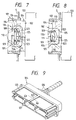
- the first connector 102 having their female-type terminals 115 assembled into the male-type connector housing 114 is disposed opposingly to the opening of the leading end portion of the holder 101 as shown by a virtual line in Fig. 3 and, after then, the connector housing 114 is pushed in a direction of an arrow shown in Fig. 3 and is inserted into the holder 101, so that the first connector 102 can be set at a connection wait position as shown by a solid line in Fig. 3.
- the projecting portions 117 of the connector housing 114 are respectively pressed against the tapered surfaces 112c of the removal prevention portions 112 provided in the horizontal plates 106 of the holder 101, so that the removal prevention portions 112 are elastically deformed. And, the projecting portions 117 are fitted into the holder 101 beyond the securing stepped portions 112b of the removal prevention portions 112 and, as shown in Fig. 4, the first connector 102 is provisionally secured at the connection wait position where the projecting portions 118c of the provisionally securing portions 118 provided on the side surfaces of the connector housing 114 are brought into contact with the front surfaces of the projections 119 respectively provided on the two side plates 107 of the holder 101.
- the engaging pins 109 provided on the rear end portions of the slide members 105 are respectively introduced into the guide grooves 110 of the holder 101 and the engaging pins 109 are respectively engaged with the rear end positions of the introduction portions 110a of the guide grooves 110.
- the connector housing 120 of the second connector 104 can be fitted over and assembled with the connector housing 114 of the first connector 120, so that the first and second connectors 102 and 104 can be connected with each other in such a manner that they are held in electric conduction.
- the projecting portions 118c of the provisionally securing portions 118 provided on the side surfaces of the second connector 104 are respectively pressed against the projections 119 of the holder 101, so that the plate-shaped portions 118b of the provisionally securing portions 118 are elastically deformed. And, after the projecting portions 118c of the provisionally securing portions 118 are moved beyond the projections 119 of the holder 101, not only the connector housing 114 of the first connector 102, as shown in Fig.
- the slide members 105 are slid backwardly and inwardly along the drive groove portions 110b of the guide grooves 110 in response to the backward sliding displacement of the first connector 102, the slide members 105 are slid and displaced toward the central portion of the first connector 102 while they are being supported by the connecting pins 111 and, in response to the sliding displacement of the slide members 105, the driven pins 123 of the second connector 104 are driven by the slide members 105 and are thereby drawn toward the first connector 102.
- the inclination angle of the drive groove portions 110b forming the drive part for driving the slide members 105 with respect to the connecting direction of the two connectors 102 and 104 is set larger than the inclination angle of the operation groove portions 125b forming the operation part for driving the second connector 104, so that, in the above-mentioned connecting operation of the first and second connectors 102 and 104, the drive force input to the slide members 105 can be increased according as the first connector 102 is slid and displaced backwardly and the thus increased drive force can be transmitted to the driven pins 123. Due to this, according to such drive force, the second connector 104 can be pushed toward the first connector 102 with a great force, so that the first and second connectors 102 and 104 can be connected together reliably.
- the first and second connectors 102, 104 and slide members 105 are integrally moved backwardly of the holder 101, even if the amount of push-in movement of the electronic unit 122 varies to some extent, the two connectors 102 and 104 can be shifted to a completely connected condition.
- the first connector 102 is supported by the holder 101 mounted on the mounting portion S of the vehicle body in such a manner that the first connector 102 can be slid in the connecting direction thereof
- the slide members 105 are provided in such a manner that they can be slid and displaced in a direction at right angles to the connecting direction of the two connectors 102 and 104 according to the sliding displacement of the first connector 102
- the drive force of the slide members 105 can be increased according to the sliding displacement thereof and the thus increased drive force of the slide members 105 can be transmitted to the connecting portions of the first and second connectors 102 and 104, so that the two connectors 102 and 104 can be driven in a direction where they can be connected together. Due to this structure, a sufficiently large connecting force can be given to the two connectors 102 and 104 by a simple operation to push the second connector 104 in a direction where it can be connected with the first connector 102.
- the two connectors 102 and 104 can be positively shifted to their connected condition with one touch.
- the connecting operation of the two connectors 102 and 104 can be executed easily and positively.
- the connecting operation of the two connectors 102 and 104 can be carried out by driving the slide member 105 without securing an operation space for driving the slide member 105 laterally of the installation portion of the connector, there is eliminated the need to provide a large dead space laterally of the installation portion of the connector, thereby being able to make effective use of the space of the connector.
- the plate-shaped slide members 105 are interposed between the inner wall surface of the holder 101 and the outer wall surface of the first connector 102, it is possible to reduce the slide members installation space formed between the inner wall surface of the holder 101 and the outer wall surface of the first connector 102, which in turn makes it possible to effectively prevent the connector from increasing in the vertical dimension thereof.
- the two slide members 105 are respectively arranged on the top and bottom portions of the first connector 104, whereby not only the two slide members 105 can be supported in such a manner that they can be freely slid along the mutually opposing wall surfaces of the holder 101 but also the two slide members 105 can be arranged at symmetrical positions to each other.
- the slide members 105 can be formed in the same shape, thereby being able to improve the productivity of the slide members 105.
- the slide member 105 is provided only on one of the top and bottom portion of the first connector 102, or a structure in which a pair of right and left slide members 105 are respectively provided on both of the top and bottom portions of the first connector 102.
- the removal prevention portions 112 are respectively formed in the horizontal plates 106 of the holder 101 and the projecting portions 117 corresponding to the securing stepped portions 112b of the removal prevention portions 112 are provided on the connector housing 114 of the first connector 102. Due to this, by bringing the projecting portions 117 into contact with the securing stepped portions 112b, the holder 101 and first connector 102 can be kept in a stably connected condition.
- the tapered surfaces 112c are respectively formed in the outer surfaces of the leading end portions of the securing stepped portions 112b, and the slits 112a are respectively interposed between the horizontal plates 106 and removal prevention portions 112 of the holder 101. Therefore, in a structure in which the projecting portions 117 of the connector housing 114 can be respectively pressed against the tapered surfaces 112c of the securing stepped portions 112c and the removal prevention portions 112 can be thereby deformed elastically, a connecting operation to connect the first connector 102 to the holder 101 can be executed easily with one touch. Further, by deforming the removal prevention portions 112 elastically, the first connector 102 within the holder 101 can also be taken out of the holder 101.
- the provisionally securing portions 118 are formed on the two right and left side surfaces of the connector housing 114 and, as shown in Fig. 4, the projecting portions 118c of the provisionally securing portions 118 are contacted with the front surface of the holder 101 so that the first connector 101 can be secured provisionally at the connection wait position. Thanks to this, the possibility that the first connector 102 can be pushed into the holder 101 prior to execution of the above-mentioned connectors connecting operation can be prevented effectively by a simple structure.
- each of the provisionally securing portions 118 is composed of the base end portion 18a provided on and projected from the side wall surface of the connector housing 114, the plate-shaped portion 18b which is disposed opposed to the side wall surface of the connector housing 114 at a given space therefrom and also which extends forwardly, and the projecting portion 118c which is provided on the outer surface of the leading end portion of the plate-shaped portion 118b, a pair of tapered surfaces are formed in the outer side surface of the projecting portion 118c, and there is provided on the front surface of the holder 101 the projection 119 which includes a pair of tapered surfaces corresponding to the pair of tapered surfaces of the projecting portion 118c, if the tapered surfaces are respectively pressed against each other to thereby deform the plate-shaped portion 118b elastically, then the provisionally secured condition of the first connector 102 by the provisionally securing portions 118 can be removed easily with one touch.
- the second connector 104 to be connected to the first connector 102 is mounted on the circuit board 103 provided in the electronic unit 122 but, as shown in Fig. 9, a second connector 104, which includes a female-type connector housing 120 and a plurality of male-type terminals 127 respectively having harnesses 126 connected to the rear end portions thereof, may be directly connected to the above-mentioned first connector 102. Further, it is not always necessary that the holder 101 and first connector 102 are supported on the mounting portion S of the vehicle body, but it is also possible to employ a structure in which an operator holds the holder 101 and first connector 102 by hand and connects them to the abovementioned second connector 104 directly.
- first connector 102 supported slidably by the holder 101 is mounted on the mounting portion S of the vehicle body and the second connector 104 to be connected to the first connector 102 is mounted in the electronic unit 122.
- this is not limitative but it is also possible to employ a structure in which a first connector 102 including slide members 105, a male-type connector housing 114 and the like as well as the holder 101 are installed in the above-mentioned electronic unit 122, and a second connector 104 including a female-type connector housing 120 and the like is disposed in the above-mentioned mounting portion S.
- the electronic unit 122 is used as a mounting portion for mounting the first connector 102 thereon.
- engaging pins 109 projectingly provided on the slide members 105 are introduced into and engaged with the guide grooves 110 formed in the connector housing 114 of the first connector 102
- driven pins 123 are projectingly provided on the lower surfaces of the leading end portions of the above-mentioned slide members 105 and engaging grooves 125 into which the present driven pins 123 can be introduced for engagement are respectively formed in the connector housing 120 of the above-mentioned second connector 104.
- a support portion for supporting a first connector in such a manner that the first connector can be slid in a direction where first and second connectors can be connected, and there is provided a slide member which can be slid and displaced in a direction at right angles to the connecting direction of the two connectors according to the sliding displacement of the first connector, whereby a drive force input to the two slide members can be increased and the thus increased drive force can be transmitted to the connecting portions of the first and second connectors, so that the two connectors can be driven in a direction where they can be connected together.
- the installation space of the slide member formed between the inner wall surface of the holder and the outer wall surface of the first connector can be reduced, which makes it possible to effectively prevent the connector from increasing in the vertical dimension thereof.
- a pair of slide members are installed in the connecting portions of the first and second connectors and the two slide members are arranged at symmetrical positions to each other. Due to this, as the first connector is slid and displaced according to the drive force for connecting the first and second connectors, if a great connecting force is applied to the two diagonally located end portions of the two connectors from the two slide members, then uniform connecting forces can be applied to the respective parts of the two connectors and thus the two connectors can be connected together properly by a simple structure. Also, because the two slide members having the same shape can be disposed on the top and bottom portions of the first connector, the productivity of the slide members can be improved and thus the manufacturing costs thereof can be reduced.
- the connecting portion of the holder and first connector since there is formed in the connecting portion of the holder and first connector a removal prevention portion which is used to prevent the first connector supported by the holder from being pulled out of the holder, the connected condition of the holder and first connector can be maintained stably, that is, it is possible to effectively prevent the possibility that the first connector can be removed from the holder.
- a provisionally securing portion for securing the first connector at a connection wait position thereof provisionally and the provisionally secured condition of the first connector by the provisionally securing portion can be removed according to an operation force for connecting the first and second connectors to each other. Due to this structure, not only it is possible to prevent the possibility that the first connector can be pushed into the holder prior to execution of the connecting operation of the two connectors but also, in the two connectors connecting operation, the provisionally secured condition of the first connector by the provisionally securing portion can be removed with one touch.
- Fig. 10 shows a second embodiment of a connector connecting structure according to the invention.
- the present connector comprises a holder 201 mounted on a mounting portion S which consists of a stay member of a vehicle or the like, a first connector 202 supported slidably by the holder 201, a second connector 204 mounted on a circuit board 203 which forms part of an electronic unit 222, and two upper and lower swingable members 205 are respectively used to drive the second connector 204 in a direction where the second connector 204 can be connected to the first connector 202.
- the above-mentioned holder 201 is so formed as to have a tubular shape which includes a pair of upper and lower horizontal plates 202 and a pair of right and left side plates 207, while the holder 201 is also structured such that it can be fitted into a mounting hole formed in the mounting portion S and can be fixed thereto by screwing or by similar fixing means. Also, in the respective inner wall surfaces of the two right and left side plates 207, there are formed support portions which respectively extend in the horizontal direction and are used to support the first connector 202 in a freely slidable manner, while each of the support portions consists of a pair of upper and lower recessed grooves 208.
- Each of the swingable members 205 includes an engaging pin 209 which is provided on and projected from the upper surface of the rear end portion of the swingable member 205.
- each of the horizontal plates 206 includes a guide groove 210.
- the engaging pin 209 can be engaged with the guide groove 210.
- the guide groove 210 includes an introduction portion 210a extending backwardly from the front end portion of the holder 201, a drive groove portion 210b extending backwardly and inwardly from the end portion of the introduction portion 210a, and a securing portion 210c extending backwardly from the end portion of the drive groove portion 210b.
- the drive groove portion 210b is formed such that it extends backwardly and inwardly of the end portion of the holder 201 in a curved line.
- the drive groove portion 210b may also be formed such that it extends backwardly and inwardly from the end portion of the introduction portion 210a in a straight line.
- the guide groove 210 formed in the upper horizontal plate 206 is formed at a position which is symmetrical to the position of the guide groove 210 formed in the lower horizontal plate 206 with respect to a point. That is, in the present embodiment, when viewed from the front surface side of the holder 201, the guide groove 210 is formed on the right side of the upper horizontal plate 206, while the guide groove 210 is formed on the left side of the lower horizontal plate 206.
- the two horizontal plates 206 of the holder 201 respectively include slits 212a which are respectively formed on the right and left portions of the inner wall surfaces of the horizontal plates 206 and also which are also so formed as to have a given width. Due to provision of the slits 212a, there is provided a removal prevention portion 212 which secures the first connector 202 at its forward wait position, while the removal prevention portion 212 includes in the leading end portion thereof securing stepped portions 212b which are respectively disposed opposed to projecting portions 217 formed in the rear portion of the first connector 202.
- each of the securing stepped portions 212b includes a tapered surface on the outer surface of the leading end portion thereof, so that the securing stepped portion 212b is so formed as to have a forwardly tapered shape.
- the first connector 202 includes a male-type connector housing 214 which can be inserted into the holder 201 and can be supported slidably therein, and a plurality of female-type terminals which are respectively disposed within a terminal storage chamber formed in the connector housing 214.
- the connector housing 214 includes a pair of upper and lower projecting portions 216 which are respectively formed on the right and left side surfaces of the rear end portion of the connector housing 214 in such a manner that they can be slid along the recessed grooves 208 of the holder 201.
- the connector housing 214 further includes projecting portions 217 which are provided on the right and left sides of the upper and lower surfaces of the rear end portion thereof in such a manner that they can be secured to the securing stepped portions 212b of the removal prevention portion 212.
- provisionally securing portions 218 which are used to secure the first connector 202 provisionally at the above-mentioned connection wait position to thereby prevent the first connector 202 from being pushed into the holder 201 before the execution of a connector connecting operation to be described later.
- Each of the provisionally securing portions 218 includes a base end portion 218a projectingly provided on the side wall surface of the connector housing 214, a plate-shaped portion 218b which extends backwardly while it is opposed to the side wall surface of the connector housing 214 with a given clearance between them, and a projecting portion 218c which is projectingly provided on the outer surface of the rear portion of the plate-shaped portion 218b.
- the second connector 204 includes a female-type connector housing 220 which can be fitted over and engaged with the connector housing 214 of the first connector 202, and a plurality of male-type terminals 221 respectively disposed within a terminal storage chamber formed in the connector housing 220.
- the connector housing 220 is fixed onto the circuit board 203 by screwing or by other similar fixing means, while the connecting portions 221a of the male-type terminals 221 are respectively guided out from the rear end portion of the connector housing 220 and are connected to the introduction portion of the circuit board 203 by soldering or by other similar connecting means (see Fig. 10).
- the connector housing 220 further includes on the top wall portion and bottom wall portion thereof rack portions 223 which are formed at the positions thereof respectively corresponding to the installation positions of the swingable members 205.
- the connector housing 220 still further includes on the top and bottom wall portions thereof slits 224 which are formed at the positions thereof respectively corresponding to the support shafts 211 of the swingable members 205.
- Each of the above-mentioned swingable members 205 is formed of a plate member which is interposed between the inner wall surface of the holder 201, which is composed of the lower surface of the upper horizontal plate 206 and the upper surface of the lower horizontal plate 206, and the outer wall surface of the first connector 202 composed of the upper and lower surfaces of the connector housing 214; and, the swingable member 205 is swingably supported by the connector housing 214 of the first connector 202 through the support shaft 211.
- each swingable member 205 includes an engaging pin 209 which is provided on the upper surface of the rear end portion thereof, while the lower swingable member 205 includes an engaging pin 209 which is provided on the lower surface of the rear end portion thereof; and, the engaging pins 209 can be respectively fitted into and engaged with the guide grooves 210 of the holder 201.
- each swingable member 205 includes in the leading end portion thereof a sector-gear-shaped pinion portion 225 which can be rotated about the support shaft 211, while the pinion portion 225 of the swingable member 205 can be meshingly engaged with the rack portion 223 of the second connector 204.
- a distance L between the engaging pin 209 and the support shaft 211 serving as the swingable support point of the swingable member 205 is set for a value which is larger than the value of a distance M between the pinion portion 225 and support shaft 211.
- the guide grooves 210 of the holder 201 and the engaging pins 209 of the swingable member 205 are used to form a drive part which can swingable and displace the swingable members 205; and, in order that the drive force input from such drive part into the swingable members 205 can be increased according to the principles of leverage and the thus increased drive force can be then transmitted to the connector housing 220 of the second connector 204, the distance L from the drive part to the support shaft 211 of the swingable member 205 is set for a value larger than the value of the distance M from the pinion portion 225 to the support shaft 211, for example, about twice.
- the moving distance of the second connector 204 which is moved relatively with respect to the first connector 202 becomes shorter than the moving distance of the first connector 202 which is moved when it is pushed into the holder 201, thereby being able to apply a great connecting force to the connecting portions between the first connector 202 and second connector 204.
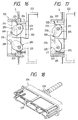
- the first connector 202 with the female-type terminals 215 thereof assembled into the male-type connector housing 214 is firstly disposed opposed to the leading end opening of the holder 201 and the connector housing 214 is then pushed in a direction of an arrow shown in Fig. 12 and is thereby inserted into the holder 201, so that the first connector 202 can be set at a connection wait position as shown by a solid line in Fig. 12.
- the projecting portions 217 of the connector housing 214 of the first connector 202 are respectively pressed against the tapered surfaces 212c of the removal prevention portions 212 provided in the horizontal plates 206 of the holder 201, so that the removal prevention portions 212 can be elastically deformed. And, the projecting portions 217 are moved beyond the securing stepped portions 212b of the removal prevention portions 212 and are then inserted into the holder 201, with the result that, as shown in Fig.
- the first connector 202 can be secured provisionally at the connection wait position where the projecting portions 218c of the provisionally securing portions 218 provided in the side surfaces of the connector housing 214 are respectively in contact with the front surfaces of the projecting portions 219 provided in the side plates 207 of the holder 201. Also, in the above-mentioned insertion operation of the first connector 202, the engaging pins 209 provided in the rear end portions of the swingable members 205 are respectively introduced into the guide grooves 210 of the holder 201, while the engaging pins 209 are engaged with the respective rear end positions of the introduction portions 210a of the guide grooves 210.
- the connector housing 220 of the second connector 204 can be fitted over the connector housing 214 of the first connector 202, so that the first and second connectors 202 and 204 can be connected together and held in electric conduction with each other.
- the swingable members 205 are respectively swung and displaced about the support shafts 211 and, in response to such oscillating displacement of the swingable members 205, the rack portions 223 of the second connector 204 are respectively driven by the pinion portions 225 of the swingable members 205 and are thereby pushed toward the first connector 202.
- the guide grooves 210 respectively include the drive groove portions 210b which extend backwardly and inwardly of the holder 201, as the first connector 202 is slid backwardly, the engaging pins 209 of the swingable members 205 are guided by the drive groove portions 210b and the rear end portions of the swingable members 205 are swung and displaced backwardly and inwardly, so that the leading end portions of the swingable members 205 are swung and displaced backwardly and outwardly.
- the distance L from the engaging pin 209 forming part of the drive part for driving the swingable members 205 to the support shaft 211 is set greater than the distance M from the rack portion 223 to the support shaft 211, in the connecting operation of the first and second connectors 202 and 204, the drive force input to the swingable members 205 according to the backward sliding motion of the first connector 202 can be increased before it is transmitted to the rack portions 223, and the second connector 204 can be pushed toward the first connector 202 with a great force, so that the first and second connectors 202 and 204 can be connected together positively.
- the first connector 202 is supported by the holder 201 mounted on the mounting portion S in such a manner that the first connector 202 can be slid in the connecting direction thereof, there are provided the swingable members 205 that can be swung and displaced according to the sliding motion of the first connector 201, and, in the swingable members 205 and second connector 204, there are further provided the pinion portions 225 and rack portions 223 which not only can increase the drive force of the swingable members 205 according to the oscillating displacement of the swingable members 205 and but also can transmit the thus increased drive force to the connected portions of the first and second connectors 202 and 204. Due to this, a great connecting force can be applied to the two connectors 202 and 204 by a simple operation, that is, by simply pushing the second connector 204 in a direction where the second connector 204 can be connected to the first connector 202.
- the two connectors 202 and 204 can be positively turned into a connected condition with one touch.
- the second connector 204 is disposed on the back side of the electronic unit 222 consisting of the meter unit, air conditioning unit, navigation device or the like of a vehicle, and the first connector 202 is mounted on the bottom portion of the mounting hole in which the electronic unit 222 is to be mounted. Due to this, even when an operator is not able to insert his or her hand into the connected portions of the two connectors 202 and 204, the two connectors 202 and 204 can be connected together easily and positively.
- the drive force can be given to the two connectors 202 and 204 by driving the swingable members 205 without securing in the installation portion of the connector an operation space for driving the swingable members 205, it is possible to prevent a dead space from being produced in the connector installation portion, which in turn makes it possible to make effective use of space.
- the swingable member 205 installation space formed between the inner wall surface of the holder 201 and the outer wall surface of the first connector 202 can be reduced in size. This makes it possible not only to effectively prevent the connector from increasing in the vertical dimensions thereof but also to positively prevent the swingable members 205 from projecting outwardly from the connector installation portion.
- the two swingable members 205 are respectively installed upwardly and downwardly of the first connector 202, the two swingable members 205 are arranged at positions which are symmetrical to each other with respect to a point, and, when viewed from a plane, the two swingable members 205 are structured such that they can be swung and displaced in the opposite direction to each other. Thanks to this structure, a great drive force can be applied to the respective end portions of the two connectors 202 and 204 on the diagonal lines thereof.
- the connecting force can be applied uniformly to the respective connected portions of the two connectors 202 and 204, thereby causing the second connector 204 to be slid and displaced straight, so that the two connectors 202 and 204 can be connected properly.
- the two swingable members 205 when the two swingable members 205 are arranged at point symmetrical positions and are structured such that they can be swung and displaced in the opposite direction to each other, since the swingable members 205 can be so formed as to have the same shape, the productivity thereof can be enhanced.
- the swingable member 205 is provided only in one of the top and bottom portions of the first connector 202, or structure in which a pair of right and left swingable members 205 are disposed on both of the top and bottom portions of the first connector 202.
- the removal prevention portions 212 are respectively provided in the upper and lower horizontal plates 206 of the holder 201, and the projecting portions 217 corresponding to the securing stepped portions 212b of such removal prevention portions 212 are respectively provided in the connector housing 214 of the first connector 202. Due to this, by bringing the projecting portions 217 into contact with the securing stepped portions 212b, the holder 201 and first connector 202 can be kept in a stably connected condition.
- the tapered surfaces 212c of the removal prevention portions 212 are respectively formed in the outer surfaces of the leading end portions of the securing stepped portions 212b, and the slits 212a are formed between the horizontal plates 206 of the holder 201 and the removal prevention portions 212. Thanks to this, when the embodiment is structured such that the projecting portions 217 can be pressed against the tapered surfaces 212c of the securing stepped portions 212b to thereby deform the removal prevention portions 212 elastically, the connecting operation of the first connector 202 to the holder 201 can be executed with one touch. Also, it is also possible that, as the need arises, by deforming the removal prevention portions 212 elastically, the first connector 202 within the holder 201 can be taken out externally of the holder 201.
- the provisionally securing portions 218 are provided on the two right and left side surfaces of the connector housing 214 of the first connector 202 and, as shown in Fig. 13, by bringing the projecting portions 218c of the provisionally securing portions 218 into contact with the front surface of the holder 201, the first connector 202 can be secured at the connection wait position provisionally. Due to this structure, it is possible to effectively prevent the first connector 202 from being pushed into the holder 201 before execution of the above-mentioned connecting operation, by use of a simple structure.
- each of the above-mentioned provisionally securing portions 218 is composed of a base end portion 218a projectingly provided on the side wall surface of the connector housing 214, a plate-shaped portion 218b which is so formed as to extend forwardly while it is disposed opposed to the side wall surface of the connector housing 214 at a given distance therefrom, and a projecting portion 218c provided on the outer surface of the leading end portion of the plate-shaped portion 218b, a pair of tapered surfaces are formed in the outer side surface of the projecting portion 218c, and a projecting portion 219 including a pair of tapered surfaces respectively corresponding to the pair of tapered surfaces of the projecting portion 218c is provided on the front surface of the holder 201, if the two tapered surface of the projecting portion 218c are contacted with the two tapered surfaces of the projecting portion 219 to thereby deform the plate-shaped portion 218b elastically, then the provisionally secured condition of the first connector 202 by the provisionally securing
- energizing means which can energize the first connector 202 forwardly, and the projecting portions 216 of the connector housing 214 may be contacted with the securing stepped portions 212b of the removal prevention portions 212 according to the energizing force of the energizing means, so that the first connector 202 can be secured at the above-mentioned connection wait position.
- the second connector 204 to be connected to the first connector 202 is mounted on the circuit board 203 provided in the electronic unit 222 but, as shown in Fig. 18, a second connector 204 including a female-type connector housing 220 and a plurality of male-type terminals 227 with harnesses 226 connected to the rear end portions thereof may be directly connected to the first connector 202.
- the holder 201 and first connector 202 are supported by the mounting portion S, but they may be structured such that an operator holds the holder 201 and first connector 202 and connects them directly to the second connector 204.
- the first connector 202 supported slidably by the holder 201 is mounted on the mounting portion S provided on the vehicle body side, and the second connector 204 to be connected to the first connector 202 is mounted on the electronic unit 222.
- the first connector 202 including the swingable members 205, male-type connector housing 214 and the like as well as the holder 201 may be installed on the electronic unit 222, and the second connector 204 including the female-type connector housing 220 and the like may be arranged on the mounting portion S.
- the electronic unit 222 serves as a mounting portion for mounting the first connector 202.
- the engaging pins 209 provided on the swingable members 205 are respectively introduced into and engaged with the guide grooves 210 formed in the holder 201
- the swingable member including a pinion portion in the leading end portion thereof is swingably supported between the holder and first connector
- the rack portions which can be meshingly engaged with the pinion portions of the swingable member
- a drive part which, in the connecting operation to connect the second connector to the first connector, can swing and displace the swing member according to the sliding motion of the first connector to thereby drive the pinion portions in a direction where the second connector is moved toward the first connector, and the distance from the drive part to the swing support point of the swingable member is set larger than the distance from the pinion portions of the swingable member to the swingable support point of the swingable member.
- the plate-shaped swingable members is interposed between the wall surface of the holder and the wall surface of the first connector opposed to the present holder wall surface, the size of the installation space, which is formed between the inner wall surface of the holder and the outer wall surface of the first connector for installation of the swingable member, can be reduced. This makes it possible not only to effectively prevent the connector increasing in the vertical dimension thereof but also to prevent the swingable member from projecting outwardly of the connector.
- a pair of swingable members are disposed in the connecting portions of the first and second connectors as well as the two swingable members are arranged at point symmetrical positions to each other, a great connecting force can be applied from the swingable members to the two end portions of the two connectors on the diagonal lines thereof according as the first connector is slid according to the drive force for connecting the first and second connectors to each other, whereby the connecting force can be applied uniformly to the respective portions of the two connectors and thus the two connectors can be connected together properly by a simple structure. Also, since the two swingable members having the same shape can be disposed on the upper and lower portions of the connector, the productivity of the swingable members can be enhanced and thus the manufacturing costs thereof can be reduced.
- the removal prevention portions for preventing the first connector held by the holder from pulled out of the holder are provided in the connecting portions of the holder and first connector, the connected condition between the holder and first connector can be maintained stably to thereby effectively prevent the first connector from being removed from the holder.
- the provisionally securing portions for securing the first connector at the connection wait position provisionally, and the provisionally secured condition of the first connector by the provisionally securing portions can be removed according to an operation force for connecting the first and second connectors to each other. Due to this structure, it is possible to prevent the first connector from being pushed into the holder before execution of the connecting operation of the two connectors and, in the connecting operation of the two connectors, the provisionally secured condition of the first connector by the provisionally securing portions can be removed with one touch.
Landscapes
- Details Of Connecting Devices For Male And Female Coupling (AREA)
Abstract
Description
- The present invention relates to a connector connecting structure which connects mutually corresponding male and female connectors to each other to thereby allow them to be in electric conduction with each other.
- Conventionally, for example, as disclosed in Unexamined Japanese Patent Publication No. 4-319271, in order to enhance the connected condition of a connector of a multi-polar structure having a large number of terminals and a large connecting resistance, there is known an electric connector of a slide connecting type. In particular, the conventional electric connector includes a holder (a slide member) which is used to hold a first connector inserted therein and includes a plurality of engaging projections formed in the upper and lower wall surfaces thereof, a second connector which is formed in a substantially rectangular shape and includes not only a recessed portion into which the holder can be inserted but also an opening formed in the side wall thereof substantially in parallel to the side wall, and a substantially U-shaped operation member including a cam grooves which is engageable with the engaging projections of the holder, wherein the first and second connectors can be connected to each other by sliding the operation member.
- Referring further to the structure of the above-mentioned conventional electric connector of a sliding connection type, after the first connector is inserted into and held by the holder, a plate-shaped portion of the operation member is inserted into the opening formed in the side wall of the second connector, the engaging projections of the holder holding the first connector inserted therein are matched in position to the cam groove of the operation member and are then engaged therewith, and, in such engaged condition, the operation member is pushed in the longitudinal direction of the holder to thereby slide the engaging projections of the holder along the cam groove of the operation member, so that the first connector held by the holder can be connected to the second connector.
- In the above-mentioned conventional structure, the second connector engaged with the operation member is provisionally engaged with the first connector held by the holder, and the engaging projections formed in the holder are matched in position to the cam groove formed in the operation member. After then, by pushing the operation member in the longitudinal direction of the holder, the first connector must be connected to the second connector. That is, in this structure, the connecting operation must be executed at two or more stages, which is troublesome.
- Especially, when one of the two connectors is mounted on the leading end portion side of an electronic unit such as a meter unit, an air conditioning unit or the like to be mounted on an instrumental panel of a vehicle, once the electronic unit is assembled into the instrumental panel, the operation portion of the operation member cannot be driven and, therefore, the electronic unit must be assembled into the instrumental panel after the above connector is connected to the other connector, which results in the very troublesome assembling operation.
- Also, after the connector connecting operation is completed, since the plate-shaped portion of the operation member is inserted into the second connector, the width dimension of the connector can be reduced. However, before the connector connecting operation is executed, because the operation member projects out laterally of the connector to a great extent, it is necessary to secure a space for operation of the operation member, which raises a problem that a large dead space is inevitably produced.
- Furthermore, for example, as disclosed in Unexamined Japanese Patent Publication No. 3-194871, in order to enhance the connected condition of a connector of a multi-polar structure which includes a large number of terminals and shows a large connecting resistance, there is known a multi-polar connector of a low insertion force type in which, in one connector, a pinion is rotatably supported and a slide rack piece member to be engaged with the pinion is slidably supported, and, in the other connector, there is provided a fixing rack portion to be engaged with the pinion of one connector, whereby, if the slide rack piece member is operated or slid to thereby drive or rotate the pinion, then the two connectors can be connected to each other.
- That is, the above-mentioned conventional low insertion force multi-polar connector is structured such that a male connector housing forming one connector is provisionally fitted with a female connector housing forming the other connector to thereby bring the pinion supported in the male connector housing into meshing engagement with the front portion of the fixing rack portion formed in the female connector housing and, after then, if an operator pushes in the slide rack piece member supported in the male connector housing by his or her finger to thereby cause the same to slide, then the slide rack piece member is allowed to roll on the fixing rack portion while the pinion is being rotated, thereby applying a forwardly advancing force to the pinion, so that the two connectors can be connected together.
- In the conventional connector having the above-mentioned structure, since the two connectors can be connected together by pushing the slide rack piece member in the same direction as the connecting direction of the two connectors, the connecting operation can be carried out comparatively easily. However, after the connector housings of the two connectors are provisionally fitted with each other, it is necessary to fit the male and female connector housings with each other by pushing the slide rack piece member. That is, this connecting operation must be executed in at least two stages.
- In particular, when one of the two connectors is mounted on the leading end portion side of an electronic unit such as a meter unit, an air conditioning unit or other similar units to be assembled to the instrumental panel of a vehicle, once the electronic unit is assembled to the instrumental panel, the operation portion of the slide rack piece member cannot be driven any longer. For this reason, the electronic unit must be assembled to the instrumental panel after the two connectors are connected together, which results in the troublesome assembling operation.
- Also, after the connecting operation of the two connectors is completed, since most of the slide rack piece member are inserted into the female connector housing, the installation space for the connector can be reduced. However, before the connector connecting operation is carried out, the pushing operation portion of the slide rack piece member is projected out backwardly of the connector, which makes it necessary to secure an operation space for operation of the slide rack piece member. That is, a dead space is inevitably produced.
- The present invention aims at eliminating the drawbacks found in the above-mentioned conventional connector connecting structure. Accordingly, it is an object of the invention to provide a connector connecting structure which is able to connect a pair of connectors to each other positively by a simple operation and is also able to reduce a connector installation space.
- In attaining the above object, according to the first aspect of the invention, there is provided a connector connecting structure comprising a first connector supported by a holder and a second connector to be connected to the first connector, wherein there is provided in the holder a support portion for supporting the first connector in such a manner that the first connector can be slid in the connecting direction of the first and second connectors, and a slide member slidingly displaceable in a direction at right angles to the connecting direction of the two connectors is supported between the holder and said second connector, and also wherein there are further provided a drive part for sliding and displacing the slide member according to the sliding displacement of the first connector, and an operation part for increasing the drive force of the slide member and transmitting the thus increased drive force to the connecting portions of the first and second connectors to thereby be able to drive the two connectors in the connecting direction thereof.
- According to the above-mentioned structure, if the first connector is slid and displaced along the holder according to the operation force for connecting the first and second connectors, then the slide member is slid and displaced according to the drive force input therein from the drive part, and the drive force is increased and transmitted from the operation part to the connecting portion of the two connectors, so that a great connecting force can be applied to the two connectors.
- Further, according to the invention, a plate-shaped slide member is interposed between the inner wall surface of the holder and the outer wall surface of the first connector.
- According to the above-mentioned structure, since a plate-shaped slide member having a small thickness is interposed between the holder and first plate, the installation space of the slide member can be controlled down to a small space, which makes it possible to reduce the size of the connector.
- Further, according to the invention, a pair of slide members are respectively so provided as to extend along the mutually opposed wall surfaces of the holder, and the two slide members are arranged at point symmetrical positions to each other.
- According to the above-mentioned structure, if the first connector is slid and displaced along the holder according to the drive force for connecting together the first and second connectors, then a great connecting force can be applied from the two slide members to the two diagonally positioned end portions of the two connectors.
- Still further, according to the invention, in the connecting portion of the holder and first connector, there is provided a removal prevention portion which is used to prevent the first connector from being pulled out forwardly from the holder.
- According to the above-mentioned structure, provision of the removal prevention portion prevents the possibility that the first connector inserted into the holder can be pulled out from the holder and the connected condition between the holder and first connector can be thereby removed.
- Yet further, according to the invention, in the connecting portion of the holder and first connector, there is provided a provisionally securing portion which is used to secure the first connector at a connection wait position provisionally, and the provisionally secured condition of the first connector by the provisionally securing portion can be removed according to the operation force for connecting the first and second connectors to each other.
- According to the above-mentioned structure, before the two connectors are connected together, the first connector can be provisionally secured at the connection wait position by the provisionally securing portion and, in the two connectors connecting operation, the provisionally secured condition of the first connector by the provisionally securing portion can be removed and thus the first connector can be slid and displaced along the holder.
- In attaining the above object, according to the second aspect of the invention, there is provided a connector connecting structure comprising a first connector supported slidably by a holder and a second connector to be connected to the first connector, wherein a swingable member including a pinion portion in the leading end portion thereof is swingably supported between the holder and first connector, there is provided in the connector a rack portion meshingly engageable with the pinion portion of the swingable member, there is provided a drive part which, in an operation to connect the second connector to-the first connector, can swing and displace the swingable member according to the sliding motion of the first connector to thereby drive the pinion portion in a direction where the second connector is moved toward the first connector, and a distance from the drive part to the swing support point of the swingable member is set larger than a distance from the pinion portion of the swingable member to the swing support point of the swingable member.
- According to the above-mentioned structure, if the first connector is slid along the holder according to an operation force for connecting the first and second connectors to each other, then the swingable member is driven by the drive part and is thereby swung and displaced and, at the same time, the drive force of the swingable member is increased according to the principles of leverage and the thus increased drive force is then transmitted from the pinion portion of the swingable member to the rack portion of the second connector in meshing engagement with the pinion portion of the swingable member, so that the second connector can be driven or moved toward the first connector with a great force.
- Also, according to the invention, a plate-shaped swingable member is interposed between the wall surface of the holder and the wall surface of the first connector that is opposed to the present holder wall surface.
- According to the above-mentioned structure, since a swingable member having a small plate thickness is interposed between the holder and first connector, an installation space necessary for installation of this swingable member can be reduced down to a small space, which makes it possible to supply a compact connector.
- Further, according to the invention, a pair of swingable members are respectively installed along the mutually opposed wall surfaces of the holder, and the two swingable members are arranged at positions symmetrical to each other with respect to a point.
- According to the above-mentioned structure, if the first connector is slid along the holder according to a drive force for connecting the first and second connectors to each other, then a great connecting force can be applied from the two swingable members to the two end portions of the two connectors on the diagonal lines thereof.
- According to the invention, in the connecting portion of the holder and first connector, there is provided a removal prevention portion which is used to prevent the first connector from being pulled out forwardly from the holder.
- According to the above-mentioned structure, the removal prevention portion eliminates the possibility that the first connector supported within the holder can be pulled out from the holder to thereby remove the connected condition between the holder and first connector.
- According to the invention, in the connecting portion of the holder and first connector, there is provided a provisionally securing portion which secures the first connector provisionally at a connection wait position, and the provisionally secured condition of the first connector by the provisionally securing portion can be removed according to an operation force for connecting the first and second connectors to each other.
- According to the above-mentioned structure, before the two connectors are connected together, the first connector is provisionally secured at the connection wait position by the provisionally securing portion and, in the connecting operation of the two connectors, the provisionally secured condition of the first connector by the provisionally securing portion can be removed automatically so that the first connector can be slid along the holder.
-
- Fig. 1 is a perspective view of first embodiment of a connector connecting structure according to the invention;
- Fig. 2 is an exploded perspective view of a concrete structure of a first connector employed in the embodiment;
- Fig. 3 is a sectional side view of the first embodiment, showing a state in which the first connector is secured by removal prevention portions;
- Fig. 4 is a sectional plan view of the first embodiment, showing a state in which the first connector is secured at a connection wait position provisionally;
- Fig. 5 is a perspective view of a concrete structure of a second connector employed in the first embodiment; Fig. 6 is a sectional plan view of the first embodiment, showing a state thereof before the first and second connectors are connected to each other;
- Fig. 7 is a sectional plan view of the first embodiment, showing a connecting process in which the first and second connectors are connected to each other;
- Fig. 8 is a sectional plan view of the first embodiment, showing the connected condition of the first and second connectors;
- Fig. 9 is a perspective view of another embodiment of the second connector;
- Fig. 10 is a perspective view of second embodiment of a connector connecting structure according to the invention;
- Fig. 11 is an exploded perspective view of a concrete structure of a first connector employed in the second embodiment;
- Fig. 12 is a sectional side view of the second embodiment, showing a state thereof in which the first connector is secured to a holder by means of removal prevention portions;
- Fig. 13 is a sectional plan view of the second embodiment, showing a state thereof in which the first connector is provisionally secured at a connection wait position by means of provisionally securing portions;
- Fig. 14 is a perspective view of a concrete structure of a second connector employed in the second embodiment;
- Fig. 15 is a sectional plan view of the second embodiment, showing a state thereof before the first and second connectors are connected to each other;
- Fig. 16 is a sectional plan view of the second embodiment, showing a process for connecting the first and second connectors to each other;
- Fig. 17 is a sectional plan view of the second embodiment, showing the connected condition of the first and second connectors; and
- Fig. 18 is a perspective view of another embodiment of the second connector.
- Now, Fig. 1 shows a first embodiment of a connector connecting structure according to the invention. The present connector comprises a
holder 101 mounted on a mounting portion S which consists of a stay member or the like provided in a vehicle, afirst connector 102 supported slidably by theholder 101, asecond connector 104 mounted on acircuit board 103 which forms anelectronic unit 122, and a pair ofslide members 105 which are respectively used to drive thesecond connector 104 in a direction where thesecond connector 104 can be connected to thefirst connector 102. - The
holder 101, as shown in Fig. 2, is formed in a tubular shape which includes a pair of top and bottomhorizontal plates 106 and a pair of right and leftside plates 107, while theholder 101 can be fitted into a mounting hole formed in the mounting portion S of the vehicle body and can be fixed thereto by a screw or similar fixing means. And, in the respective wall surfaces of the two right and leftside plates 107 of theholder 101, there are formed support portions which respectively extend in the horizontal direction thereof and respectively consist of a pair of upper and lower recessedgrooves 108 used to support thefirst connector 102 in a such a manner that it can be freely slid. - Each of the
slide members 105 includes a pair of engagingpins 109 which are respectively provided on and projected from the upper surface of the rear end portion of theslide member 105. In thehorizontal plate 106, there are formed a pair ofguide grooves 110 which are arranged in parallel to each other. The twoengaging pins 109 can be engaged with the twoguide grooves 110, respectively. Each of theguide grooves 110 includes anintroduction portion 110a extending backwardly from the front end portion of theholder 101, adrive groove portion 110b backwardly and inwardly from the rear portion of theintroduction portion 110a, and a securingportion 110c extending backwardly from the end portion of thedrive groove portion 110b. In the present embodiment, thedrive groove portion 110b is formed such that it extends backwardly and inwardly of the rear portion of theholder 101 in a straight line. However, the drive groove portion may also be formed such that it extends backwardly and inwardly from the end portion of theintroduction portion 110a in a curved line. - Also, the
guide groove 110 formed in the upperhorizontal plate 106 is symmetrical to theguide groove 110 formed in the lowerhorizontal plate 106. That is, in the present embodiment, when viewed from the front surface side of theholder 101, a pair ofguide grooves 110 are formed in parallel to each other on the right side of the upperhorizontal plate 106, while a pair ofguide grooves 110 are formed in parallel to each other on the left side of the lowerhorizontal plate 106. - The
horizontal plates 106 of theholder 101, as shown in Fig. 3, includeslits 112a which are respectively formed on the right and left portions of the inner wall surfaces of thehorizontal plates 106 and also which respectively have a given width. Due to provision of theslits 112a, there is provided aremoval prevention portion 112 which secures thefirst connector 102 at its forward wait position, while theremoval prevention portion 112 includes in the leading end portion thereof securing steppedportions 112b which are respectively opposed to projectingportions 117 formed in the rear portion of thefirst connector 102. And, in operation, the front surfaces of the projectingportions 117 are contacted with the rear surfaces of the securing steppedportions 112b to thereby be able to prevent the first connector from being removed forwardly from the holder. Also, each of the securing steppedportions 112b includes a tapered surface on the outer surface of the leading end portion thereof, so that the securing steppedportion 112b has a forwardly tapered shape. - The
first connector 102 includes a male-type connector housing 114 which can be inserted into theholder 101 and can be supported slidably therein, and a plurality of female-type terminals which are disposed within a terminal storage chamber formed in theconnector housing 114. Theconnector housing 114 includes a pair of upper and lower projectingportions 116 which are respectively formed on the right and left side surfaces of the rear end portion of theconnector housing 114 in such a manner that they can be slid along the recessedgrooves 108 of theholder 101. Also, theconnector housing 114 further includes projectingportions 117 which are provided on the right and left sides of the upper and lower surfaces of the rear end portion thereof in such a manner that they can be secured to the securing steppedportions 112b of theremoval prevention portion 112. - Also, on the right and left side surfaces of the
connector housing 114, as shown in Fig. 4, there are formed provisionally securingportions 118 which are used to secure thefirst connector 102 provisionally at the above-mentioned connection wait position to thereby prevent thefirst connector 102 from being pushed into theholder 101 before the execution of a connectors connecting operation to be described later. Each of the provisionally securingportions 118 includes abase end portion 118a projectingly provided on the side wall surface of theconnector housing 114, a plate-shapedportion 118b which extends backwardly while it is opposed to the side wall surface of theconnector housing 114 with a given clearance between them, and a projectingportion 118c which is projectingly provided on the outer surface of the rear portion of the plate-shapedportion 118b. - The projecting
portion 118c of the provisionally securingportion 118, when viewed from a plane thereof, is so formed as to have a triangular shape and, on the outer side surface thereof, there are formed a pair of tapered surfaces. Also, on the front surface of theholder 101, there is provided aprojection 119 including a pair of tapered surfaces corresponding to the tapered surfaces of the projectingportion 118c. And, in operation, the rear tapered surface of the projectingportion 118c provided in the provisionally securingportion 118 is contacted with the front tapered surface of theprojection 119 provided on theholder 101 to thereby be able to secure thefirst connector 102 provisionally at the connection wait position. - The
second connector 104, as shown in Fig. 5, includes a female-type connector housing 120 which can be fitted over and engaged with theconnector housing 114 of thefirst connector 102, and a plurality of male-type terminals 121 disposed within a terminal storage chamber formed in theconnector housing 120. Theconnector housing 120 is fixed onto thecircuit board 103 by screwing or by other similar fixing means, while the connectingportions 121a of the male-type terminals 121 are respectively guided out from the rear end portion of theconnector housing 120 and are connected to the introduction portion of thecircuit board 103 by soldering or by other similar connecting means (see Fig. 1). - Also, the
second connector 104 andcircuit board 103 are respectively stored within a case for anelectronic unit 122. Theconnector housing 120 further includes on the outer surface thereof a pair of drivenpins 123 which can be driven by theslide member 105, while the drivenpins 123 are projectingly provided at a position opposed to the installation position of theslide member 105. - The above-mentioned
slide members 105 are respectively formed of plate members interposed between the inner wall surfaces of theholder 101, which are composed of the lower surface of the upperhorizontal plate 106 and the upper surface of the lowerhorizontal plate 106 respectively forming theholder 101, and the outer wall surfaces of thefirst connector 102 which are composed of the upper and lower surfaces of theconnector housing 114. Also, as shown in Figs. 2 and 6, each of theslide members 105 is slidably supported by a pair of connectingpins 111 projectingly provided on theconnector housing 114 of thefirst connector 102 at a position which is opposed to theguide groove 110 formed in theholder 101. - That is, in the
slide member 105, there is formed aguide groove 124 which extends laterally (longitudinally) of theholder 101 andfirst connector 102 and, thus, if the pair of connectingpins 111 are fitted into thepresent guide groove 124, then theslide member 105 is supported in such a manner that not only the oscillating displacement of theslide member 105 can be restricted by the two connectingpins 111 but also theslide member 105 is allowed to be slid and displaced in a direction at right angles to the connecting direction of the twoconnectors guide groove 124. Here, it should be noted that the slidingly displacing direction of theslide member 105 is not always limited to the above direction that extends exactly at right angles to the connecting direction of the twoconnectors - Also, on the outer surfaces of the respective rear end portions of the upper and
lower slide members 105, that is, on the upper surface of the rear end portion of theupper slide member 105 and on the lower surface of the rear end portion of thelower slide member 105, there are respectively providedengaging pins 109 which can be fitted into theguide grooves 110 respectively. At the same time, on the portion of theslide member 105 that is situated forwardly of theguide groove 124, there are formed a pair of engaginggrooves 125 into which two drivenpins 123 can be fitted respectively, while the two drivenpins 123 are projectingly provided on the upper and lower portions of theconnector housing 120 of thesecond connector 104. - Each of the two
engaging grooves 125 of theslide member 105 is composed of anopening portion 125a, which serves as an introduction and guide portion for its corresponding drivenpin 123, and anoperation groove portion 125b which continues with theopening portion 125a and extends outwardly of the rear portion of theslide member 105. Theoperation groove portion 125b is formed such that the width direction dimension thereof is set substantially the same as the width dimension of thedrive groove portion 110b of theholder 101 and the longitudinal direction dimension thereof is set for a value smaller than the value of the longitudinal direction dimension of thedrive groove portion 110b of theholder 101, whereby the directions of inclination of theoperation groove portion 125b and drivegroove portion 110b are set such that the angle of inclination of theoperation groove portion 125b with respect to the width direction of the connector is smaller than the angle of inclination of thedrive groove portion 110b formed in theholder 101. - As described above, since the direction of inclination of the
operation groove portion 125a formed in theslide member 105 is set opposite to the direction of inclination of thedrive groove portion 110b formed in theholder 101, when the twoconnectors first connector 102 is pushed into theholder 101, theslide members 105 are slid and displaced (which will be discussed later) to thereby transmit a drive force from the engaginggrooves 125 of theslide member 105 to the drivenpins 123, so that thesecond connector 104 can be driven or drawn toward thefirst connector 102. - Also, since the directions of inclination of the
operation groove portions 125b and drivegroove portions 110b are set such that the angle of inclination of theoperation groove portions 125b with respect to the width direction of the connector is smaller than the angle of inclination of thedrive groove portions 110b formed in theholder 101, the amount of movement of thesecond connector 104 in the above-mentioned connecting direction is smaller than the amount of movement of thefirst connector 102 when it is pushed into theholder 101 according to the connecting operation force for connecting together the twoconnectors drive groove portions 110b to theslide members 105 can be increased before it is transmitted to thesecond connector 104. - That is, the
drive groove portions 110b of theguide grooves 110 respectively formed in theholder 101 and the engagingpins 109 to be fitted into thedrive groove portions 110b cooperate in forming a drive part which, according to the sliding displacement of thefirst connector 102, drives theslide members 105 so that they are slid and displaced; and, theoperation groove portions 125b of the engaginggrooves 125 respectively formed in theslide members 105 and the drivenpins 123 to be engaged with theoperation groove portions 125b cooperate in forming an operation part which increases the drive force of theslide members 105 and transmits the thus increased drive force to the connecting portions of the first andsecond connectors connectors - To connect together the above-structured first and
second connectors first connector 102 having their female-type terminals 115 assembled into the male-type connector housing 114 is disposed opposingly to the opening of the leading end portion of theholder 101 as shown by a virtual line in Fig. 3 and, after then, theconnector housing 114 is pushed in a direction of an arrow shown in Fig. 3 and is inserted into theholder 101, so that thefirst connector 102 can be set at a connection wait position as shown by a solid line in Fig. 3. - In other words, as the
first connector 102 is inserted into theholder 101, the projectingportions 117 of theconnector housing 114 are respectively pressed against the taperedsurfaces 112c of theremoval prevention portions 112 provided in thehorizontal plates 106 of theholder 101, so that theremoval prevention portions 112 are elastically deformed. And, the projectingportions 117 are fitted into theholder 101 beyond the securing steppedportions 112b of theremoval prevention portions 112 and, as shown in Fig. 4, thefirst connector 102 is provisionally secured at the connection wait position where the projectingportions 118c of the provisionally securingportions 118 provided on the side surfaces of theconnector housing 114 are brought into contact with the front surfaces of theprojections 119 respectively provided on the twoside plates 107 of theholder 101. Also, in the above-mentioned insertion operation of thefirst connector 102, the engagingpins 109 provided on the rear end portions of theslide members 105 are respectively introduced into theguide grooves 110 of theholder 101 and the engagingpins 109 are respectively engaged with the rear end positions of theintroduction portions 110a of theguide grooves 110. - Next, after the
holder 101 is mounted onto the mounting portion S of the vehicle body, if theelectronic unit 122 with thesecond connector 104 mounted thereon is disposed opposingly to the installation position of thefirst connector 102 and is pushed toward thefirst connector 102, then theconnector housing 120 of thesecond connector 104 can be fitted over and assembled with theconnector housing 114 of thefirst connector 120, so that the first andsecond connectors - Since the
first connector 102 is pushed backwardly by thesecond connector 104 in response to the connecting operation of the twoconnectors portions 118c of the provisionally securingportions 118 provided on the side surfaces of thesecond connector 104 are respectively pressed against theprojections 119 of theholder 101, so that the plate-shapedportions 118b of the provisionally securingportions 118 are elastically deformed. And, after the projectingportions 118c of the provisionally securingportions 118 are moved beyond theprojections 119 of theholder 101, not only theconnector housing 114 of thefirst connector 102, as shown in Fig. 7, is slid and displaced backwardly along the inner wall surface of theholder 101, but also the drivenpins 123 of thesecond connector 104 are respectively introduced into the engaginggrooves 125 of theslide members 105 so that the drivenpins 123 can be engaged with theslide members 105. - Also, due to the fact that the engaging
pins 109 of theslide members 105 are slid backwardly and inwardly along thedrive groove portions 110b of theguide grooves 110 in response to the backward sliding displacement of thefirst connector 102, theslide members 105 are slid and displaced toward the central portion of thefirst connector 102 while they are being supported by the connectingpins 111 and, in response to the sliding displacement of theslide members 105, the drivenpins 123 of thesecond connector 104 are driven by theslide members 105 and are thereby drawn toward thefirst connector 102. - That is, because the
operation groove portions 125b extending backwardly and inwardly are formed in the engaginggrooves 125 of theslide members 105 engaged with the drivenpins 123, when theoperation groove portions 125b are slid and displaced along the drivenpins 123 of thesecond connector 104 in response to the sliding displacement of theslide members 105, then the drivenpins 123 are drawn toward the connectingpins 111 and, after then, the twoconnectors - Also, the inclination angle of the
drive groove portions 110b forming the drive part for driving theslide members 105 with respect to the connecting direction of the twoconnectors operation groove portions 125b forming the operation part for driving thesecond connector 104, so that, in the above-mentioned connecting operation of the first andsecond connectors slide members 105 can be increased according as thefirst connector 102 is slid and displaced backwardly and the thus increased drive force can be transmitted to the driven pins 123. Due to this, according to such drive force, thesecond connector 104 can be pushed toward thefirst connector 102 with a great force, so that the first andsecond connectors - And, in the connected condition of the first and
second connectors pins 109 of theslide members 105 are respectively introduced and locked into the securingportions 110c of theguide grooves 110. Therefore, even if the connecting portions of the twoconnectors pins 109 are thereby moved forwardly to a slight extent, there is no possibility that the drive force for sliding and displacing theslide member 105 can be given to the twoconnectors connectors securing portions 110c, the first andsecond connectors slide members 105 are integrally moved backwardly of theholder 101, even if the amount of push-in movement of theelectronic unit 122 varies to some extent, the twoconnectors - To remove the above-mentioned connected condition between the first and
second connectors electronic unit 122 is pulled to thereby slide and displace thesecond connector 104 to a connection removing position, then theslide members 105 can be slid and displaced in the opposite direction to the above-mentioned connecting operation and thefirst connector 102 can slid and displaced forwardly, so that the twoconnectors - According to the present embodiment, as described above, the
first connector 102 is supported by theholder 101 mounted on the mounting portion S of the vehicle body in such a manner that thefirst connector 102 can be slid in the connecting direction thereof, theslide members 105 are provided in such a manner that they can be slid and displaced in a direction at right angles to the connecting direction of the twoconnectors first connector 102, and the drive force of theslide members 105 can be increased according to the sliding displacement thereof and the thus increased drive force of theslide members 105 can be transmitted to the connecting portions of the first andsecond connectors connectors connectors second connector 104 in a direction where it can be connected with thefirst connector 102. - Therefore, even in a connector of a multi-polar structure in which a large number of female-
type terminals 115 and male-type terminals 121 are disposed in the first andsecond connectors 104, the twoconnectors second connector 104 is disposed on the back surface side of theelectronic unit 122 comprising the meter unit, air conditioning unit, navigation device or the like of the vehicle and also in which thefirst connector 102 is mounted on the bottom portion of a mounting hole in which suchelectronic unit 122 is to be mounted, that is, even in a case in which it is impossible to insert the hand of an operator into the connecting portions of the twoconnectors connectors - Further, since the connecting operation of the two
connectors slide member 105 without securing an operation space for driving theslide member 105 laterally of the installation portion of the connector, there is eliminated the need to provide a large dead space laterally of the installation portion of the connector, thereby being able to make effective use of the space of the connector. - Still further, according to the above-mentioned embodiment, because the plate-shaped
slide members 105 are interposed between the inner wall surface of theholder 101 and the outer wall surface of thefirst connector 102, it is possible to reduce the slide members installation space formed between the inner wall surface of theholder 101 and the outer wall surface of thefirst connector 102, which in turn makes it possible to effectively prevent the connector from increasing in the vertical dimension thereof. - According to a further aspect of the above-mentioned embodiment, the two
slide members 105 are respectively arranged on the top and bottom portions of thefirst connector 104, whereby not only the twoslide members 105 can be supported in such a manner that they can be freely slid along the mutually opposing wall surfaces of theholder 101 but also the twoslide members 105 can be arranged at symmetrical positions to each other. Due to this structure, while the twoslide members 105 are being slid and displaced toward the central portion of the connector, if a great drive force is given to the respective two end portions of the twoslide members 105 on the diagonal line of the twoconnectors connectors connectors - Also, in the above-mentioned case where the two
connectors 105 are arranged at symmetrical positions, theslide members 105 can be formed in the same shape, thereby being able to improve the productivity of theslide members 105. For reference, instead of use of the above-mentioned structure, it is also possible to employ a structure in which theslide member 105 is provided only on one of the top and bottom portion of thefirst connector 102, or a structure in which a pair of right and leftslide members 105 are respectively provided on both of the top and bottom portions of thefirst connector 102. - According to a still further aspect of the above-mentioned embodiment, the
removal prevention portions 112 are respectively formed in thehorizontal plates 106 of theholder 101 and the projectingportions 117 corresponding to the securing steppedportions 112b of theremoval prevention portions 112 are provided on theconnector housing 114 of thefirst connector 102. Due to this, by bringing the projectingportions 117 into contact with the securing steppedportions 112b, theholder 101 andfirst connector 102 can be kept in a stably connected condition. - Also, as mentioned above, the
tapered surfaces 112c are respectively formed in the outer surfaces of the leading end portions of the securing steppedportions 112b, and theslits 112a are respectively interposed between thehorizontal plates 106 andremoval prevention portions 112 of theholder 101. Therefore, in a structure in which the projectingportions 117 of theconnector housing 114 can be respectively pressed against the taperedsurfaces 112c of the securing steppedportions 112c and theremoval prevention portions 112 can be thereby deformed elastically, a connecting operation to connect thefirst connector 102 to theholder 101 can be executed easily with one touch. Further, by deforming theremoval prevention portions 112 elastically, thefirst connector 102 within theholder 101 can also be taken out of theholder 101. - According to another aspect of the above-mentioned embodiment, the provisionally securing
portions 118 are formed on the two right and left side surfaces of theconnector housing 114 and, as shown in Fig. 4, the projectingportions 118c of the provisionally securingportions 118 are contacted with the front surface of theholder 101 so that thefirst connector 101 can be secured provisionally at the connection wait position. Thanks to this, the possibility that thefirst connector 102 can be pushed into theholder 101 prior to execution of the above-mentioned connectors connecting operation can be prevented effectively by a simple structure. - And, when each of the provisionally securing
portions 118 is composed of the base end portion 18a provided on and projected from the side wall surface of theconnector housing 114, the plate-shaped portion 18b which is disposed opposed to the side wall surface of theconnector housing 114 at a given space therefrom and also which extends forwardly, and the projectingportion 118c which is provided on the outer surface of the leading end portion of the plate-shapedportion 118b, a pair of tapered surfaces are formed in the outer side surface of the projectingportion 118c, and there is provided on the front surface of theholder 101 theprojection 119 which includes a pair of tapered surfaces corresponding to the pair of tapered surfaces of the projectingportion 118c, if the tapered surfaces are respectively pressed against each other to thereby deform the plate-shapedportion 118b elastically, then the provisionally secured condition of thefirst connector 102 by the provisionally securingportions 118 can be removed easily with one touch. - However, instead of the provisionally securing
portions 118, it is also possible to employ another structure in which there is provided an energizing member for energizing thefirst connector 102 forwardly, and the projectingportions 116 of theconnector housing 114 are respectively contacted with the securing steppedportions 112b of theremoval prevention portions 112 according to the energizing force of the energizing member, thereby being able to secure thefirst connector 102 at the above-mentioned connection wait position. - Also, it is not always necessary that the
second connector 104 to be connected to thefirst connector 102 is mounted on thecircuit board 103 provided in theelectronic unit 122 but, as shown in Fig. 9, asecond connector 104, which includes a female-type connector housing 120 and a plurality of male-type terminals 127 respectively havingharnesses 126 connected to the rear end portions thereof, may be directly connected to the above-mentionedfirst connector 102. Further, it is not always necessary that theholder 101 andfirst connector 102 are supported on the mounting portion S of the vehicle body, but it is also possible to employ a structure in which an operator holds theholder 101 andfirst connector 102 by hand and connects them to the abovementionedsecond connector 104 directly. - In the above-mentioned embodiment, description has been given of the case in which the
first connector 102 supported slidably by theholder 101 is mounted on the mounting portion S of the vehicle body and thesecond connector 104 to be connected to thefirst connector 102 is mounted in theelectronic unit 122. However, this is not limitative but it is also possible to employ a structure in which afirst connector 102 includingslide members 105, a male-type connector housing 114 and the like as well as theholder 101 are installed in the above-mentionedelectronic unit 122, and asecond connector 104 including a female-type connector housing 120 and the like is disposed in the above-mentioned mounting portion S. In this case, theelectronic unit 122 is used as a mounting portion for mounting thefirst connector 102 thereon. - Also, instead of the above structure in which the engaging
pins 109 projectingly provided on theslide members 105 are introduced into and engaged with theguide grooves 110 formed in theconnector housing 114 of thefirst connector 102, there may be employed a structure in which engagingpins 109 are provided on the above-mentionedconnector housing 114 and guidegrooves 110 engageable by thepresent engaging pins 9 are formed in the above-mentionedslide members 105. Further, it is also possible to employ another structure of a type that drivenpins 123 are projectingly provided on the lower surfaces of the leading end portions of the above-mentionedslide members 105 and engaginggrooves 125 into which the present drivenpins 123 can be introduced for engagement are respectively formed in theconnector housing 120 of the above-mentionedsecond connector 104. - Further, in the above-mentioned embodiment, description has been given of the case in which the
slide members 105 are slidably supported on theconnector housing 114 of thefirst connector 102 and the drive parts for sliding and displacing theslide members 105 are interposed between theslider members 105 andholder 101. However, this is not limitative but it is also possible to employ a structure in which the above-mentioned connectingpins 11 and guidegrooves 124 for supporting theslide members 105 slidably in theholder 101 are respectively interposed between theslide members 105 andholder 101 to thereby allow theholder 101 to support theslide members 105, and a drive part consisting of the above-mentionedengaging pins 109 and guidegrooves 110 is interposed between theconnector housing 114 of thefirst connector 102 andslide members 105. - As has been described heretofore, according to the first aspect of the invention, there is provided in a holder a support portion for supporting a first connector in such a manner that the first connector can be slid in a direction where first and second connectors can be connected, and there is provided a slide member which can be slid and displaced in a direction at right angles to the connecting direction of the two connectors according to the sliding displacement of the first connector, whereby a drive force input to the two slide members can be increased and the thus increased drive force can be transmitted to the connecting portions of the first and second connectors, so that the two connectors can be driven in a direction where they can be connected together. Due to this structure, a strong connecting force can be applied to the connecting portions of the two connectors by a one-touch operation to connect the second connector to the first connector. Therefore, even when a connector of a multipolar structure having a large connecting resistance is disposed at a position into which an operator cannot insert his or her hand, the connecting operation of the two connectors can be executed easily and positively as well as it is possible to prevent a dead space from being generated laterally of the present connector, thereby being able to control the installation space of the connector down to a minimum.
- Also, according to the invention, since a plate-shaped slide member is interposed between the inner wall surface of the holder and the outer wall surface of the first connector, the installation space of the slide member formed between the inner wall surface of the holder and the outer wall surface of the first connector can be reduced, which makes it possible to effectively prevent the connector from increasing in the vertical dimension thereof.
- Further, according to the invention, a pair of slide members are installed in the connecting portions of the first and second connectors and the two slide members are arranged at symmetrical positions to each other. Due to this, as the first connector is slid and displaced according to the drive force for connecting the first and second connectors, if a great connecting force is applied to the two diagonally located end portions of the two connectors from the two slide members, then uniform connecting forces can be applied to the respective parts of the two connectors and thus the two connectors can be connected together properly by a simple structure. Also, because the two slide members having the same shape can be disposed on the top and bottom portions of the first connector, the productivity of the slide members can be improved and thus the manufacturing costs thereof can be reduced.
- Still further, according to the invention, since there is formed in the connecting portion of the holder and first connector a removal prevention portion which is used to prevent the first connector supported by the holder from being pulled out of the holder, the connected condition of the holder and first connector can be maintained stably, that is, it is possible to effectively prevent the possibility that the first connector can be removed from the holder.
- Yet further, according to the invention, in the connecting portion of the holder and first connector, there is provided a provisionally securing portion for securing the first connector at a connection wait position thereof provisionally and the provisionally secured condition of the first connector by the provisionally securing portion can be removed according to an operation force for connecting the first and second connectors to each other. Due to this structure, not only it is possible to prevent the possibility that the first connector can be pushed into the holder prior to execution of the connecting operation of the two connectors but also, in the two connectors connecting operation, the provisionally secured condition of the first connector by the provisionally securing portion can be removed with one touch.
- Now, Fig. 10 shows a second embodiment of a connector connecting structure according to the invention. The present connector comprises a
holder 201 mounted on a mounting portion S which consists of a stay member of a vehicle or the like, afirst connector 202 supported slidably by theholder 201, asecond connector 204 mounted on acircuit board 203 which forms part of anelectronic unit 222, and two upper and lowerswingable members 205 are respectively used to drive thesecond connector 204 in a direction where thesecond connector 204 can be connected to thefirst connector 202. - The above-mentioned
holder 201, as shown in Fig. 11, is so formed as to have a tubular shape which includes a pair of upper and lowerhorizontal plates 202 and a pair of right and leftside plates 207, while theholder 201 is also structured such that it can be fitted into a mounting hole formed in the mounting portion S and can be fixed thereto by screwing or by similar fixing means. Also, in the respective inner wall surfaces of the two right and leftside plates 207, there are formed support portions which respectively extend in the horizontal direction and are used to support thefirst connector 202 in a freely slidable manner, while each of the support portions consists of a pair of upper and lower recessedgrooves 208. - Each of the
swingable members 205 includes anengaging pin 209 which is provided on and projected from the upper surface of the rear end portion of theswingable member 205. On the other hand, each of thehorizontal plates 206 includes aguide groove 210. The engagingpin 209 can be engaged with theguide groove 210. Theguide groove 210 includes anintroduction portion 210a extending backwardly from the front end portion of theholder 201, adrive groove portion 210b extending backwardly and inwardly from the end portion of theintroduction portion 210a, and a securingportion 210c extending backwardly from the end portion of thedrive groove portion 210b. In the present embodiment, thedrive groove portion 210b is formed such that it extends backwardly and inwardly of the end portion of theholder 201 in a curved line. However, thedrive groove portion 210b may also be formed such that it extends backwardly and inwardly from the end portion of theintroduction portion 210a in a straight line. - Also, the
guide groove 210 formed in the upperhorizontal plate 206 is formed at a position which is symmetrical to the position of theguide groove 210 formed in the lowerhorizontal plate 206 with respect to a point. That is, in the present embodiment, when viewed from the front surface side of theholder 201, theguide groove 210 is formed on the right side of the upperhorizontal plate 206, while theguide groove 210 is formed on the left side of the lowerhorizontal plate 206. - The two
horizontal plates 206 of theholder 201, as shown in Fig. 12, respectively includeslits 212a which are respectively formed on the right and left portions of the inner wall surfaces of thehorizontal plates 206 and also which are also so formed as to have a given width. Due to provision of theslits 212a, there is provided aremoval prevention portion 212 which secures thefirst connector 202 at its forward wait position, while theremoval prevention portion 212 includes in the leading end portion thereof securing steppedportions 212b which are respectively disposed opposed to projectingportions 217 formed in the rear portion of thefirst connector 202. And, in operation, the front surfaces of the projectingportions 217 are contacted with the rear surfaces of the securing steppedportions 212b to thereby be able to prevent thefirst connector 202 from being removed forwardly from theholder 201. Also, each of the securing steppedportions 212b includes a tapered surface on the outer surface of the leading end portion thereof, so that the securing steppedportion 212b is so formed as to have a forwardly tapered shape. - The
first connector 202 includes a male-type connector housing 214 which can be inserted into theholder 201 and can be supported slidably therein, and a plurality of female-type terminals which are respectively disposed within a terminal storage chamber formed in theconnector housing 214. Theconnector housing 214 includes a pair of upper and lower projectingportions 216 which are respectively formed on the right and left side surfaces of the rear end portion of theconnector housing 214 in such a manner that they can be slid along the recessedgrooves 208 of theholder 201. Also, theconnector housing 214 further includes projectingportions 217 which are provided on the right and left sides of the upper and lower surfaces of the rear end portion thereof in such a manner that they can be secured to the securing steppedportions 212b of theremoval prevention portion 212. - Also, on the right and left side surfaces of the
connector housing 214, as shown in Fig. 13, there are formed provisionally securingportions 218 which are used to secure thefirst connector 202 provisionally at the above-mentioned connection wait position to thereby prevent thefirst connector 202 from being pushed into theholder 201 before the execution of a connector connecting operation to be described later. Each of the provisionally securingportions 218 includes abase end portion 218a projectingly provided on the side wall surface of theconnector housing 214, a plate-shapedportion 218b which extends backwardly while it is opposed to the side wall surface of theconnector housing 214 with a given clearance between them, and a projectingportion 218c which is projectingly provided on the outer surface of the rear portion of the plate-shapedportion 218b. - The projecting
portion 218c of the provisionally securingportion 218, when viewed from a plane thereof, is so formed as to have a triangular shape and, on the outer side surface thereof, there are formed a pair of tapered surfaces. Also, on the front surface of theholder 201, there is provided aprojection 219 which includes a pair of tapered surfaces respectively corresponding to the tapered surfaces of the projectingportion 218c. And, in operation, the rear tapered surface of the projectingportion 218c provided in the provisionally securingportion 218 is contacted with the front tapered surface of theprojection 219 provided on theholder 201 to thereby be able to secure thefirst connector 202 provisionally at the connection wait position. - The
second connector 204, as shown in Fig. 14, includes a female-type connector housing 220 which can be fitted over and engaged with theconnector housing 214 of thefirst connector 202, and a plurality of male-type terminals 221 respectively disposed within a terminal storage chamber formed in theconnector housing 220. Theconnector housing 220 is fixed onto thecircuit board 203 by screwing or by other similar fixing means, while the connectingportions 221a of the male-type terminals 221 are respectively guided out from the rear end portion of theconnector housing 220 and are connected to the introduction portion of thecircuit board 203 by soldering or by other similar connecting means (see Fig. 10). - Also, the above-mentioned
second connector 204 andcircuit board 203 are respectively stored within a case for covering anelectronic unit 222. Theconnector housing 220 further includes on the top wall portion and bottom wall portion thereof rackportions 223 which are formed at the positions thereof respectively corresponding to the installation positions of theswingable members 205. Theconnector housing 220 still further includes on the top and bottom wall portions thereof slits 224 which are formed at the positions thereof respectively corresponding to thesupport shafts 211 of theswingable members 205. - Each of the above-mentioned
swingable members 205 is formed of a plate member which is interposed between the inner wall surface of theholder 201, which is composed of the lower surface of the upperhorizontal plate 206 and the upper surface of the lowerhorizontal plate 206, and the outer wall surface of thefirst connector 202 composed of the upper and lower surfaces of theconnector housing 214; and, theswingable member 205 is swingably supported by theconnector housing 214 of thefirst connector 202 through thesupport shaft 211. In particular, the upperswingable member 205 includes anengaging pin 209 which is provided on the upper surface of the rear end portion thereof, while thelower swingable member 205 includes anengaging pin 209 which is provided on the lower surface of the rear end portion thereof; and, the engagingpins 209 can be respectively fitted into and engaged with theguide grooves 210 of theholder 201. Also, eachswingable member 205 includes in the leading end portion thereof a sector-gear-shapedpinion portion 225 which can be rotated about thesupport shaft 211, while thepinion portion 225 of theswingable member 205 can be meshingly engaged with therack portion 223 of thesecond connector 204. - Now, a distance L between the
engaging pin 209 and thesupport shaft 211 serving as the swingable support point of theswingable member 205 is set for a value which is larger than the value of a distance M between thepinion portion 225 andsupport shaft 211. And, in the connecting operation of the two connectors which will be discussed later, as thefirst connector 202 is pushed into theholder 201 and is slid therein, a drive force is input from theguide grooves 210 of theholder 201 into the engagingpins 209 so that theswingable members 205 can be swung and displaced and, at the same time, the above-mentioned drive force is transmitted from thepinion portions 225 to therack portions 223 of thesecond connector 204 so that thesecond connector 204 can be driven or moved toward thefirst connector 202 with a great force. - That is, the
guide grooves 210 of theholder 201 and the engagingpins 209 of theswingable member 205 are used to form a drive part which can swingable and displace theswingable members 205; and, in order that the drive force input from such drive part into theswingable members 205 can be increased according to the principles of leverage and the thus increased drive force can be then transmitted to theconnector housing 220 of thesecond connector 204, the distance L from the drive part to thesupport shaft 211 of theswingable member 205 is set for a value larger than the value of the distance M from thepinion portion 225 to thesupport shaft 211, for example, about twice. Due to this, the moving distance of thesecond connector 204 which is moved relatively with respect to thefirst connector 202 becomes shorter than the moving distance of thefirst connector 202 which is moved when it is pushed into theholder 201, thereby being able to apply a great connecting force to the connecting portions between thefirst connector 202 andsecond connector 204. - To connect together the
first connector 202 andsecond connector 204 structured in the above-mentioned manner, thefirst connector 202 with the female-type terminals 215 thereof assembled into the male-type connector housing 214, as shown by a virtual line in Fig. 12, is firstly disposed opposed to the leading end opening of theholder 201 and theconnector housing 214 is then pushed in a direction of an arrow shown in Fig. 12 and is thereby inserted into theholder 201, so that thefirst connector 202 can be set at a connection wait position as shown by a solid line in Fig. 12. - That is, according to the insertion operation of the
first connector 202 into theholder 201, the projectingportions 217 of theconnector housing 214 of thefirst connector 202 are respectively pressed against the taperedsurfaces 212c of theremoval prevention portions 212 provided in thehorizontal plates 206 of theholder 201, so that theremoval prevention portions 212 can be elastically deformed. And, the projectingportions 217 are moved beyond the securing steppedportions 212b of theremoval prevention portions 212 and are then inserted into theholder 201, with the result that, as shown in Fig. 13, thefirst connector 202 can be secured provisionally at the connection wait position where the projectingportions 218c of the provisionally securingportions 218 provided in the side surfaces of theconnector housing 214 are respectively in contact with the front surfaces of the projectingportions 219 provided in theside plates 207 of theholder 201. Also, in the above-mentioned insertion operation of thefirst connector 202, the engagingpins 209 provided in the rear end portions of theswingable members 205 are respectively introduced into theguide grooves 210 of theholder 201, while the engagingpins 209 are engaged with the respective rear end positions of theintroduction portions 210a of theguide grooves 210. - Next, after the
holder 201 is mounted onto the mounting portion S provided on the vehicle body side, if theelectronic unit 222 with thesecond connector 204 mounted thereon is pushed while it is disposed opposed to the installation portion of thefirst connector 202, then theconnector housing 220 of thesecond connector 204 can be fitted over theconnector housing 214 of thefirst connector 202, so that the first andsecond connectors - In the above-mentioned connecting operation of the two
connectors first connector 202 is pushed backwardly by thesecond connector 204, the projectingportions 218c of the provisionally securingportions 218 provided in the side surfaces of thesecond connector 204 are pressed against theprojections 219 of theholder 201, so that the plate-shapedportions 218b of the provisionally securingportions 218 can be deformed elastically. And, after the projectingportions 218c of the provisionally securingportions 218 are moved beyond theprojections 219 of theholder 201, theconnector housing 214 of thefirst connector 202, as shown in Fig. 16, is slid backwardly along the inner wall surfaces of theholder 201 and, at the same time, therack portions 223 of thesecond connector 204 are engaged with thepinion portions 225 of theswingable members 205. - As the engaging
pins 209 of theswingable members 205 are slid backwardly and inwardly along thedrive groove portions 210b of theguide grooves 210 in response to the backward sliding movement of thefirst connector 202, theswingable members 205 are respectively swung and displaced about thesupport shafts 211 and, in response to such oscillating displacement of theswingable members 205, therack portions 223 of thesecond connector 204 are respectively driven by thepinion portions 225 of theswingable members 205 and are thereby pushed toward thefirst connector 202. - That is, since the
guide grooves 210 respectively include thedrive groove portions 210b which extend backwardly and inwardly of theholder 201, as thefirst connector 202 is slid backwardly, the engagingpins 209 of theswingable members 205 are guided by thedrive groove portions 210b and the rear end portions of theswingable members 205 are swung and displaced backwardly and inwardly, so that the leading end portions of theswingable members 205 are swung and displaced backwardly and outwardly. Due to this, while therack portions 223 of thesecond connector 204 are in meshing engagement with thepinion portions 225 of theswingable members 205, thepinion portions 225 are rotated to thereby be sure to transmit a drive force in a direction where therack portions 223 andsecond connector 204 are moved toward thefirst connector 202, so that the twoconnectors - Also, since the distance L from the engaging
pin 209 forming part of the drive part for driving theswingable members 205 to thesupport shaft 211 is set greater than the distance M from therack portion 223 to thesupport shaft 211, in the connecting operation of the first andsecond connectors swingable members 205 according to the backward sliding motion of thefirst connector 202 can be increased before it is transmitted to therack portions 223, and thesecond connector 204 can be pushed toward thefirst connector 202 with a great force, so that the first andsecond connectors - And, in the connected condition of the first and
second connectors pins 209 of theswingable members 205 are respectively introduced into and locked to the securingportions 210c of theguide grooves 210. Therefore, even if the connected portion of the twoconnectors pins 209 are thereby moved forwardly of theguide grooves 210 to a slight extent, there is no possibility that the drive force for sliding theswingable members 205 can be applied thereto, so that the twoconnectors portions 210c, since the first andsecond connectors swingable members 205 are moved backwardly of theholder 201 in an integral manner, even if the amount of push-in of theelectronic unit 222 varies to some extent, the twoconnectors - To remove the connected condition between the first and
second connectors electronic unit 222 is pulled to thereby move thesecond connector 204 to a connection removing position, then theswingable members 205 are swung and displaced in the opposite direction to the direction of the above-mentioned connector connecting operation and theswingable members 205 andfirst connector 202 are slid forward, thereby being able to remove the connected condition between the twoconnectors - Also, in the present embodiment, as described before, the
first connector 202 is supported by theholder 201 mounted on the mounting portion S in such a manner that thefirst connector 202 can be slid in the connecting direction thereof, there are provided theswingable members 205 that can be swung and displaced according to the sliding motion of thefirst connector 201, and, in theswingable members 205 andsecond connector 204, there are further provided thepinion portions 225 andrack portions 223 which not only can increase the drive force of theswingable members 205 according to the oscillating displacement of theswingable members 205 and but also can transmit the thus increased drive force to the connected portions of the first andsecond connectors connectors second connector 204 in a direction where thesecond connector 204 can be connected to thefirst connector 202. - Therefore, even in a connector of a multi-polar structure which includes a large number of female-
type terminals 215 and male-type terminals 221 respectively disposed in the first andsecond connectors connectors second connector 204 is disposed on the back side of theelectronic unit 222 consisting of the meter unit, air conditioning unit, navigation device or the like of a vehicle, and thefirst connector 202 is mounted on the bottom portion of the mounting hole in which theelectronic unit 222 is to be mounted. Due to this, even when an operator is not able to insert his or her hand into the connected portions of the twoconnectors connectors - Further, since the drive force can be given to the two
connectors swingable members 205 without securing in the installation portion of the connector an operation space for driving theswingable members 205, it is possible to prevent a dead space from being produced in the connector installation portion, which in turn makes it possible to make effective use of space. - In the above-mentioned embodiment, due to the fact that the plate-shaped
swingable members 205 are interposed between the inner wall surface of theholder 201 and the outer wall surface of thefirst connector 202, theswingable member 205 installation space formed between the inner wall surface of theholder 201 and the outer wall surface of thefirst connector 202 can be reduced in size. This makes it possible not only to effectively prevent the connector from increasing in the vertical dimensions thereof but also to positively prevent theswingable members 205 from projecting outwardly from the connector installation portion. - Also, in the above-mentioned embodiment, the two
swingable members 205 are respectively installed upwardly and downwardly of thefirst connector 202, the twoswingable members 205 are arranged at positions which are symmetrical to each other with respect to a point, and, when viewed from a plane, the twoswingable members 205 are structured such that they can be swung and displaced in the opposite direction to each other. Thanks to this structure, a great drive force can be applied to the respective end portions of the twoconnectors connectors second connector 204 to be slid and displaced straight, so that the twoconnectors - Further, as described above, when the two
swingable members 205 are arranged at point symmetrical positions and are structured such that they can be swung and displaced in the opposite direction to each other, since theswingable members 205 can be so formed as to have the same shape, the productivity thereof can be enhanced. However, it should be noted here that it is not always necessary to arrange the twoswingable members 205 at point symmetrical positions, but the twoswingable members 205 can be arranged at arbitrary positions. Also, instead of the above-mentioned structure, there may be employed a structure in which theswingable member 205 is provided only in one of the top and bottom portions of thefirst connector 202, or structure in which a pair of right and leftswingable members 205 are disposed on both of the top and bottom portions of thefirst connector 202. - In the above-mentioned embodiment, the
removal prevention portions 212 are respectively provided in the upper and lowerhorizontal plates 206 of theholder 201, and the projectingportions 217 corresponding to the securing steppedportions 212b of suchremoval prevention portions 212 are respectively provided in theconnector housing 214 of thefirst connector 202. Due to this, by bringing the projectingportions 217 into contact with the securing steppedportions 212b, theholder 201 andfirst connector 202 can be kept in a stably connected condition. - And, as described before, the
tapered surfaces 212c of theremoval prevention portions 212 are respectively formed in the outer surfaces of the leading end portions of the securing steppedportions 212b, and theslits 212a are formed between thehorizontal plates 206 of theholder 201 and theremoval prevention portions 212. Thanks to this, when the embodiment is structured such that the projectingportions 217 can be pressed against the taperedsurfaces 212c of the securing steppedportions 212b to thereby deform theremoval prevention portions 212 elastically, the connecting operation of thefirst connector 202 to theholder 201 can be executed with one touch. Also, it is also possible that, as the need arises, by deforming theremoval prevention portions 212 elastically, thefirst connector 202 within theholder 201 can be taken out externally of theholder 201. - Also, in the above-mentioned embodiment, the provisionally securing
portions 218 are provided on the two right and left side surfaces of theconnector housing 214 of thefirst connector 202 and, as shown in Fig. 13, by bringing the projectingportions 218c of the provisionally securingportions 218 into contact with the front surface of theholder 201, thefirst connector 202 can be secured at the connection wait position provisionally. Due to this structure, it is possible to effectively prevent thefirst connector 202 from being pushed into theholder 201 before execution of the above-mentioned connecting operation, by use of a simple structure. - And, when each of the above-mentioned provisionally securing
portions 218 is composed of abase end portion 218a projectingly provided on the side wall surface of theconnector housing 214, a plate-shapedportion 218b which is so formed as to extend forwardly while it is disposed opposed to the side wall surface of theconnector housing 214 at a given distance therefrom, and a projectingportion 218c provided on the outer surface of the leading end portion of the plate-shapedportion 218b, a pair of tapered surfaces are formed in the outer side surface of the projectingportion 218c, and a projectingportion 219 including a pair of tapered surfaces respectively corresponding to the pair of tapered surfaces of the projectingportion 218c is provided on the front surface of theholder 201, if the two tapered surface of the projectingportion 218c are contacted with the two tapered surfaces of the projectingportion 219 to thereby deform the plate-shapedportion 218b elastically, then the provisionally secured condition of thefirst connector 202 by the provisionally securingportion 218 can be removed easily with one touch. - According to the invention, however, instead of the above-mentioned provisionally securing
portions 218, there may be provided energizing means which can energize thefirst connector 202 forwardly, and the projectingportions 216 of theconnector housing 214 may be contacted with the securing steppedportions 212b of theremoval prevention portions 212 according to the energizing force of the energizing means, so that thefirst connector 202 can be secured at the above-mentioned connection wait position. - And, according to the invention, it is not always necessary that the
second connector 204 to be connected to thefirst connector 202 is mounted on thecircuit board 203 provided in theelectronic unit 222 but, as shown in Fig. 18, asecond connector 204 including a female-type connector housing 220 and a plurality of male-type terminals 227 withharnesses 226 connected to the rear end portions thereof may be directly connected to thefirst connector 202. Also, it is not always necessary that theholder 201 andfirst connector 202 are supported by the mounting portion S, but they may be structured such that an operator holds theholder 201 andfirst connector 202 and connects them directly to thesecond connector 204. - In the above-mentioned embodiment, description has been given of a case in which the
first connector 202 supported slidably by theholder 201 is mounted on the mounting portion S provided on the vehicle body side, and thesecond connector 204 to be connected to thefirst connector 202 is mounted on theelectronic unit 222. However, this is not limitative but, for example, thefirst connector 202 including theswingable members 205, male-type connector housing 214 and the like as well as theholder 201 may be installed on theelectronic unit 222, and thesecond connector 204 including the female-type connector housing 220 and the like may be arranged on the mounting portion S. In this case, theelectronic unit 222 serves as a mounting portion for mounting thefirst connector 202. - Also, instead of the above-mentioned structure in which the engaging
pins 209 provided on theswingable members 205 are respectively introduced into and engaged with theguide grooves 210 formed in theholder 201, there can be employed a structure in which engagingpins 209 are provided on theholder 201 and guidegrooves 210 to be engaged by the engagingpins 209 are formed in theswingable members 205. Further, it is also possible to employ a structure in which theswingable members 205 are swingably supported by theholder 201 and either thedrive groove portions 210b of theguide grooves 210 forming the drive part for swinging and displacing theswingable members 205 or the engagingpins 209 are provided on theconnector housing 214 of thefirst connector 202. - As has been described heretofore, according to the second aspect of the invention, the swingable member including a pinion portion in the leading end portion thereof is swingably supported between the holder and first connector, there are provided in the second connector the rack portions which can be meshingly engaged with the pinion portions of the swingable member, there is provided a drive part which, in the connecting operation to connect the second connector to the first connector, can swing and displace the swing member according to the sliding motion of the first connector to thereby drive the pinion portions in a direction where the second connector is moved toward the first connector, and the distance from the drive part to the swing support point of the swingable member is set larger than the distance from the pinion portions of the swingable member to the swingable support point of the swingable member. Thanks to this structure, a great connecting force can be applied to the connecting portions of the two connectors by a one-touch operation to connect the second connector to the first connector. Therefore, even when a connector of a multi-polar structure having a large connection resistance is disposed at a position into which an operator's hand cannot be inserted, the connecting operation of the two connectors can be carried out easily and positively and, at the same time, it is possible to prevent a dead space from being produced in the rear of the connector or in other similar portions thereof, thereby being able to control the size of the connector installation space down to a minimum.
- Also, according to the invention, since the plate-shaped swingable members is interposed between the wall surface of the holder and the wall surface of the first connector opposed to the present holder wall surface, the size of the installation space, which is formed between the inner wall surface of the holder and the outer wall surface of the first connector for installation of the swingable member, can be reduced. This makes it possible not only to effectively prevent the connector increasing in the vertical dimension thereof but also to prevent the swingable member from projecting outwardly of the connector.
- Further, according to the invention, because a pair of swingable members are disposed in the connecting portions of the first and second connectors as well as the two swingable members are arranged at point symmetrical positions to each other, a great connecting force can be applied from the swingable members to the two end portions of the two connectors on the diagonal lines thereof according as the first connector is slid according to the drive force for connecting the first and second connectors to each other, whereby the connecting force can be applied uniformly to the respective portions of the two connectors and thus the two connectors can be connected together properly by a simple structure. Also, since the two swingable members having the same shape can be disposed on the upper and lower portions of the connector, the productivity of the swingable members can be enhanced and thus the manufacturing costs thereof can be reduced.
- Still further, according to the invention, due to the fact that the removal prevention portions for preventing the first connector held by the holder from pulled out of the holder are provided in the connecting portions of the holder and first connector, the connected condition between the holder and first connector can be maintained stably to thereby effectively prevent the first connector from being removed from the holder.
- Yet further, according to the invention, in the connecting portions of the holder and first connector, there are provided the provisionally securing portions for securing the first connector at the connection wait position provisionally, and the provisionally secured condition of the first connector by the provisionally securing portions can be removed according to an operation force for connecting the first and second connectors to each other. Due to this structure, it is possible to prevent the first connector from being pushed into the holder before execution of the connecting operation of the two connectors and, in the connecting operation of the two connectors, the provisionally secured condition of the first connector by the provisionally securing portions can be removed with one touch.
Claims (10)
- A connector connecting structure comprising:a first connector;a second connector connectable to the first connector;a holder having a support portion for supporting said first connector such that said first connector is slidable in a direction of connection of said second connector to said first connector;at least one slide member slidingly displaceable in a direction at right angles to said connecting direction of said two connectors, said sliding member being supported between said holder and said second connector;a drive portion that slidingly displaces said slide member in response to a sliding movement of said first connector; andan operation portion that increases a drive force of said slide member, and transmits said drive force to the second connector, thereby moving said second connector in a direction to connect said second connector to said first connector.
- A connector connecting structure as claimed in claim 1, wherein said at least one of slide member comprises a plate-shaped slide member interposed between the inner wall surface of said holder and the outer wall surface of said first connector.
- A connector connecting structure as claimed in claim 1, wherein said at least one of slide member comprises a pair of slide members respectively provided as to extend along the mutually opposed wall surfaces of said holder, and said two slide members being arranged at point symmetric positions to each other.
- A connector connecting structure as claimed in claim 1, further comprises a removal prevention portion for preventing said first connector from being pulled out forwardly from said holder at the connecting portion of said holder and said first connector.
- A connector connecting structure as claimed in claim 1, further comprising a provisionally securing portion for provisionally securing said first connector at a connection wait position, said provisionally securing portion being formed at said connecting portion of said holder and said first connector, andin that a provisionally secured condition of said first connector by said provisionally securing portion can be released according to an operation force for connecting said first and second connectors to each other.
- A connector connecting structure comprising:a first connector;a second connector connectable to said first connector;a holder having a support portion for supporting said first connector such that said first connector is slidable in a direction of connection of said second connector to said first connector;at least one of swingable member including a pinion portion in the leading end portion thereof being swingably supported between said holder and first connector,a rack portion meshingly engageable with said pinion portion of said swingable member formed in said second connector; anda drive portion that swingingly displaces said swingable member in response to the sliding movement of said first connector during connection of said second connector to said first connector, to thereby drive said pinion portion in a direction where said second connector is moved toward said first connector;
wherein a distance from said drive part to the swing support point of said swingable member is set larger than a distance from said pinion portion to said swing support point of said swingable member. - A connector connecting structure as claimed in claim 6, wherein said at least one of swingable member comprises a plate-shaped swingable member being interposed between the wall surface of said holder and the outer wall surface of said first connector that is opposed to said holder wall surface.
- A connector connecting structure as claimed in claim 1, wherein said at least one of swingable member comprises a pair of swingable members respectively installed along the mutually opposed wall surfaces of said holder, and said two swingable members being arranged at positions symmetrical to each other with respect to a point.
- A connector connecting structure as claimed in claim 6, wherein, in the connecting portion of said holder and first connector, there is provided a removal prevention portion which prevents said first connector from being pulled out forwardly from said holder.
- A connector connecting structure as claimed in claim 6, further comprises a provisionally securing portion for provisionally securing said first connector at a connection wait position, said provisionally securing portion being formed at said connecting portion of said holder and said first connector, andin that the provisionally secured condition of said first connector by said provisionally securing portion can be removed according to an operation force for connecting said first and second connectors to each other.
Applications Claiming Priority (6)
| Application Number | Priority Date | Filing Date | Title |
|---|---|---|---|
| JP08680496A JP3323732B2 (en) | 1996-04-09 | 1996-04-09 | Connector connection structure |
| JP8680496 | 1996-04-09 | ||
| JP86804/96 | 1996-04-09 | ||
| JP107997/96 | 1996-04-26 | ||
| JP10799796 | 1996-04-26 | ||
| JP10799796A JP3145304B2 (en) | 1996-04-26 | 1996-04-26 | Connector connection structure |
Publications (2)
| Publication Number | Publication Date |
|---|---|
| EP0801442A1 true EP0801442A1 (en) | 1997-10-15 |
| EP0801442B1 EP0801442B1 (en) | 2000-07-12 |
Family
ID=26427893
Family Applications (1)
| Application Number | Title | Priority Date | Filing Date |
|---|---|---|---|
| EP97105775A Expired - Lifetime EP0801442B1 (en) | 1996-04-09 | 1997-04-08 | Connector connecting structure |
Country Status (3)
| Country | Link |
|---|---|
| US (2) | US5921791A (en) |
| EP (1) | EP0801442B1 (en) |
| DE (1) | DE69702472T2 (en) |
Cited By (4)
| Publication number | Priority date | Publication date | Assignee | Title |
|---|---|---|---|---|
| EP1355387A1 (en) * | 2002-04-17 | 2003-10-22 | Tyco Electronics AMP GmbH | Electrical connector assembly on a fixed vehicle body part and method for building such an electrical connector assembly |
| EP2690720A1 (en) * | 2012-07-26 | 2014-01-29 | Amphenol Air LB | Cable connector with quick assembly |
| FR3026898A1 (en) * | 2014-10-03 | 2016-04-08 | Univ Rennes | MECHANICAL DEVICE FACILITATING THE INSERTION OF A CONNECTOR |
| WO2019057519A1 (en) * | 2017-09-07 | 2019-03-28 | Hirschmann Automotive Gmbh | FEEDING HELP OF ELECTRICAL CONNECTORS WITH DISPLACEMENT POSITIONING |
Families Citing this family (26)
| Publication number | Priority date | Publication date | Assignee | Title |
|---|---|---|---|---|
| JPH1140258A (en) * | 1997-07-18 | 1999-02-12 | Molex Inc | Fitting device for electrical connector |
| JP3470866B2 (en) * | 1997-09-24 | 2003-11-25 | 矢崎総業株式会社 | Connector coupling device |
| JP3449912B2 (en) * | 1998-03-10 | 2003-09-22 | 矢崎総業株式会社 | connector |
| JPH11297407A (en) * | 1998-04-09 | 1999-10-29 | Yazaki Corp | connector |
| US6290536B1 (en) * | 1999-04-21 | 2001-09-18 | Hon Hai Precision Ind. Co., Ltd. | Blind-mate snap-in cable connector assembly |
| US6390835B1 (en) * | 1999-07-08 | 2002-05-21 | Yazaki Corporation | Connector connecting structure |
| JP3566606B2 (en) * | 1999-12-10 | 2004-09-15 | 矢崎総業株式会社 | Connector support mechanism |
| US6435890B2 (en) * | 2000-04-06 | 2002-08-20 | Autonetworks Technologies, Ltd. | Movable structure for connectors |
| US6612854B2 (en) * | 2000-08-11 | 2003-09-02 | Autonetworks Technologies, Ltd. | Slider-equipped connector and connector |
| JP3925257B2 (en) * | 2002-03-15 | 2007-06-06 | セイコーエプソン株式会社 | Connection line penetrating structure in airtight chamber, discharge device including the same, liquid crystal display device manufacturing method, organic EL device manufacturing method, electron emission device manufacturing method, PDP device manufacturing method, electrophoretic display device manufacturing Method, color filter manufacturing method, organic EL manufacturing method, spacer forming method, metal wiring forming method, lens forming method, resist forming method, and light diffuser forming method |
| JP2005127149A (en) * | 2003-10-21 | 2005-05-19 | Toyota Motor Corp | Fastener and fastening method for baffle plate for oil pan |
| CN2689312Y (en) * | 2004-02-26 | 2005-03-30 | 富士康(昆山)电脑接插件有限公司 | Electric assembly |
| US6945816B1 (en) * | 2004-10-05 | 2005-09-20 | Hon Hai Precision Ind. Co., Ltd. | Floating panel mount connector assembly |
| US7241155B2 (en) * | 2005-07-28 | 2007-07-10 | Fci Americas Technology, Inc. | Electrical connector assembly with connection assist |
| US7744390B2 (en) * | 2005-07-28 | 2010-06-29 | Fci Americas Technology, Inc. | Electrical connector assembly with connection assist |
| US7361036B2 (en) * | 2005-10-06 | 2008-04-22 | Fci Americas Technology, Inc. | Electrical connector with lever and latch |
| CN101064399B (en) * | 2006-04-28 | 2010-05-12 | 鸿富锦精密工业(深圳)有限公司 | Connecting device and electronic equipment using the connecting device |
| JP5013336B2 (en) * | 2008-02-12 | 2012-08-29 | 矢崎総業株式会社 | LIF connector for body panel fixing |
| WO2011003536A1 (en) * | 2009-07-07 | 2011-01-13 | Fci | Electrical connector system for a vehicle door |
| IT1398888B1 (en) * | 2010-03-04 | 2013-03-21 | Tyco Electronics Amp Italia Srl | ELECTRIC CONNECTOR |
| US9312636B2 (en) | 2013-07-23 | 2016-04-12 | Aees, Inc. | Power distribution assembly having a mechanical advantage system |
| JP6515354B2 (en) * | 2015-01-30 | 2019-05-22 | パナソニックIpマネジメント株式会社 | Robot transfer device |
| JP6607088B2 (en) * | 2016-03-04 | 2019-11-20 | 住友電装株式会社 | connector |
| DE102016120929B4 (en) * | 2016-11-03 | 2018-10-31 | Harting Electric Gmbh & Co. Kg | Locking clip for a connector housing |
| US11152746B2 (en) * | 2018-08-01 | 2021-10-19 | Eaton Intelligent Power Limited | Electrical connector |
| GB2582834B (en) * | 2019-04-04 | 2023-04-12 | Danfoss Power Solutions Ii Technology As | Coupling device |
Citations (4)
| Publication number | Priority date | Publication date | Assignee | Title |
|---|---|---|---|---|
| GB2239566A (en) * | 1989-12-20 | 1991-07-03 | Yazaki Corp | Electrical connector |
| EP0501502A2 (en) * | 1991-02-28 | 1992-09-02 | Yazaki Corporation | Low insertion/withdrawal-force connector |
| US5244400A (en) * | 1990-10-22 | 1993-09-14 | Yazaki Corporation | Electrical connector with fastening cam member |
| DE9415639U1 (en) * | 1993-10-01 | 1994-12-22 | Siemens AG, 80333 München | Electrical connector |
Family Cites Families (8)
| Publication number | Priority date | Publication date | Assignee | Title |
|---|---|---|---|---|
| JPH03126379A (en) * | 1989-10-12 | 1991-05-29 | Toshiba Shiyutoken Service Kk | Phase adjustment device for ghost elimination |
| US5110301A (en) * | 1989-12-22 | 1992-05-05 | Sumitomo Wiring System Ltd. | Multi-way connector requiring less inserting force |
| JPH0654694B2 (en) * | 1989-12-22 | 1994-07-20 | 住友電装株式会社 | Low insertion force multi-pole connector |
| JPH04319271A (en) * | 1991-04-17 | 1992-11-10 | Amp Japan Ltd | Slide fit type electric connector |
| GB9203346D0 (en) * | 1992-02-17 | 1992-04-01 | Amp Gmbh | Electrical connector assembly |
| GB9219328D0 (en) * | 1992-09-11 | 1992-10-28 | Amp Gmbh | Automotive door-to-body electrical |
| FR2730585B1 (en) * | 1995-02-10 | 1997-04-25 | Framatome Connectors Int | ELECTRICAL CONNECTOR WITH CONTACT LOCKING GRID AND DRAWER |
| US5954528A (en) * | 1996-02-27 | 1999-09-21 | Harness System Technologies Research, Ltd. | Connector connection structure |
-
1997
- 1997-04-04 US US08/826,736 patent/US5921791A/en not_active Expired - Lifetime
- 1997-04-08 EP EP97105775A patent/EP0801442B1/en not_active Expired - Lifetime
- 1997-04-08 DE DE69702472T patent/DE69702472T2/en not_active Expired - Lifetime
-
1999
- 1999-04-27 US US09/299,750 patent/US6036510A/en not_active Expired - Lifetime
Patent Citations (4)
| Publication number | Priority date | Publication date | Assignee | Title |
|---|---|---|---|---|
| GB2239566A (en) * | 1989-12-20 | 1991-07-03 | Yazaki Corp | Electrical connector |
| US5244400A (en) * | 1990-10-22 | 1993-09-14 | Yazaki Corporation | Electrical connector with fastening cam member |
| EP0501502A2 (en) * | 1991-02-28 | 1992-09-02 | Yazaki Corporation | Low insertion/withdrawal-force connector |
| DE9415639U1 (en) * | 1993-10-01 | 1994-12-22 | Siemens AG, 80333 München | Electrical connector |
Cited By (5)
| Publication number | Priority date | Publication date | Assignee | Title |
|---|---|---|---|---|
| EP1355387A1 (en) * | 2002-04-17 | 2003-10-22 | Tyco Electronics AMP GmbH | Electrical connector assembly on a fixed vehicle body part and method for building such an electrical connector assembly |
| EP2690720A1 (en) * | 2012-07-26 | 2014-01-29 | Amphenol Air LB | Cable connector with quick assembly |
| FR2994032A1 (en) * | 2012-07-26 | 2014-01-31 | Amphenol Air Lb | CONNECTOR FOR QUICK ASSEMBLY CABLES |
| FR3026898A1 (en) * | 2014-10-03 | 2016-04-08 | Univ Rennes | MECHANICAL DEVICE FACILITATING THE INSERTION OF A CONNECTOR |
| WO2019057519A1 (en) * | 2017-09-07 | 2019-03-28 | Hirschmann Automotive Gmbh | FEEDING HELP OF ELECTRICAL CONNECTORS WITH DISPLACEMENT POSITIONING |
Also Published As
| Publication number | Publication date |
|---|---|
| US6036510A (en) | 2000-03-14 |
| DE69702472D1 (en) | 2000-08-17 |
| DE69702472T2 (en) | 2001-03-08 |
| EP0801442B1 (en) | 2000-07-12 |
| US5921791A (en) | 1999-07-13 |
Similar Documents
| Publication | Publication Date | Title |
|---|---|---|
| US6036510A (en) | Connector connecting structure | |
| CN100452549C (en) | Connector for a flexible conductor | |
| US5558528A (en) | Connector with ejector | |
| US20020064987A1 (en) | Low insertion force type connector | |
| US7661978B2 (en) | Connector and to a connecting method | |
| GB2288924A (en) | Card edge connector with ejection mechanism | |
| JPH06302353A (en) | Low insertion force connector | |
| US5427540A (en) | Lever-coupling-type connector | |
| US4850890A (en) | Multipolar connector | |
| JPH05114436A (en) | Connector | |
| JPH04319271A (en) | Slide fit type electric connector | |
| US6276948B1 (en) | Connector supporting mechanism | |
| EP0843387B1 (en) | Connector connecting structure | |
| US6332789B1 (en) | Connector supporting mechanism | |
| US5829996A (en) | PC card and PC card connector | |
| US6343944B1 (en) | Connector supporting mechanism | |
| US5669791A (en) | Connector with rear holder | |
| EP1134847B1 (en) | Connector | |
| US6186827B1 (en) | Connector supporting mechanism | |
| US6126469A (en) | Automatic door panel-to-body trim panel electrical connector with lever | |
| US6540431B1 (en) | Connector support structure | |
| US20030114038A1 (en) | Connector construction and a method for connecting a pair of connectors | |
| US6007354A (en) | Connector fitting structure and fitting method using the same | |
| JP3145304B2 (en) | Connector connection structure | |
| US6019619A (en) | LIF connector with a slider and retractable projection |
Legal Events
| Date | Code | Title | Description |
|---|---|---|---|
| PUAI | Public reference made under article 153(3) epc to a published international application that has entered the european phase |
Free format text: ORIGINAL CODE: 0009012 |
|
| AK | Designated contracting states |
Kind code of ref document: A1 Designated state(s): DE FR GB |
|
| 17P | Request for examination filed |
Effective date: 19971219 |
|
| 17Q | First examination report despatched |
Effective date: 19990113 |
|
| GRAG | Despatch of communication of intention to grant |
Free format text: ORIGINAL CODE: EPIDOS AGRA |
|
| GRAG | Despatch of communication of intention to grant |
Free format text: ORIGINAL CODE: EPIDOS AGRA |
|
| GRAG | Despatch of communication of intention to grant |
Free format text: ORIGINAL CODE: EPIDOS AGRA |
|
| GRAH | Despatch of communication of intention to grant a patent |
Free format text: ORIGINAL CODE: EPIDOS IGRA |
|
| GRAA | (expected) grant |
Free format text: ORIGINAL CODE: 0009210 |
|
| AK | Designated contracting states |
Kind code of ref document: B1 Designated state(s): DE FR GB |
|
| REF | Corresponds to: |
Ref document number: 69702472 Country of ref document: DE Date of ref document: 20000817 |
|
| ET | Fr: translation filed | ||
| PLBE | No opposition filed within time limit |
Free format text: ORIGINAL CODE: 0009261 |
|
| STAA | Information on the status of an ep patent application or granted ep patent |
Free format text: STATUS: NO OPPOSITION FILED WITHIN TIME LIMIT |
|
| 26N | No opposition filed | ||
| REG | Reference to a national code |
Ref country code: GB Ref legal event code: IF02 |
|
| REG | Reference to a national code |
Ref country code: FR Ref legal event code: CD |
|
| REG | Reference to a national code |
Ref country code: GB Ref legal event code: 746 Effective date: 20030321 |
|
| REG | Reference to a national code |
Ref country code: FR Ref legal event code: D6 |
|
| PGFP | Annual fee paid to national office [announced via postgrant information from national office to epo] |
Ref country code: DE Payment date: 20120419 Year of fee payment: 16 |
|
| PGFP | Annual fee paid to national office [announced via postgrant information from national office to epo] |
Ref country code: GB Payment date: 20120404 Year of fee payment: 16 Ref country code: FR Payment date: 20120504 Year of fee payment: 16 |
|
| GBPC | Gb: european patent ceased through non-payment of renewal fee |
Effective date: 20130408 |
|
| PG25 | Lapsed in a contracting state [announced via postgrant information from national office to epo] |
Ref country code: GB Free format text: LAPSE BECAUSE OF NON-PAYMENT OF DUE FEES Effective date: 20130408 Ref country code: DE Free format text: LAPSE BECAUSE OF NON-PAYMENT OF DUE FEES Effective date: 20131101 |
|
| REG | Reference to a national code |
Ref country code: FR Ref legal event code: ST Effective date: 20131231 |
|
| REG | Reference to a national code |
Ref country code: DE Ref legal event code: R119 Ref document number: 69702472 Country of ref document: DE Effective date: 20131101 |
|
| PG25 | Lapsed in a contracting state [announced via postgrant information from national office to epo] |
Ref country code: FR Free format text: LAPSE BECAUSE OF NON-PAYMENT OF DUE FEES Effective date: 20130430 |