EP0801187A1 - Joint covering for surface covering - Google Patents
Joint covering for surface covering Download PDFInfo
- Publication number
- EP0801187A1 EP0801187A1 EP97201002A EP97201002A EP0801187A1 EP 0801187 A1 EP0801187 A1 EP 0801187A1 EP 97201002 A EP97201002 A EP 97201002A EP 97201002 A EP97201002 A EP 97201002A EP 0801187 A1 EP0801187 A1 EP 0801187A1
- Authority
- EP
- European Patent Office
- Prior art keywords
- head
- joint
- profile
- longitudinal
- ball joint
- Prior art date
- Legal status (The legal status is an assumption and is not a legal conclusion. Google has not performed a legal analysis and makes no representation as to the accuracy of the status listed.)
- Granted
Links
Images
Classifications
-
- E—FIXED CONSTRUCTIONS
- E04—BUILDING
- E04F—FINISHING WORK ON BUILDINGS, e.g. STAIRS, FLOORS
- E04F19/00—Other details of constructional parts for finishing work on buildings
- E04F19/02—Borders; Finishing strips, e.g. beadings; Light coves
- E04F19/06—Borders; Finishing strips, e.g. beadings; Light coves specially designed for securing panels or masking the edges of wall- or floor-covering elements
- E04F19/065—Finishing profiles with a T-shaped cross-section or the like
- E04F19/066—Finishing profiles with a T-shaped cross-section or the like fixed onto a base profile by means of a separate connector
-
- A—HUMAN NECESSITIES
- A47—FURNITURE; DOMESTIC ARTICLES OR APPLIANCES; COFFEE MILLS; SPICE MILLS; SUCTION CLEANERS IN GENERAL
- A47G—HOUSEHOLD OR TABLE EQUIPMENT
- A47G27/00—Floor fabrics; Fastenings therefor
- A47G27/04—Carpet fasteners; Carpet-expanding devices ; Laying carpeting; Tools therefor
- A47G27/0437—Laying carpeting, e.g. wall-to-wall carpeting
- A47G27/045—Gripper strips; Seaming strips; Edge retainers
-
- E—FIXED CONSTRUCTIONS
- E04—BUILDING
- E04F—FINISHING WORK ON BUILDINGS, e.g. STAIRS, FLOORS
- E04F19/00—Other details of constructional parts for finishing work on buildings
- E04F19/02—Borders; Finishing strips, e.g. beadings; Light coves
- E04F19/06—Borders; Finishing strips, e.g. beadings; Light coves specially designed for securing panels or masking the edges of wall- or floor-covering elements
- E04F19/062—Borders; Finishing strips, e.g. beadings; Light coves specially designed for securing panels or masking the edges of wall- or floor-covering elements used between similar elements
- E04F19/063—Borders; Finishing strips, e.g. beadings; Light coves specially designed for securing panels or masking the edges of wall- or floor-covering elements used between similar elements for simultaneously securing panels having different thicknesses
Definitions
- Joint covers have been known for a long time which are intended to mask the passage from one floor covering to another.
- a decorative joint cover is known in particular having an adhesive mass on its underside, this element having to be glued to the ground (BE-A-758356).
- This type of joint cover has the drawback of the aging of the adhesive and of an insufficient anchoring thereby.
- joint covers to be nailed or screwed to the ground.
- An example is a very easy mounting joint cover (BE-A-1007798).
- joint covers formed by two longitudinal sections hinged together and enclosing between them the two coatings whose joint is to be covered (BE-A-859782).
- the lower profit is to stick to the ground and has the same drawbacks as the joint cover mentioned above.
- joint covers formed of a profit provided with two rigid longitudinal ribs defining with the bottom of the profit a slide to allow the introduction, by one end of the slide, of nail heads (EP-A-588734 ).
- the bottom of the profit and the nail head are arranged so as to form a joint between them.
- the profiling of the groove for receiving the nail heads imposes limits on the articulation to the point that the plaintiff is obliged to place on the market several different joint cover profiles according to the height of the unevenness at catch up. This results in huge storage problems.
- the object of the present invention is to solve these problems by developing a joint cover which is easy to assemble and disassemble, and of a single type, that is to say suitable both for covering a joint in absence of unevenness only in the presence of a difference in level of the order of for example 15 to 16 mm, which is generally accepted in this technique as the maximum value to be made up.
- a joint cover of this kind offers the advantage of allowing a very significant inclination of the profile relative to the bodies of the fixing means. These can be placed beforehand in a perfectly adjusted manner. The cover profiles are then fixed by snap-fastening the ball joints of the heads of the fixing means in the body thereof. Placing and adjusting the height of the joint cover is therefore particularly easy.
- the ball has a spherical shape and the ball housing has a circular opening oriented towards the profile, which has a diameter slightly smaller than that of the spherical ball. Freedom of pivoting of the head of the fixing means is thus particularly well ensured.
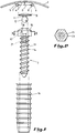
- Figure 1 shows an elevational side view, exploded, of an embodiment according to the invention.
- FIG. 2 represents a sectional view, along line II-II, of FIG. 1.
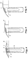
- Figures 3 to 5 show a joint cover according to the invention used to hide three differences in level.
- joint covers according to the invention can be used to mask a joint between surfaces other than floor surfaces, for example wall surfaces.
- a joint cover 1 comprising an elongated profile 2 and fixing means 3.
- the profile 2 has a first surface, which in the illustrated case is the upper surface, and a second surface, here the lower surface 4.
- Two parallel longitudinal ribs 5, 6 protrude downward from this lower surface 4 and flanges 7, 8 extend towards each other from each longitudinal rib 5, 6, forming between them a predetermined width interval D.
- a longitudinal groove 9 is thus defined between the lower surface 4 of the profile, the longitudinal ribs 5, 6 and the flanges 7, 8, and it has an opening downwards along the width interval D. This groove is accessible also by end openings at the longitudinal ends, not shown, of the elongated profile.
- the means 3 for fixing the profile 2 to the ground each comprise a head 10, having a width greater than that of the abovementioned interval. It is housed in the groove 9 of the profile 2 when the profile is in the fixing position (see Figures 3 to 5).
- the shape of the head is advantageously adapted to that of the throat to obtain a soft friction between them, which allows both an easy sliding of the head in the throat, but also its holding in place when one stops sliding it .
- this head 10 is an independent part which can be introduced separately into the longitudinal groove 9 of the profile 2. It is provided with a rod 11 which, at one end, has a ball joint 12, which has, in the illustrated example, the shape of a sphere.
- the fixing means 3 also each comprise a body anchible to the ground.
- the body comprises an anchor rod with an external thread 14 and a hinge head 15 provided with multiple sections, in particular hexagonal. This body can thus be screwed by an appropriate common key, either directly into the ground, or into a dowel 16 previously introduced into a hole drilled in the ground.
- the body comprises, in its articulation head 15, a ball joint housing 17 open towards the outside and in which the ball joint 12 of a head 10 can be pressed in by snap-fastening.
- the housing has a circular opening 18, which in the body fixing position is oriented upwards. The diameter of this opening 18 is slightly smaller than that of the spherical ball joint 12. It follows that after snap-fastening the ball joint 12 is retained in the ball joint housing 17.
- the ball joint 12 of the head 10 and the ball joint housing 17 of the body of the fixing means 3 thus form an articulation allowing a deep inclination of the head, relative to the longitudinal axis of the body.
- the head 10 When the head 10 is inserted into the groove 9 of a joint cover, it pivots in a manner corresponding to the head.
- the joint cover must be placed to mask different inequalities between two floors 19 and 20, 20 'or 20' 'respectively.
- the difference in level between 19 and 20 is 5mm, between 19 and 20 'by 10mm and between 19 and 20' 'by 16mm.
- heads 10 in a number corresponding to the fixing means 3 used, are passed through the groove 9 of the profile 2, through one of its lateral ends.
- the heads are placed in the groove at the height of the fixing means and their ball joint 12 can then be snapped into the corresponding ball joint housing 17 by simple pressure on the joint cover.
- the joint cover automatically takes the appropriate inclination between the two ground levels. If the height of the articulation heads 15 has been incorrectly adjusted, it is still possible to disengage the joint cover, readjust the height of the articulation heads 15 by screwing and then re-engage the joint cover.
- a screwing wrench can be inserted suitable which allows to screw the body of the fastening means, even when it is in the very depressed position, as in Figure 3 for example.
- fixing means to drive in, for example nails, dowels, etc., the head of which comprises the ball joint housing.
- the ball joints have a shape different from a spherical shape, for example a cylindrical shape, and that the ball joints have an appropriate corresponding shape.
Abstract
Description
La présente invention est relative à un couvre-joint pour revêtement de surface, comprenant
- un profilé allongé comportant
- une première surface visible de l'extérieur et une deuxième surface opposée à la première,
- deux nervures longitudinales parallèles faisant saillie à partir de ladite deuxième surface,
- des rebords qui s'étendent l'un vers l'autre depuis chaque nervure longitudinale, en formant entre eux un intervalle de largeur prédéterminée,
- une gorge longitudinale qui est définie entre ladite deuxième surface du profilé, les nervures longitudinales et les rebords et qui présente une ouverture longitudinale le long dudit intervalle de largeur prédéterminée,
- des moyens de fixation du profilé à une surface, comportant chacun
- une tête, présentant une largeur supérieure à celle de l'intervalle précité, et logée dans la gorge du profilé lorsque le profilé est en position de fixation, et
- un corps ancrable à la surface, relié à la tête à travers l'ouverture longitudinale de la gorge susdite, lorsque le profilé est en position de fixation.
- an elongated profile comprising
- a first surface visible from the outside and a second surface opposite the first,
- two parallel longitudinal ribs projecting from said second surface,
- flanges which extend towards each other from each longitudinal rib, forming between them a predetermined width interval,
- a longitudinal groove which is defined between said second surface of the profile, the longitudinal ribs and the flanges and which has a longitudinal opening along said interval of predetermined width,
- means for fixing the profile to a surface, each comprising
- a head, having a width greater than that of the abovementioned interval, and housed in the groove of the profile when the profile is in the fixing position, and
- a body anchored to the surface, connected to the head through the longitudinal opening of the aforementioned groove, when the profile is in the fixing position.
On connaît déjà depuis longtemps des couvre-joint qui sont destinés à masquer le passage d'un revêtement de sol à un autre.Joint covers have been known for a long time which are intended to mask the passage from one floor covering to another.
On connaît notamment un couvre-joint décoratif présentant une masse adhésive sur sa face inférieure, cet élément devant être collé au sol (BE-A-758356). Ce type de couvre-joint présente l'inconvénient du vieillissement de la colle et d'un ancrage insuffisant de ce fait.A decorative joint cover is known in particular having an adhesive mass on its underside, this element having to be glued to the ground (BE-A-758356). This type of joint cover has the drawback of the aging of the adhesive and of an insufficient anchoring thereby.
On connaît aussi des couvre-joint à clouer ou à visser au sol. On peut citer à titre d'exemple un couvre-joint de montage très aisé (BE-A-1007798).There are also known joint covers to be nailed or screwed to the ground. An example is a very easy mounting joint cover (BE-A-1007798).
Ces couvre-joint ne sont toutefois pas prévus pour masquer le passage d'un revêtement de sol à un autre, lorsque ceux-ci présentent des différences de niveau.These joint covers are however not intended to mask the passage from one floor covering to another, when these have differences in level.
Pour résoudre ce problème particulier, diverses solutions ont été proposées.To solve this particular problem, various solutions have been proposed.
On peut citer par exemple des couvre-joint formés de deux profilés longitudinaux articulés entre eux et enserrant entre eux les deux revêtements dont le joint est à couvrir (BE-A-859782). Le profité inférieur est à coller au sol et présente les mêmes inconvénients que le couvre-joint cité précédemment.Mention may be made, for example, of joint covers formed by two longitudinal sections hinged together and enclosing between them the two coatings whose joint is to be covered (BE-A-859782). The lower profit is to stick to the ground and has the same drawbacks as the joint cover mentioned above.
On peut citer aussi des couvre-joint formés d'un profité muni de deux nervures longitudinales rigides définissant avec le fond du profité une glissière pour permettre l'introduction, par une extrémité de la glissière, de têtes de clou (EP-A-588734). Le fond du profité et la tête de clou sont agencés de manière à former entre eux une articulation. Toutefois, le profilage de la gorge de réception des têtes de clou impose des limites à l'articulation au point que la demanderesse est dans l'obligation de mettre sur le marché plusieurs profilés de couvre-joint différents selon la hauteur de l'inégalité à rattraper. Il en résulte d'énormes problèmes de stockage.Mention may also be made of joint covers formed of a profit provided with two rigid longitudinal ribs defining with the bottom of the profit a slide to allow the introduction, by one end of the slide, of nail heads (EP-A-588734 ). The bottom of the profit and the nail head are arranged so as to form a joint between them. However, the profiling of the groove for receiving the nail heads imposes limits on the articulation to the point that the plaintiff is obliged to place on the market several different joint cover profiles according to the height of the unevenness at catch up. This results in huge storage problems.
On connaît aussi des profilés de finition PROSYSTEM mis sur le marché par la firme TOMECANIC, Aubergenville, France, où des chevilles sont introduites latéralement dans une glissière longitudinale du profilé. Cette glissière est conçue pour permettre un jeu limité entre la glissière et la tête des chevilles, ce qui permet, lorsque cela est nécessaire, d'incliner légèrement le profilé par rapport à l'axe des chevilles.There are also known PROSYSTEM finishing profiles marketed by the company TOMECANIC, Aubergenville, France, where dowels are inserted laterally in a longitudinal slide of the profile. This slide is designed to allow limited play between the slide and the head of the dowels, which allows, when necessary, to slightly tilt the profile relative to the axis of the dowels.
On connaît enfin un couvre-joint de la firme CARL PRINZ GmbH & Co, Goch, Allemagne, qui est décrit dans le tirage à part de Boden, Wand, Decke, Die Spezialzeitschrift fur Bodenbeläge und Raumgestaltung 2/1993. Le profilé de celui-ci est prévu asymétrique et déformable par pliage d'un côté en fonction de la différence de niveau à rattraper.Finally, there is a joint cover from the company CARL PRINZ GmbH & Co, Goch, Germany, which is described in the separate print from Boden, Wand, Decke, Die Spezialzeitschrift fur Bodenbeläge und Raumgestaltung 2/1993. The profile thereof is provided asymmetrical and deformable by folding on one side depending on the level difference to be caught.
Tous ces couvre-joint présentent l'inconvénient majeur d'un placement difficile. Ils nécessitent tous un forage de trous alignés, puis une introduction des moyens de fixation, que ce soit des clous ou des chevilles, dans la gorge prévue sur la face inférieure du profilé du couvre-joint. Cette introduction doit se faire par les extrémités de la gorge et les chevilles sont alors disposées par glissement dans la gorge à distance l'une de l'autre d'une façon correspondant à la distance entre les trous. Il faut ensuite retourner le profilé en espérant que les chevilles ne glissent pas pendant cette opération. Ce n'est que lorsque toutes les chevilles ont leur tige simultanément dans leur trou respectif qu'une pression peut être appliquée à partir du haut sur le couvre-joint pour enfoncer les chevilles dans les trous. Il est absolument nécessaire de bien mesurer la pression appliquée tout le long du couvre-joint pour que celui-ci présente une inclinaison appropriée et uniforme. Comme on peut le constater cette manoeuvre est compliquée et demande de l'adresse de la part de l'utilisateur. En outre, elle ne permet que l'emploi de moyens de fixation à enfoncer, et elle exclut ceux à visser par exemple. Enfin, en cas de fausse manoeuvre et de mauvais placement, il est très difficile de prévoir un enlèvement du couvre-joint, sans casser ou abîmer celui-ci ou le revêtement de surface.All these joint covers have the major drawback of difficult placement. They all require a drilling of aligned holes, then an introduction of the fixing means, whether nails or dowels, in the groove provided on the underside of the profile of the joint cover. This introduction must be made by the ends of the groove and the pins are then arranged by sliding in the groove at a distance from each other in a manner corresponding to the distance between the holes. The profile must then be turned over, hoping that the pins do not slip during this operation. It is only when all the dowels have their rods simultaneously in their respective holes that pressure can be applied from the top to the joint cover to push the dowels into the holes. It is absolutely necessary to measure the pressure applied all along the joint cover so that it has an appropriate and uniform inclination. As we can see this maneuver is complicated and requires the address of the user share. In addition, it only allows the use of fixing means to be pushed in, and it excludes those to be screwed for example. Finally, in the event of a false maneuver and improper placement, it is very difficult to provide for removal of the joint cover, without breaking or damaging it or the surface coating.
Par ailleurs, la plupart de ces couvre-joint nécessitent plusieurs profilés différents selon la différence de niveau à rattraper. Par leur conception, ils ne permettent qu'une inclinaison limitée du profilé utilisé par rapport à l'axe des chevilles ou clous mis en oeuvre pour la fixation du couvre-joint.In addition, most of these joint covers require several different profiles depending on the level difference to be made up. By design, they allow only a limited inclination of the profile used relative to the axis of the dowels or nails used for fixing the joint cover.
La présente invention a pour but de résoudre ces problèmes, en mettant au point un couvre-joint aisé à monter et à démonter, et d'un type unique, c'est-à-dire convenant aussi bien pour couvrir un joint en l'absence de dénivellation qu'en présence d'une différence de niveau de l'ordre par exemple de 15 à 16 mm, ce qui est généralement admis dans cette technique comme la valeur maximale à rattraper.The object of the present invention is to solve these problems by developing a joint cover which is easy to assemble and disassemble, and of a single type, that is to say suitable both for covering a joint in absence of unevenness only in the presence of a difference in level of the order of for example 15 to 16 mm, which is generally accepted in this technique as the maximum value to be made up.
On résout ce problème, suivant l'invention, par un couvre-joint tel que cité au début, dans lequel chaque moyen de fixation comprend
- une tête précitée, séparable du corps, qui peut être introduite indépendamment dans la gorge longitudinale du profilé, la tête présentant une tige qui est pourvue à une extrémité d'une rotule et qui, lorsque la tête est logée dans la gorge, passe à travers l'ouverture longitudinale de celle-ci avec la rotule située en dehors du profilé,
- un corps précité, pourvu d'un logement de rotule ouvert vers l'extérieur, dans lequel la rotule de la tête peut être insérée par encliquetage, et
- une articulation formée par la rotule de la tête et le logement de rotule du corps, en position d'insertion de la rotule dans ce logement, cette articulation permettant une inclinaison de la tête du moyen de fixation, et respectivement du profilé, par rapport à son corps.
- a said head, separable from the body, which can be introduced independently into the longitudinal groove of the profile, the head having a rod which is provided at one end of a ball joint and which, when the head is housed in the groove, passes through the longitudinal opening of the latter with the ball joint located outside the profile,
- a aforementioned body, provided with a ball joint open towards the outside, into which the ball of the head can be inserted by snap-fastening, and
- a joint formed by the ball joint of the head and the ball joint housing of the body, in the insertion position of the ball in this housing, this articulation allowing an inclination of the head of the fixing means, and respectively of the profile, relative to its body.
Un couvre-joint de ce genre offre l'avantage de permettre une inclinaison très importante du profilé par rapport aux corps des moyens de fixation. Ceux-ci peuvent être placés au préalable de manière parfaitement ajustée. Les profilés de recouvrement sont ensuite fixés par encliquetage des rotules des têtes des moyens de fixation dans le corps de ceux-ci. Le placement et l'ajustement en hauteur du couvre-joint sont donc particulièrement aisés.A joint cover of this kind offers the advantage of allowing a very significant inclination of the profile relative to the bodies of the fixing means. These can be placed beforehand in a perfectly adjusted manner. The cover profiles are then fixed by snap-fastening the ball joints of the heads of the fixing means in the body thereof. Placing and adjusting the height of the joint cover is therefore particularly easy.
Suivant une forme de réalisation de l'invention, la rotule a une forme sphérique et le logement de rotule présente une ouverture circulaire orientée vers le profilé, qui présente un diamètre légèrement plus petit que celui de la rotule sphérique. La liberté du pivotement de la tête des moyens de fixation est ainsi particulièrement bien assurée.According to one embodiment of the invention, the ball has a spherical shape and the ball housing has a circular opening oriented towards the profile, which has a diameter slightly smaller than that of the spherical ball. Freedom of pivoting of the head of the fixing means is thus particularly well ensured.
D'autres formes de réalisation de l'invention sont indiquées dans les revendications annexées.Other embodiments of the invention are indicated in the appended claims.
D'autres détails et particularités de l'invention ressortiront de la description donnée ci-après, à titre non limitatif, et avec référence aux dessins annexés.Other details and particularities of the invention will emerge from the description given below, without implied limitation, and with reference to the attached drawings.
La figure 1 représente une vue en élévation de profil, éclatée, d'une forme de réalisation suivant l'invention.Figure 1 shows an elevational side view, exploded, of an embodiment according to the invention.
La figure 2 représente une vue en coupe, suivant la ligne II-II, de la figure 1.FIG. 2 represents a sectional view, along line II-II, of FIG. 1.
Les figures 3 à 5 représentent un couvre-joint suivant l'invention utilisé pour masquer trois différences de niveau.Figures 3 to 5 show a joint cover according to the invention used to hide three differences in level.
Sur les dessins, les éléments identiques ou analogues sont désignés par les mêmes références.In the drawings, identical or analogous elements are designated by the same references.
Dans la description qui suit, on se réfère à titre d'exemple à un couvre-joint à placer entre deux revêtements de sol. Il doit être entendu que des couvre-joint suivant l'invention peuvent servir à masquer un joint entre d'autres surfaces que des surfaces de sol, par exemple des surfaces de paroi.In the description which follows, reference is made, by way of example, to a joint cover to be placed between two floor coverings. It should be understood that joint covers according to the invention can be used to mask a joint between surfaces other than floor surfaces, for example wall surfaces.
Sur la figure 1, on a représenté un couvre-joint 1 comprenant un profilé allongé 2 et des moyens de fixation 3. La profilé 2 présente une première surface, qui dans le cas illustré est la surface supérieure, et une deuxième surface, ici la surface inférieure 4. Deux nervures longitudinales parallèles 5, 6 font saillie vers le bas à partir de cette surface inférieure 4 et des rebords 7, 8 s'étendent l'un vers l'autre depuis chaque nervure longitudinale 5, 6, en formant entre eux un intervalle de largeur D prédéterminée. Une gorge longitudinale 9 est ainsi définie entre la surface inférieure 4 du profilé, les nervures longitudinales 5, 6 et les rebords 7, 8, et elle présente une ouverture vers le bas le long de l'intervalle de largeur D. Cette gorge est accessible également par des ouvertures d'extrémité aux bouts longitudinaux, non représentés, du profilé allongé.In Figure 1, there is shown a joint cover 1 comprising an
Les moyens de fixation 3 du profilé 2 au sol comportent chacun une tête 10, présentant une largeur supérieure à celle de l'intervalle précité. Elle est logée dans la gorge 9 du profilé 2 lorsque le profilé est en position de fixation (voir figures 3 à 5). La forme de la tête est avantageusement adaptée à celle de la gorge pour obtenir un frottement doux entre elles, qui permette à la fois un coulissement aisé de la tête dans la gorge, mais aussi son maintien en place lorsqu'on arrête de la faire glisser.The
Suivant l'invention, cette tête 10 est une pièce indépendante qui peut être introduite séparément dans la gorge longitudinale 9 du profilé 2. Elle est pourvue d'une tige 11 qui, à une extrémité, présente une rotule 12, laquelle a, dans l'exemple illustré, la forme d'une sphère.According to the invention, this
Ainsi qu'il ressort des figures 3 à 5, lorsque la tête 10 est logée dans la gorge 9, sa tige 11 passe à travers l'ouverture longitudinale de la gorge 9, avec la rotule 12 située en dehors du profilé 2.As is apparent from FIGS. 3 to 5, when the
Les moyens de fixation 3 suivant l'invention comprennent également chacun un corps ancrable au sol. Dans l'exemple de réalisation illustré le corps comprend une tige d'ancrage à filet externe 14 et une tête d'articulation 15 pourvue de pans multiples, notamment hexagonale. Ce corps peut ainsi être vissé par une clé courante appropriée, soit directement dans le sol, soit dans une cheville 16 préalablement introduite dans un trou foré dans le sol.The fixing means 3 according to the invention also each comprise a body anchible to the ground. In the exemplary embodiment illustrated, the body comprises an anchor rod with an
Le corps comporte, dans sa tête d'articulation 15, un logement de rotule 17 ouvert vers l'extérieur et dans lequel la rotule 12 d'une tête 10 peut être enfoncée par encliquetage. Dans l'exemple de réalisation illustré, le logement présente une ouverture circulaire 18, qui en position de fixation du corps est orientée vers le haut. Le diamètre de cette ouverture 18 est légèrement plus petit que celui de la rotule sphérique 12. Il en résulte qu'après encliquetage la rotule 12 est retenue dans le logement de rotule 17.The body comprises, in its
La rotule 12 de la tête 10 et le logement de rotule 17 du corps du moyen de fixation 3 forment ainsi une articulation permettant une profonde inclinaison de la tête, par rapport à l'axe longitudinal du corps. Lorsque la tête 10 est insérée dans la gorge 9 d'un couvre-joint, celui-ci pivote d'une manière correspondant à la tête.The ball joint 12 of the
Sur les figures 3 à 5, le couvre-joint doit être placé pour masquer des inégalités différentes entre deux sols 19 et 20, 20' ou respectivement 20''. La différence de niveau entre 19 et 20 est de 5mm, entre 19 et 20' de 10 mm et entre 19 et 20'' de 16 mm.In Figures 3 to 5, the joint cover must be placed to mask different inequalities between two
On fore tout d'abord, d'une manière connue, une série de trous alignés dans le sol 19. Puis dans chacun des trous, on enfonce une cheville 16. Dans la cavité de chaque cheville on visse alors un corps à tige filetée 13. Selon les cas on vissera plus ou moins profondément celle-ci dans le sol, d'une manière finement ajustable et aisément déterminable puisqu'on peut voir ce que l'on fait.First of all, in a known manner, a series of holes aligned in the ground are drilled 19. Then in each of the holes, a dowel is driven in. In the cavity of each dowel, a body with a threaded rod is then screwed 13 Depending on the case, we will screw it more or less deeply into the ground, in a finely adjustable and easily determinable way since we can see what we are doing.
Ensuite des têtes 10, en un nombre correspondant aux moyens de fixation 3 utilisés, sont passées dans la gorge 9 du profilé 2, par une de ses extrémités latérales. Les têtes sont placées dans la gorge à hauteur des moyens de fixation et leur rotule 12 peut alors être encliquetée dans le logement de rotule 17 correspondant par simple pression sur le couvre-joint. Grâce à l'articulation des moyens de fixation 3, le couvre-joint prend automatiquement l'inclinaison appropriée entre les deux niveaux de sol. Si la hauteur des têtes d'articulation 15 a été mal ajustée, on peut encore désencliqueter le couvre-joint, réajuster la hauteur des têtes d'articulation 15 par vissage et réencliqueter ensuite le couvre-joint.Then heads 10, in a number corresponding to the fixing means 3 used, are passed through the
En plus de la forme hexagonale de la tête d'articulation 15, permettant un vissage de l'extérieur des tiges filetées 13, on peut prévoir en outre, dans celles-ci, une cavité à pans multiples 21 qui communique avec l'extérieur par le logement de rotule 17. Dans cette cavité, on peut introduire une clé de vissage appropriée qui permet de visser le corps du moyen de fixation, même lorsqu'il est en position très enfoncée, comme sur la figure 3 par exemple.In addition to the hexagonal shape of the
Au lieu de moyens de fixation à visser, on peut bien entendu aussi prévoir des moyens de fixation à enfoncer, par exemple des clous, des chevilles, etc..., dont la tête comporte le logement de rotule.Instead of fastening means to be screwed, it is of course also possible to provide fixing means to drive in, for example nails, dowels, etc., the head of which comprises the ball joint housing.
On peut aussi concevoir que les rotules aient une forme différente d'une forme sphérique, par exemple une forme cylindrique, et que les logements de rotule aient une forme correspondante appropriée.It is also conceivable that the ball joints have a shape different from a spherical shape, for example a cylindrical shape, and that the ball joints have an appropriate corresponding shape.
Claims (8)
caractérisé en ce que chaque moyen de fixation (3) comprend
characterized in that each fixing means (3) comprises
Applications Claiming Priority (2)
| Application Number | Priority Date | Filing Date | Title |
|---|---|---|---|
| BE9600318A BE1010096A3 (en) | 1996-04-12 | 1996-04-12 | Cover seal for surface coating. |
| BE9600318 | 1996-04-12 |
Publications (2)
| Publication Number | Publication Date |
|---|---|
| EP0801187A1 true EP0801187A1 (en) | 1997-10-15 |
| EP0801187B1 EP0801187B1 (en) | 2001-10-24 |
Family
ID=3889670
Family Applications (1)
| Application Number | Title | Priority Date | Filing Date |
|---|---|---|---|
| EP97201002A Expired - Lifetime EP0801187B1 (en) | 1996-04-12 | 1997-04-08 | Joint covering for surface covering |
Country Status (4)
| Country | Link |
|---|---|
| EP (1) | EP0801187B1 (en) |
| AT (1) | ATE207570T1 (en) |
| BE (1) | BE1010096A3 (en) |
| DE (1) | DE69707544T2 (en) |
Cited By (6)
| Publication number | Priority date | Publication date | Assignee | Title |
|---|---|---|---|---|
| WO2000019037A1 (en) * | 1998-09-30 | 2000-04-06 | Dinac S.A. | Threshold bar with level compensation |
| EP1223268A1 (en) * | 2001-01-11 | 2002-07-17 | Proline Profil System GmbH | Skirting-board |
| WO2003042469A1 (en) | 2001-06-12 | 2003-05-22 | Pavol Matus | A fillet system for joining floorings especially parquet floorings |
| EP1403444A1 (en) * | 2002-09-24 | 2004-03-31 | Manfred Kochler | Profile system |
| WO2005049938A1 (en) * | 2003-10-24 | 2005-06-02 | Herm. Friedr. Künne Gmbh & Co. | Floor profile arrangement comprising a joint |
| GB2574407A (en) * | 2018-06-04 | 2019-12-11 | Celtic Heights Ltd | Roof or wall hole closing device |
Families Citing this family (1)
| Publication number | Priority date | Publication date | Assignee | Title |
|---|---|---|---|---|
| DE10211750B4 (en) * | 2002-03-18 | 2007-01-04 | Richard Malcher | profile system |
Citations (4)
| Publication number | Priority date | Publication date | Assignee | Title |
|---|---|---|---|---|
| US2996751A (en) * | 1958-09-09 | 1961-08-22 | Stanley Works | Snap-on molding |
| BE859782A (en) * | 1976-10-15 | 1978-04-14 | Dinac Sa | JUNCTION PROFILES OF COATINGS |
| EP0588734A1 (en) * | 1992-09-16 | 1994-03-23 | Dinac Profinition S.A. | Easily mounted sill member |
| BE1007798A6 (en) * | 1995-06-01 | 1995-10-24 | Vanroy Guillaume Werkhuizen | Cover seal for flooring and method for its implementation. |
-
1996
- 1996-04-12 BE BE9600318A patent/BE1010096A3/en not_active IP Right Cessation
-
1997
- 1997-04-08 EP EP97201002A patent/EP0801187B1/en not_active Expired - Lifetime
- 1997-04-08 DE DE69707544T patent/DE69707544T2/en not_active Expired - Lifetime
- 1997-04-08 AT AT97201002T patent/ATE207570T1/en not_active IP Right Cessation
Patent Citations (4)
| Publication number | Priority date | Publication date | Assignee | Title |
|---|---|---|---|---|
| US2996751A (en) * | 1958-09-09 | 1961-08-22 | Stanley Works | Snap-on molding |
| BE859782A (en) * | 1976-10-15 | 1978-04-14 | Dinac Sa | JUNCTION PROFILES OF COATINGS |
| EP0588734A1 (en) * | 1992-09-16 | 1994-03-23 | Dinac Profinition S.A. | Easily mounted sill member |
| BE1007798A6 (en) * | 1995-06-01 | 1995-10-24 | Vanroy Guillaume Werkhuizen | Cover seal for flooring and method for its implementation. |
Cited By (14)
| Publication number | Priority date | Publication date | Assignee | Title |
|---|---|---|---|---|
| WO2000019037A1 (en) * | 1998-09-30 | 2000-04-06 | Dinac S.A. | Threshold bar with level compensation |
| EP1223268A1 (en) * | 2001-01-11 | 2002-07-17 | Proline Profil System GmbH | Skirting-board |
| US6647680B2 (en) | 2001-01-11 | 2003-11-18 | Proline Profil System Gmbh | Bottom rail |
| WO2003042469A1 (en) | 2001-06-12 | 2003-05-22 | Pavol Matus | A fillet system for joining floorings especially parquet floorings |
| EP1403444A1 (en) * | 2002-09-24 | 2004-03-31 | Manfred Kochler | Profile system |
| JP2007509260A (en) * | 2003-10-24 | 2007-04-12 | ヘルム.フリードル.キューネ ゲーエムベーハー ウント コンパニー | Floor side alignment device with joints |
| WO2005049938A1 (en) * | 2003-10-24 | 2005-06-02 | Herm. Friedr. Künne Gmbh & Co. | Floor profile arrangement comprising a joint |
| CN100443686C (en) * | 2003-10-24 | 2008-12-17 | 海尔姆·福里德尔·居纳有限公司 | Floor profile arrangement comprising a joint |
| EP2050898A1 (en) * | 2003-10-24 | 2009-04-22 | Herm. Friedr. Künne GmbH & Co. | Floor profile assembly with joint |
| US7797900B2 (en) | 2003-10-24 | 2010-09-21 | Herm. Friedr. Künne Gmbh & Co. | Floor profile arrangement for bridging a joint |
| CN101446130B (en) * | 2003-10-24 | 2011-06-15 | 海尔姆.福里德尔.居纳有限公司 | Floor profile assembly |
| US8074407B2 (en) | 2003-10-24 | 2011-12-13 | Herm. Friedr. Künne Gmbh & Co. | Floor profile arrangement with articulation |
| GB2574407A (en) * | 2018-06-04 | 2019-12-11 | Celtic Heights Ltd | Roof or wall hole closing device |
| GB2574407B (en) * | 2018-06-04 | 2020-11-11 | Celtic Heights Ltd | Roof or wall hole closing anchor |
Also Published As
| Publication number | Publication date |
|---|---|
| ATE207570T1 (en) | 2001-11-15 |
| BE1010096A3 (en) | 1997-12-02 |
| DE69707544D1 (en) | 2001-11-29 |
| DE69707544T2 (en) | 2002-05-23 |
| EP0801187B1 (en) | 2001-10-24 |
Similar Documents
| Publication | Publication Date | Title |
|---|---|---|
| EP0161980B1 (en) | Make-up assembly, in particular for eye-lashes, for the use of a predetermined amount of make-up product | |
| CA2064666C (en) | Apparatus for the diffusion of a liquid product, namely a capillary product, in droplets | |
| EP2935037B1 (en) | Retractable cover system and device with such a system for storing and applying a product. | |
| FR2866819A1 (en) | TYPICALLY HEADABLE DISPENSER-APPLICATOR | |
| BE1010096A3 (en) | Cover seal for surface coating. | |
| EP0422382A1 (en) | Device to oppose backward gliding for cross-country skiing | |
| EP0164479B1 (en) | Connecting assembly for joining two profile members together | |
| CA1270267A (en) | Lateral ski boot guidance device, and cross-country boot and ski adapted to said device | |
| FR2658053A1 (en) | LIQUID APPLICATOR, FOR EXAMPLE LIQUID FOR HAIR DYEING. | |
| CA2353315A1 (en) | Device for containing and dispensing a product, specifically a hair preparation | |
| FR2756334A1 (en) | Fastening device e.g. for hook of vehicle sun visor | |
| FR2688411A1 (en) | DEVICE FOR ASSEMBLING AN ACCESSORY ON A SKI. | |
| WO1991015409A1 (en) | Device for automatic delivery of any product or object | |
| CH638685A5 (en) | ASSEMBLY COMPRISING A CROSS-COUNTRY OR WALKING SKI BOOT AND A SKI PROVIDED WITH SKI BOOT MOUNTS. | |
| FR2492015A1 (en) | U=clip for fixing to edge of perforated plate - has tubular shank and is centred by conical boss on inner leg face | |
| EP0770363B1 (en) | Implantable supporting system for dental prosthesis | |
| EP1212146B1 (en) | Device for painting with applying element controlled in rotation | |
| CA2142791C (en) | Telescoping fastening system for toilets | |
| EP0559989B1 (en) | Fixation element for a light emitting button of different thicknesses | |
| FR2599096A3 (en) | Joint for assembling horizontal and vertical section elements | |
| FR2819732A1 (en) | IMPROVEMENT FOR SNOWSHOES AND ITS RETAINING DEVICE FOR A FOOTWEAR AND ASSOCIATED FOOTWEAR | |
| FR2520817A1 (en) | Locking key for space frames - has cam operated jaw with return spring and U=shaped fixed jaw | |
| EP1396647A1 (en) | Snap-fit twist-lock device | |
| FR3121698A1 (en) | Leveling block for the production of a concrete screed having a clamp provided with a marking part | |
| FR2807786A1 (en) | SHUTTER DEVICE FOR TUNNEL FOR ROLLER SHUTTER |
Legal Events
| Date | Code | Title | Description |
|---|---|---|---|
| PUAI | Public reference made under article 153(3) epc to a published international application that has entered the european phase |
Free format text: ORIGINAL CODE: 0009012 |
|
| AK | Designated contracting states |
Kind code of ref document: A1 Designated state(s): AT BE CH DE ES FI FR GB GR IT LI LU NL PT |
|
| 17P | Request for examination filed |
Effective date: 19970821 |
|
| GRAG | Despatch of communication of intention to grant |
Free format text: ORIGINAL CODE: EPIDOS AGRA |
|
| GRAG | Despatch of communication of intention to grant |
Free format text: ORIGINAL CODE: EPIDOS AGRA |
|
| GRAH | Despatch of communication of intention to grant a patent |
Free format text: ORIGINAL CODE: EPIDOS IGRA |
|
| 17Q | First examination report despatched |
Effective date: 20010320 |
|
| GRAH | Despatch of communication of intention to grant a patent |
Free format text: ORIGINAL CODE: EPIDOS IGRA |
|
| GRAA | (expected) grant |
Free format text: ORIGINAL CODE: 0009210 |
|
| AK | Designated contracting states |
Kind code of ref document: B1 Designated state(s): AT BE CH DE ES FI FR GB GR IT LI LU NL PT |
|
| PG25 | Lapsed in a contracting state [announced via postgrant information from national office to epo] |
Ref country code: IT Free format text: LAPSE BECAUSE OF FAILURE TO SUBMIT A TRANSLATION OF THE DESCRIPTION OR TO PAY THE FEE WITHIN THE PRESCRIBED TIME-LIMIT;WARNING: LAPSES OF ITALIAN PATENTS WITH EFFECTIVE DATE BEFORE 2007 MAY HAVE OCCURRED AT ANY TIME BEFORE 2007. THE CORRECT EFFECTIVE DATE MAY BE DIFFERENT FROM THE ONE RECORDED. Effective date: 20011024 Ref country code: GB Free format text: LAPSE BECAUSE OF FAILURE TO SUBMIT A TRANSLATION OF THE DESCRIPTION OR TO PAY THE FEE WITHIN THE PRESCRIBED TIME-LIMIT Effective date: 20011024 Ref country code: FI Free format text: LAPSE BECAUSE OF FAILURE TO SUBMIT A TRANSLATION OF THE DESCRIPTION OR TO PAY THE FEE WITHIN THE PRESCRIBED TIME-LIMIT Effective date: 20011024 Ref country code: AT Free format text: LAPSE BECAUSE OF FAILURE TO SUBMIT A TRANSLATION OF THE DESCRIPTION OR TO PAY THE FEE WITHIN THE PRESCRIBED TIME-LIMIT Effective date: 20011024 |
|
| REF | Corresponds to: |
Ref document number: 207570 Country of ref document: AT Date of ref document: 20011115 Kind code of ref document: T |
|
| REG | Reference to a national code |
Ref country code: CH Ref legal event code: EP |
|
| REF | Corresponds to: |
Ref document number: 69707544 Country of ref document: DE Date of ref document: 20011129 |
|
| PG25 | Lapsed in a contracting state [announced via postgrant information from national office to epo] |
Ref country code: PT Free format text: LAPSE BECAUSE OF FAILURE TO SUBMIT A TRANSLATION OF THE DESCRIPTION OR TO PAY THE FEE WITHIN THE PRESCRIBED TIME-LIMIT Effective date: 20020124 |
|
| PG25 | Lapsed in a contracting state [announced via postgrant information from national office to epo] |
Ref country code: GR Free format text: LAPSE BECAUSE OF FAILURE TO SUBMIT A TRANSLATION OF THE DESCRIPTION OR TO PAY THE FEE WITHIN THE PRESCRIBED TIME-LIMIT Effective date: 20020125 |
|
| PG25 | Lapsed in a contracting state [announced via postgrant information from national office to epo] |
Ref country code: LU Free format text: LAPSE BECAUSE OF NON-PAYMENT OF DUE FEES Effective date: 20020408 |
|
| GBV | Gb: ep patent (uk) treated as always having been void in accordance with gb section 77(7)/1977 [no translation filed] |
Effective date: 20011024 |
|
| PG25 | Lapsed in a contracting state [announced via postgrant information from national office to epo] |
Ref country code: LI Free format text: LAPSE BECAUSE OF NON-PAYMENT OF DUE FEES Effective date: 20020430 Ref country code: ES Free format text: LAPSE BECAUSE OF FAILURE TO SUBMIT A TRANSLATION OF THE DESCRIPTION OR TO PAY THE FEE WITHIN THE PRESCRIBED TIME-LIMIT Effective date: 20020430 Ref country code: CH Free format text: LAPSE BECAUSE OF NON-PAYMENT OF DUE FEES Effective date: 20020430 |
|
| PLBE | No opposition filed within time limit |
Free format text: ORIGINAL CODE: 0009261 |
|
| STAA | Information on the status of an ep patent application or granted ep patent |
Free format text: STATUS: NO OPPOSITION FILED WITHIN TIME LIMIT |
|
| 26N | No opposition filed | ||
| REG | Reference to a national code |
Ref country code: CH Ref legal event code: PL |
|
| PGFP | Annual fee paid to national office [announced via postgrant information from national office to epo] |
Ref country code: FR Payment date: 20100311 Year of fee payment: 14 |
|
| PGFP | Annual fee paid to national office [announced via postgrant information from national office to epo] |
Ref country code: NL Payment date: 20100225 Year of fee payment: 14 Ref country code: DE Payment date: 20100423 Year of fee payment: 14 Ref country code: BE Payment date: 20100326 Year of fee payment: 14 |
|
| BERE | Be: lapsed |
Owner name: S.A. ATELIERS GUILLAUME VANROY WERKHUIZEN N.V. *RO Effective date: 20110430 |
|
| REG | Reference to a national code |
Ref country code: DE Ref legal event code: R119 Ref document number: 69707544 Country of ref document: DE |
|
| REG | Reference to a national code |
Ref country code: DE Ref legal event code: R119 Ref document number: 69707544 Country of ref document: DE |
|
| REG | Reference to a national code |
Ref country code: NL Ref legal event code: V1 Effective date: 20111101 |
|
| REG | Reference to a national code |
Ref country code: FR Ref legal event code: ST Effective date: 20111230 |
|
| PG25 | Lapsed in a contracting state [announced via postgrant information from national office to epo] |
Ref country code: BE Free format text: LAPSE BECAUSE OF NON-PAYMENT OF DUE FEES Effective date: 20110430 Ref country code: NL Free format text: LAPSE BECAUSE OF NON-PAYMENT OF DUE FEES Effective date: 20111101 Ref country code: FR Free format text: LAPSE BECAUSE OF NON-PAYMENT OF DUE FEES Effective date: 20110502 |
|
| PG25 | Lapsed in a contracting state [announced via postgrant information from national office to epo] |
Ref country code: DE Free format text: LAPSE BECAUSE OF NON-PAYMENT OF DUE FEES Effective date: 20111031 |