EP0798612A1 - Correct brush bias polarity for single and dual ESB cleaners with triboelectric negative toners - Google Patents
Correct brush bias polarity for single and dual ESB cleaners with triboelectric negative toners Download PDFInfo
- Publication number
- EP0798612A1 EP0798612A1 EP97301668A EP97301668A EP0798612A1 EP 0798612 A1 EP0798612 A1 EP 0798612A1 EP 97301668 A EP97301668 A EP 97301668A EP 97301668 A EP97301668 A EP 97301668A EP 0798612 A1 EP0798612 A1 EP 0798612A1
- Authority
- EP
- European Patent Office
- Prior art keywords
- brush
- particles
- toner
- negative
- charged
- Prior art date
- Legal status (The legal status is an assumption and is not a legal conclusion. Google has not performed a legal analysis and makes no representation as to the accuracy of the status listed.)
- Granted
Links
- 230000009977 dual effect Effects 0.000 title abstract description 15
- 239000002245 particle Substances 0.000 claims abstract description 61
- 238000004140 cleaning Methods 0.000 claims abstract description 36
- 238000000034 method Methods 0.000 claims abstract description 8
- 239000000835 fiber Substances 0.000 claims description 17
- 108091008695 photoreceptors Proteins 0.000 abstract description 11
- 238000003384 imaging method Methods 0.000 description 24
- 238000011161 development Methods 0.000 description 15
- 238000012546 transfer Methods 0.000 description 13
- 230000001235 sensitizing effect Effects 0.000 description 8
- 239000000463 material Substances 0.000 description 7
- 239000003086 colorant Substances 0.000 description 4
- 238000002347 injection Methods 0.000 description 4
- 239000007924 injection Substances 0.000 description 4
- 239000000843 powder Substances 0.000 description 3
- 230000005684 electric field Effects 0.000 description 2
- 238000012986 modification Methods 0.000 description 2
- 230000004048 modification Effects 0.000 description 2
- 238000012545 processing Methods 0.000 description 2
- 239000000758 substrate Substances 0.000 description 2
- 230000007246 mechanism Effects 0.000 description 1
- 239000011347 resin Substances 0.000 description 1
- 229920005989 resin Polymers 0.000 description 1
- 238000011144 upstream manufacturing Methods 0.000 description 1
- 239000002699 waste material Substances 0.000 description 1
Images


Classifications
-
- G—PHYSICS
- G03—PHOTOGRAPHY; CINEMATOGRAPHY; ANALOGOUS TECHNIQUES USING WAVES OTHER THAN OPTICAL WAVES; ELECTROGRAPHY; HOLOGRAPHY
- G03G—ELECTROGRAPHY; ELECTROPHOTOGRAPHY; MAGNETOGRAPHY
- G03G21/00—Arrangements not provided for by groups G03G13/00 - G03G19/00, e.g. cleaning, elimination of residual charge
- G03G21/06—Eliminating residual charges from a reusable imaging member
-
- G—PHYSICS
- G03—PHOTOGRAPHY; CINEMATOGRAPHY; ANALOGOUS TECHNIQUES USING WAVES OTHER THAN OPTICAL WAVES; ELECTROGRAPHY; HOLOGRAPHY
- G03G—ELECTROGRAPHY; ELECTROPHOTOGRAPHY; MAGNETOGRAPHY
- G03G21/00—Arrangements not provided for by groups G03G13/00 - G03G19/00, e.g. cleaning, elimination of residual charge
- G03G21/0005—Arrangements not provided for by groups G03G13/00 - G03G19/00, e.g. cleaning, elimination of residual charge for removing solid developer or debris from the electrographic recording medium
Definitions
- This invention relates to an electrostatographic printer or copier, and more particularly concems a cleaning apparatus for removing triboelectric negative toner from an imaging surface.
- US-A-5 257 079 discloses a cleaning brush electrically biased with an alternating current for removing discharged particles from an imaging surface.
- the particles on the imaging surface are discharged by a corona generating device.
- a second cleaning device including an insulative brush, a conductive brush or a blade, located upstream of the first mentioned brush, in the direction of movement of the imaging surface. further removes redeposited particles therefrom.
- US-A-4 545 669 discloses an apparatus for simultaneously charging, exposing, and developing imaging members at low voltages which comprises a semi-transparent deflected flexible imaging member, an electronic imaging source means, a light beam deflector member, a means, containing magnets therein, a development roll means containing magnets therein, a voltage source means for sensitizing roll means, a voltage source for the development roll means, a developer supply reservoir containing conductive developer particles therein comprised of insulating toner resin particles and conductive carrier particles, a sensitizing nip situated between the flexible imaging member and the sensitizing roll, and a development nip situated between the imaging member and the development roller.
- the sensitizing roll means and development roll means move in the same direction of movement as the semi-transparent deflected flexible imaging member.
- the voltage generated by the voltage source with the sensitizing nip is of an opposite polarity of the voltage generated by the voltage source for the development roller, so that an electric field of a predetermined polarity is established between the semi-transparent deflected flexible imaging member and the sensitizing roll means.
- the electric field exerts in the sensitizing roll means and in the sensitizing nip an electrostatic force on the charged toner particles causing these particles to uniformly migrate toward the imaging member, subsequently subjecting the deflected flexible imaging member to the electronic image source whereby the electrostatic force exerted on the toner particles adjacent the light struck areas of the flexible imaging member are increased thereby causing toner particles to be deposited on the deflected flexible imaging member, toner particles being removed from the deflected flexible imaging member in areas not exposed to light by the development roll and developed in the areas exposed to light.
- apparatus for removing charged triboelectric negative particles from a moving surface comprising: a pre-clean corotron having a first bias; and first cleaning means for cleaning the charged triboelectric negative particles from the surface, the first cleaning means having a second bias different from the first bias of the pre-clean corotron.
- a method for cleaning charged triboelectric negative particles from a moving surface comprising: precleaning the particles remaining on the surface using a negatively charged corotron; and charging a first cleaning brush positively to remove the negatively charged triboelectric negative particles from the surface.
- a reproduction machine utilizes a charge retentive member or photoreceptor in the form of the photoconductive belt 10 consisting of a photoconductive or imaging surface 11 and an electrically conductive, light transmissive substrate.
- the belt 10 is mounted for movement pass charging station A, and exposure station B, developer stations C, transfer station D, fusing station E and cleaning station F.
- Belt 10 moves in the direction of arrow 16 to advance successive portions thereof sequentially through the various processing stations disposed about the path of movement thereof.
- Belt 10 is entrained about a plurality of rollers 18, 20 and 22, the former of which can be used to provide suitable tensioning of the photoreceptor belt 10.
- Motor 23 rotates roller 18 to advance belt 10 in the direction of arrow 16.
- Roller 20 is coupled to motor 23 by suitable means such as a belt drive (not shown).
- a corona device such as a scorotron, corotron or dicorotron indicated generally by the reference numeral 24, charges the belt 10 to a selectively high uniform positive or negative potential. Any suitable control, well known in the art, may be employed for controlling the corona device 24.
- the charged portions of the photoconductive surface of the belt 10 are advanced through exposure station B.
- the uniformly charged photoconductive or imaging surface 11 of belt 10 is exposed to a laser based input and/or output scanning device 25 which causes the photoconductive or imaging surface 11 to be discharged in accordance with the output from the scanning device (which is, for example, a two level Raster Output Scanner (ROS)).
- ROS Raster Output Scanner
- the belt 10 which is initially charged to a voltage, undergoes dark decay to a voltage level. When exposed at the exposure station B it is discharged to near zero or ground potential for the image area in all colors.
- a development system advances development materials into contact with the electrostatic latent images.
- the development system 30 comprises first 42, second 40, third 34 and fourth 32 developer apparatuses. (However, this number may increase or decrease depending upon the number of colors, i.e. here four colors are referred to, thus, there are four developer housings.)
- the first developer apparatus 42 comprises a housing containing a donor roll 47, a magnetic roller 48, and developer material 46.
- the second developer apparatus 40 comprises a housing containing a donor roll 43, a magnetic roller 44, and developer material 45.
- the third developer apparatus 34 comprises a housing containing a donor roll 37, a magnetic roller 38, and developer material 39.
- the fourth developer apparatus 32 comprises a housing containing a donor roll 35, a magnetic roller 36, and developer material 33.
- the magnetic rollers 36, 38, 44, and 48 develop toner onto donor rolls 35, 37, 43 and 47 respectively.
- the donor rolls 35, 37, 43, and 47 then develop the toner onto the photoconductive or imaging surface 11.
- development housings 32, 34, 40, 42, and any subsequent development housings must be scavengeless so as not to disturb the image formed by the previous development apparatus. All four housings contain developer material 33, 39, 45, 46 of selected colors. Electrical biasing is accomplished via power supply 41, electrically connected to developer apparatuses 32, 34, 40 and 42.
- Sheets of substrate or support material 58 are advanced to transfer station D from a supply tray (not shown). Sheets are fed from the tray by a sheet feeder (also not shown), and advanced to transfer station D through a corona charging device 60. After transfer, the sheet continues to move in the direction of arrow 62, to fusing station E.
- Fusing station E includes a fuser assembly, indicated generally by the reference numeral 64, which permanently affixes the transferred toner powder images to the sheets.
- fuser assembly 64 includes a heated fuser roller 66 adapted to be pressure engaged with a back-up roller 68 with the toner powder images contacting fuser roller 66. In this manner, the toner powder image is permanently affixed to the sheet.
- copy sheets After fusing, copy sheets are directed to a catch tray (not shown), or a finishing station for binding, stapling, collating, etc., and removal from the machine by the operator.
- the sheet may be advanced to a duplex tray (not shown) from which it will be returned to the processor for receiving a second side copy.
- a lead edge to trail edge reversal and an odd number of sheet inversions is generally required for presentation of the second side for copying.
- overlay information in the form of additional or second color information is desirable on the first side of the sheet, no lead edge to trail edge reversal is required.
- the return of the sheets for duplex or overlay copying may also be accomplished manually.
- Residual toner and debris remaining on photoconductive belt 10 after each copy is made may be removed at cleaning station F with a brush or other type of cleaning system 70, after the particles are charged by the pre-clean corotron 96.
- the cleaning system is supported under the photoconductive belt 10 by two backers 160 and 170.
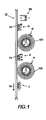
- Figure 1 shows a conventional brush bias polarity for a DESB (i.e. dual electrostatic brush) cleaner to remove residual triboelectric negative toner particles from an imaging surface.
- a negative pre-clean corotron 96 provides negative charge to the residual triboelectric negative toner particles 95 remaining on the photoconductive belt 10 (e.g. imaging surface) after transfer.
- the residual toner particle patch G carries predominantly a high negative charge after pre-clean (although a small amount of low positive charge is present).
- the triboelectric negative toner particles accept negative charge from the negative pre-clean corotron 96. This is an inherent toner characteristic that allows the triboelectric negative toner particles to have a high negative charge value in the G toner patch.
- a first cleaner brush 100 which rotates in a direction which is opposite to the direction of motion (shown by arrow 16) of the photoconductive belt 10, is positively biased to attract the predominantly negatively charged toner particles G from the photoconductive belt 10.
- the positively biased first cleaner brush 100 removes a substantial portion of the toner patch G that is later detoned from the brush 100.
- a small portion of the patch G is often not cleaned by the first brush 100, (i.e. a small portion passes under the brush 100 and a small amount may be redeposited from the brush 100 onto the belt 10) and remains: on the belt 10, after the first brush 100, as a toner patch H.
- the residual patch H of triboelectric toner 95 is predominantly positively charged after contact with the positively biased brush 100.
- a second cleaner brush 105 which rotates in a direction which is opposite to the direction of motion (shown by arrow 16) of the belt 10, is negatively biased. Some of patch H is removed by the second brush 105, due to the positive charge on the triboelectric negative particles 95. However, residual toner patch I remains after the second brush cleaner 105 because of the inherent negativity of the triboelectric particles 95 which accept negative charge from the negatively biased second brush 105. This creates highly charged negative particles, which the second negatively biased brush cannot clean. Hence, this conventional cleaning system does not clean the imaging surface of residual particles that are triboelectrically negative.
- the present invention provides efficient cleaning of the triboelectrically negative toner particles that are being used with increasing frequency in printer and copier applications.
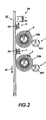
- FIG. 2 shows the preferred embodiment of the present invention using dual electrostatic cleaner brushes.
- the residual toner patch K of charged triboelectric negative toner particles 95 is negatively charged by the negative pre-clean corotron 96.
- the first brush 100 which rotates in a direction which is opposite to the direction of motion (shown by arrow 16) of the belt 10, is positively biased to remove the negatively charged residual patch K from the belt 10.
- Toner patch K is detoned from the brush 100 by a detoning roll 101. (Other means of detoning not shown include air detoning and flicker bars.)
- the toner particles not removed by the first positively biased cleaner brush 100, on the belt 10, are shown by toner patch L.
- the second brush 106 which rotates in a direction which is opposite to the direction of motion of the belt 10 (shown by arrow 16) is also positively biased.
- the second positively biased brush 106 removes the toner patch L from the photoreceptor 10.
- the toner patch L is then removed from the second brush 106 by a detoning roll 107.
- the positively charged toner patch L is removed from the belt 10 by the positively biased second brush 106 because of the following reasons: 1) the toner particles 95 are triboelectrically negative and the positive brush has an affinity for the toner, even though the particles have some positive charge; and 2) enough brush fiber strikes are sufficient to remove the toner from the photoreceptor.
- the +/+ (i.e. positive, positive) bias of the dual brush cleaner prevents the cleaning failures associated with the phenomenon of charge injection (+/- biased cleaners).
- the present invention is based upon the affinity that negative triboelectric toners have for positively biased conductive brushes, and also on providing sufficient fiber strikes for the second brush to clean the residual toner patch L.
- the reason a negatively biased second brush 105 does not clean the toner particles 95 that are not removed by the positive first brush 100 is due to the charge injection phenomenon.
- the charge injection phenomenon is explained in co-pending European patent application No. (corresponding to US patent application no. 081622,980 filed 27 March 1996, and filed concurrently herewith).
- the negatively biased brush 105 injects or transfers negative charge to the triboelectric negative toner 95.
- a negatively biased brush 105 injects negative charge into triboelectric negative toner 95, and a positively biased brush 100 does not inject charge into negative triboelectric toner 95.
- any triboelectric negative toner 95 reaching the second negatively biased brush 105 is charged more negative (see patch I) and is repelled rather then attracted to (i.e. cleaned by) the negatively biased brush 105.
- a positively biased brush can clean positively charged triboelectric toner.
- Laboratory experimentation showed that dual positive cleaner brushes 100 and 106, as shown in Figure 2, clean toner charges in the Q/D range from about -1.7 to +0.45 fC/ ⁇ m (where Q is the charge of the particle, D is the diameter of a particle and the height of a distribution represents the number of particles that have a charge Q/D). And, additionally, after transfer the positive toner Q/D does not exceed about +0.5 fC/ ⁇ m. The reason that positive Q/D values greater than 0.5 fC/ ⁇ m are not found is because the triboelectric negative toner does not readily accept positive charge. The triboelectric negative toner prefers to remain negative or become even more negative.
- the positive charge on the triboelectric negative toner does not have a high positive value, and cleaning this toner is feasible with a positive brush with sufficient fiber strikes.
- the transfer toner charge distribution is shifted more negative making the toner charge more ideal for attraction to- the dual positively charged (i.e. +, +) cleaner brushes.
- the positive Q/D value is about 0.2 fC/ ⁇ m.
- a high negative charge value, after a negative pre-clean has a Q/D of about -1.5 fC/ ⁇ m.
- FIG. 3 shows an alternate embodiment of the present invention using a single positively biased cleaner brush.
- a single positively biased brush 100 rather than a dual ESB, can be used to clean the negative triboelectric toner particles 95, shown in patch J, remaining on the surface of the belt 10 after transfer.
- more brush fiber strikes are required to clean the photoreceptor 10.
- Approximately eighteen fiber strikes are required with a single positively biased brush 100 for efficient cleaning.
- a dual brush cleaner system as shown in
- the patch of toner particles J are negatively charged by the negatively biased pre-clean corotron 96.
- the positively biased cleaner brush 100 efficiently cleans the toner patch J from the surface because the rotational speed (rpm) of the brush 100 or weave density is increased so that the number of fiber strikes for the single brush equal approximately the fiber strikes for the dual brush cleaner.
- a detoning roll 101 (or other detoning device) removes the toner patch J from the brush 100.
- the detoned toner patch is augered or directed toward a waste container (not shown).
- the present invention in the preferred embodiment of the dual brush cleaner, utilizes several inherent properties of triboelectric negative toners.
- negative triboelectric toner has a strong affinity for accepting negative charge.
- the residual toner after transfer is charged negatively with a negative pre-clean corotron.
- This creates a negative toner charge distribution that is essentially all negative and makes cleaning performance of the first brush nearly 100%.
- triboelectric negative toner does not accept positive charge.
- the Q/D value for positive toner is low. Since the cleaning efficiency of the first brush is high, and the toner mass density after the first brush is low, the positive Q/D for this toner is low. Therefore, the fiber strikes required for the second brush are selected to clean this toner after the first brush.
Landscapes
- Physics & Mathematics (AREA)
- General Physics & Mathematics (AREA)
- Cleaning In Electrography (AREA)
Abstract
Description
- This invention relates to an electrostatographic printer or copier, and more particularly concems a cleaning apparatus for removing triboelectric negative toner from an imaging surface.
- With greater use of triboelectrically negative toner in printer and copier machines, a more efficient way to remove these toner particles from the imaging surface is needed.
- US-A-5 257 079 discloses a cleaning brush electrically biased with an alternating current for removing discharged particles from an imaging surface. The particles on the imaging surface are discharged by a corona generating device. A second cleaning device including an insulative brush, a conductive brush or a blade, located upstream of the first mentioned brush, in the direction of movement of the imaging surface. further removes redeposited particles therefrom.
- US-A-4 545 669 discloses an apparatus for simultaneously charging, exposing, and developing imaging members at low voltages which comprises a semi-transparent deflected flexible imaging member, an electronic imaging source means, a light beam deflector member, a means, containing magnets therein, a development roll means containing magnets therein, a voltage source means for sensitizing roll means, a voltage source for the development roll means, a developer supply reservoir containing conductive developer particles therein comprised of insulating toner resin particles and conductive carrier particles, a sensitizing nip situated between the flexible imaging member and the sensitizing roll, and a development nip situated between the imaging member and the development roller. The sensitizing roll means and development roll means move in the same direction of movement as the semi-transparent deflected flexible imaging member. The voltage generated by the voltage source with the sensitizing nip is of an opposite polarity of the voltage generated by the voltage source for the development roller, so that an electric field of a predetermined polarity is established between the semi-transparent deflected flexible imaging member and the sensitizing roll means. The electric field exerts in the sensitizing roll means and in the sensitizing nip an electrostatic force on the charged toner particles causing these particles to uniformly migrate toward the imaging member, subsequently subjecting the deflected flexible imaging member to the electronic image source whereby the electrostatic force exerted on the toner particles adjacent the light struck areas of the flexible imaging member are increased thereby causing toner particles to be deposited on the deflected flexible imaging member, toner particles being removed from the deflected flexible imaging member in areas not exposed to light by the development roll and developed in the areas exposed to light.
- Briefly stated, and in accordance with one aspect of the present invention, there is provided apparatus for removing charged triboelectric negative particles from a moving surface, the apparatus comprising: a pre-clean corotron having a first bias; and first cleaning means for cleaning the charged triboelectric negative particles from the surface, the first cleaning means having a second bias different from the first bias of the pre-clean corotron.
- Pursuant to another aspect of the present invention, there is provided a method for cleaning charged triboelectric negative particles from a moving surface, the method comprising: precleaning the particles remaining on the surface using a negatively charged corotron; and charging a first cleaning brush positively to remove the negatively charged triboelectric negative particles from the surface.
- Other features of the present invention will become apparent by way of example only, from the following description and reference to the accompanying drawings, in which:
- Figure 1 is a schematic illustration of a conventional cleaner brush;
- Figure 2 is a schematic illustration of a preferred embodiment of a cleaner brush in accordance with the present invention;
- Figure 3 is a schematic illustration of another embodiment of a cleaner brush in accordance with the present invention which uses a single positively biased brush; and
- Figure 4 is a schematic illustration of a printing apparatus incorporating a cleaner brush in accordance with the present invention.
- For a general understanding of a color electrostatographic printing or copying machine in which the present invention may be incorporated, reference is made to US-A-4 599 285 and US-A-4 679 929, which describe the image on image process having multi-pass development with single pass transfer. Although the cleaning method and apparatus of the present invention is particularly well adapted for use in a color electrostatographic printing or copying machine, it will become evident from the following discussion, that it is equally well suited for use in a wide variety of devices and is not necessarily limited to the particular embodiments described and shown herein.
- Referring now to the drawings, which are for the purpose of describing a preferred embodiment of the invention and not for limiting same, the various processing stations employed in the reproduction machine illustrated in Figure 4 will be briefly described.
- A reproduction machine, from which the present invention finds advantageous use, utilizes a charge retentive member or photoreceptor in the form of the
photoconductive belt 10 consisting of a photoconductive orimaging surface 11 and an electrically conductive, light transmissive substrate. Thebelt 10 is mounted for movement pass charging station A, and exposure station B, developer stations C, transfer station D, fusing station E and cleaning station F. Belt 10 moves in the direction ofarrow 16 to advance successive portions thereof sequentially through the various processing stations disposed about the path of movement thereof.Belt 10 is entrained about a plurality ofrollers photoreceptor belt 10.Motor 23 rotatesroller 18 to advancebelt 10 in the direction ofarrow 16.Roller 20 is coupled tomotor 23 by suitable means such as a belt drive (not shown). - As can be seen by further reference to Figure 4, initially successive portions of
belt 10 pass through charging station A. At charging station A, a corona device such as a scorotron, corotron or dicorotron indicated generally by thereference numeral 24, charges thebelt 10 to a selectively high uniform positive or negative potential. Any suitable control, well known in the art, may be employed for controlling thecorona device 24. - Next, the charged portions of the photoconductive surface of the
belt 10 are advanced through exposure station B. At exposure station B, the uniformly charged photoconductive orimaging surface 11 ofbelt 10 is exposed to a laser based input and/oroutput scanning device 25 which causes the photoconductive orimaging surface 11 to be discharged in accordance with the output from the scanning device (which is, for example, a two level Raster Output Scanner (ROS)). - The
belt 10, which is initially charged to a voltage, undergoes dark decay to a voltage level. When exposed at the exposure station B it is discharged to near zero or ground potential for the image area in all colors. - At development station C, a development system, indicated generally by the
reference numeral 30, advances development materials into contact with the electrostatic latent images. Thedevelopment system 30 comprises first 42, second 40, third 34 and fourth 32 developer apparatuses. (However, this number may increase or decrease depending upon the number of colors, i.e. here four colors are referred to, thus, there are four developer housings.) Thefirst developer apparatus 42 comprises a housing containing adonor roll 47, amagnetic roller 48, anddeveloper material 46. Thesecond developer apparatus 40 comprises a housing containing adonor roll 43, amagnetic roller 44, anddeveloper material 45. Thethird developer apparatus 34 comprises a housing containing adonor roll 37, amagnetic roller 38, anddeveloper material 39. Thefourth developer apparatus 32 comprises a housing containing adonor roll 35, amagnetic roller 36, anddeveloper material 33. Themagnetic rollers donor rolls imaging surface 11. It is noted thatdevelopment housings developer material power supply 41, electrically connected todeveloper apparatuses - Sheets of substrate or
support material 58 are advanced to transfer station D from a supply tray (not shown). Sheets are fed from the tray by a sheet feeder (also not shown), and advanced to transfer station D through acorona charging device 60. After transfer, the sheet continues to move in the direction ofarrow 62, to fusing station E. - Fusing station E includes a fuser assembly, indicated generally by the
reference numeral 64, which permanently affixes the transferred toner powder images to the sheets. Preferably,fuser assembly 64 includes a heatedfuser roller 66 adapted to be pressure engaged with a back-uproller 68 with the toner powder images contactingfuser roller 66. In this manner, the toner powder image is permanently affixed to the sheet. - After fusing, copy sheets are directed to a catch tray (not shown), or a finishing station for binding, stapling, collating, etc., and removal from the machine by the operator. Alternatively, the sheet may be advanced to a duplex tray (not shown) from which it will be returned to the processor for receiving a second side copy. A lead edge to trail edge reversal and an odd number of sheet inversions is generally required for presentation of the second side for copying. However, if overlay information in the form of additional or second color information is desirable on the first side of the sheet, no lead edge to trail edge reversal is required. Of course, the return of the sheets for duplex or overlay copying may also be accomplished manually. Residual toner and debris remaining on
photoconductive belt 10 after each copy is made, may be removed at cleaning station F with a brush or other type ofcleaning system 70, after the particles are charged by thepre-clean corotron 96. The cleaning system is supported under thephotoconductive belt 10 by twobackers - Reference is now made to Figure 1, which shows a conventional brush bias polarity for a DESB (i.e. dual electrostatic brush) cleaner to remove residual triboelectric negative toner particles from an imaging surface. A negative pre-clean
corotron 96 provides negative charge to the residual triboelectricnegative toner particles 95 remaining on the photoconductive belt 10 (e.g. imaging surface) after transfer. The residual toner particle patch G carries predominantly a high negative charge after pre-clean (although a small amount of low positive charge is present). The triboelectric negative toner particles accept negative charge from the negative pre-cleancorotron 96. This is an inherent toner characteristic that allows the triboelectric negative toner particles to have a high negative charge value in the G toner patch. Thus, afirst cleaner brush 100, which rotates in a direction which is opposite to the direction of motion (shown by arrow 16) of thephotoconductive belt 10, is positively biased to attract the predominantly negatively charged toner particles G from thephotoconductive belt 10. The positively biasedfirst cleaner brush 100 removes a substantial portion of the toner patch G that is later detoned from thebrush 100. However, a small portion of the patch G is often not cleaned by thefirst brush 100, (i.e. a small portion passes under thebrush 100 and a small amount may be redeposited from thebrush 100 onto the belt 10) and remains: on thebelt 10, after thefirst brush 100, as a toner patch H. The residual patch H oftriboelectric toner 95 is predominantly positively charged after contact with the positivelybiased brush 100. - With continuing reference to Figure 1, a
second cleaner brush 105, which rotates in a direction which is opposite to the direction of motion (shown by arrow 16) of thebelt 10, is negatively biased. Some of patch H is removed by thesecond brush 105, due to the positive charge on the triboelectricnegative particles 95. However, residual toner patch I remains after thesecond brush cleaner 105 because of the inherent negativity of thetriboelectric particles 95 which accept negative charge from the negatively biasedsecond brush 105. This creates highly charged negative particles, which the second negatively biased brush cannot clean. Hence, this conventional cleaning system does not clean the imaging surface of residual particles that are triboelectrically negative. The present invention provides efficient cleaning of the triboelectrically negative toner particles that are being used with increasing frequency in printer and copier applications. - Reference is now made to Figure 2, which shows the preferred embodiment of the present invention using dual electrostatic cleaner brushes. The residual toner patch K of charged triboelectric
negative toner particles 95 is negatively charged by thenegative pre-clean corotron 96. Thefirst brush 100, which rotates in a direction which is opposite to the direction of motion (shown by arrow 16) of thebelt 10, is positively biased to remove the negatively charged residual patch K from thebelt 10. Toner patch K is detoned from thebrush 100 by adetoning roll 101. (Other means of detoning not shown include air detoning and flicker bars.) The toner particles not removed by the first positively biasedcleaner brush 100, on thebelt 10, are shown by toner patch L. Thesecond brush 106, which rotates in a direction which is opposite to the direction of motion of the belt 10 (shown by arrow 16) is also positively biased. The second positively biasedbrush 106 removes the toner patch L from thephotoreceptor 10. The toner patch L is then removed from thesecond brush 106 by adetoning roll 107. The positively charged toner patch L is removed from thebelt 10 by the positively biasedsecond brush 106 because of the following reasons: 1) thetoner particles 95 are triboelectrically negative and the positive brush has an affinity for the toner, even though the particles have some positive charge; and 2) enough brush fiber strikes are sufficient to remove the toner from the photoreceptor. For example, it has been shown through experimentation, that a single brush with eighteen fiber strikes cleans the residual toner off a photoreceptor, after transfer, in a printer or copier. Thus, with two brushes, each brush need only have nine fiber strikes to clean the toner off the photoreceptor. The toner mass density of the residual particles that the second brush is required to clean is very light, while the mass of this toner cannot be measured, the particles can be counted. Typically, the number of particles in the L patch range from 100 to 1000 particles per mm2. Thesecond brush 106 easily cleans this light toner density. These particles have to be cleaned because the requirement for the cleaner is less than 30 particles per mm2. - In the present invention, the +/+ (i.e. positive, positive) bias of the dual brush cleaner prevents the cleaning failures associated with the phenomenon of charge injection (+/- biased cleaners). The present invention is based upon the affinity that negative triboelectric toners have for positively biased conductive brushes, and also on providing sufficient fiber strikes for the second brush to clean the residual toner patch L.
- In the present invention, it was determined experimentally that the correct brush polarity for negative
triboelectric toner 95 and anegative pre-clean corotron 96, for a dual ESB (i.e. electrostatic brush) or conductive cleaner is +/+, i.e. both brushes are positively biased. The reason that the correct polarity to use for a dual cleaner system is +/+ (i.e. both positively biased) is because in a +/- cleaner system (i.e. the first cleaner is positively biased and the second cleaner is negatively biased) will not clean when the first positive cleaner does not clean all the toner from the photoreceptor orbelt 10. (See Figure 1). - Referring again to Figure 1, the reason a negatively biased
second brush 105 does not clean thetoner particles 95 that are not removed by the positivefirst brush 100 is due to the charge injection phenomenon. (The charge injection phenomenon is explained in co-pending European patent application No. (corresponding to US patent application no. 081622,980 filed 27 March 1996, and filed concurrently herewith). The negatively biasedbrush 105 injects or transfers negative charge to the triboelectricnegative toner 95. To state this another way, due to charge injection a negatively biasedbrush 105 injects negative charge into triboelectricnegative toner 95, and a positively biasedbrush 100 does not inject charge into negativetriboelectric toner 95. Thus, any triboelectricnegative toner 95 reaching the second negatively biasedbrush 105 is charged more negative (see patch I) and is repelled rather then attracted to (i.e. cleaned by) the negatively biasedbrush 105. - However, a positively biased brush can clean positively charged triboelectric toner. Laboratory experimentation showed that dual positive cleaner brushes 100 and 106, as shown in Figure 2, clean toner charges in the Q/D range from about -1.7 to +0.45 fC/µm (where Q is the charge of the particle, D is the diameter of a particle and the height of a distribution represents the number of particles that have a charge Q/D). And, additionally, after transfer the positive toner Q/D does not exceed about +0.5 fC/µm. The reason that positive Q/D values greater than 0.5 fC/µm are not found is because the triboelectric negative toner does not readily accept positive charge. The triboelectric negative toner prefers to remain negative or become even more negative. Therefore, the positive charge on the triboelectric negative toner does not have a high positive value, and cleaning this toner is feasible with a positive brush with sufficient fiber strikes. Further note that after pre-clean, the transfer toner charge distribution is shifted more negative making the toner charge more ideal for attraction to- the dual positively charged (i.e. +, +) cleaner brushes. After the preclean treatment, the positive Q/D value is about 0.2 fC/µm. (For comparison, a high negative charge value, after a negative pre-clean, has a Q/D of about -1.5 fC/µm.)
- Reference is now made to Figure 3, which shows an alternate embodiment of the present invention using a single positively biased cleaner brush. A single positively biased
brush 100, rather than a dual ESB, can be used to clean the negativetriboelectric toner particles 95, shown in patch J, remaining on the surface of thebelt 10 after transfer. However, more brush fiber strikes are required to clean thephotoreceptor 10. Approximately eighteen fiber strikes are required with a single positively biasedbrush 100 for efficient cleaning. In a dual brush cleaner system as shown in - Figure 2, only about nine fiber strikes for each brush is required. The fiber strikes are proportional to the brush rpm and the weave density of the brush. These parameters are selected according to the cleaning application. The use of a single positively biased
brush 100, in this manner, further eliminates complicated camming mechanisms normally required for dual brush cleaners in multipass color printing operations. - With continuing reference to Figure 3, the patch of toner particles J are negatively charged by the negatively biased
pre-clean corotron 96. The positively biasedcleaner brush 100 efficiently cleans the toner patch J from the surface because the rotational speed (rpm) of thebrush 100 or weave density is increased so that the number of fiber strikes for the single brush equal approximately the fiber strikes for the dual brush cleaner. A detoning roll 101 (or other detoning device) removes the toner patch J from thebrush 100. The detoned toner patch is augered or directed toward a waste container (not shown). - In recapitulation, the present invention in the preferred embodiment of the dual brush cleaner, utilizes several inherent properties of triboelectric negative toners. First, negative triboelectric toner has a strong affinity for accepting negative charge. Thus, the residual toner after transfer is charged negatively with a negative pre-clean corotron. This creates a negative toner charge distribution that is essentially all negative and makes cleaning performance of the first brush nearly 100%. Secondly, triboelectric negative toner does not accept positive charge. Thus, the Q/D value for positive toner is low. Since the cleaning efficiency of the first brush is high, and the toner mass density after the first brush is low, the positive Q/D for this toner is low. Therefore, the fiber strikes required for the second brush are selected to clean this toner after the first brush. Usually, about nine fiber strikes are sufficient to clean the residual toner after the first brush. Finally, the negative triboelectric toner, even though this toner may be positively charged, has an affinity for the positive brush. Hence, in the alternate embodiment of this invention (i.e. the single positive brush cleaner), effective cleaning is obtained by providing sufficient fiber strikes to clean. About eighteen fiber strikes are required to clean the typical toner mass densities after transfer with a single positive brush.
- It is, therefore, apparent that there has been provided in accordance with the present invention, positive biasing of the dual electrostatic brushes with a negative pre-clean corotron for negatively charged triboeletric toner that fully satisfies the aims and advantages hereinbefore set forth. While this invention has been described in conjunction with a specific embodiment thereof, it is evident that many alternatives, modifications, and variations will be apparent to those skilled in the art. Accordingly, it is intended to embrace all such alternatives, modifications and variations that fall within the scope of the appended claims.
Claims (10)
- Apparatus for removing charged triboelectric negative particles (95) from a moving surface (10, 11), the apparatus comprising:a pre-clean corotron (96) having a first bias; andfirst cleaning means (100) for cleaning the charged triboelectric negative particles (95; K; J) from the surface (10, 11), the first cleaning means (100) having a second bias different from the first bias of the pre-clean corotron (96).
- Apparatus according to claim 1, wherein the first cleaning means (100) comprises a conductive brush.
- Apparatus according to claim 1 or 2, wherein the first bias comprises a negative charge.
- Apparatus according to claim 2, wherein the conductive brush (100) has a rotational speed enabling about eighteen fiber strikes to remove the particles (95; K; J) from the surface (10, 11).
- Apparatus according to any one of the preceding claims, further comprising second cleaning means (106) cleaning the charged triboelectric negative particles (95) from the surface (10, 11), the second cleaning means (106) being located downstream from the first cleaning means (100), in the direction of motion of the surface (10, 11) and having the second bias.
- Apparatus according to claim 5, wherein the second cleaning means (106) comprises a conductive brush.
- Apparatus according to claim 5, when dependant on claim 2, and 6, wherein the first brush (100) is positively charged for removing the charged triboelectric negative particles (95; K; J) having predominantly negative charge from the surface (10, 11) and the second brush (106) is positively charged for removing the charged triboelectric negative particles (95; L) having predominantly positive charge from the surface (10, 11).
- Apparatus according to claim 7, wherein the first brush (100) and the second brush (106) each has a rotational speed enabling about nine fiber strikes to remove the particles (95) from the surface (10,11).
- A method for cleaning charged triboelectric negative particles (95) from a moving surface (10, 11), the method comprising:precleaning the particles (95) remaining on the surface using a negatively charged corotron (96); andcharging a first cleaning brush (100) positively to remove the negatively charged triboelectric negative particles (95; K; J) from the surface (10, 11).
- A method according to claim 9, further comprising charging a second cleaning brush (106) positively to remove both the charged triboelectric negative particles (95; K; J) having negative charge and the charged triboelectric negative particles (95; L) having positive charge that remain on the surface (10, 11) after the first brush (100) contacts the surface, the second brush (106) being located downstream from the first brush (100) in a direction of motion of the surface (10, 11).
Applications Claiming Priority (2)
| Application Number | Priority Date | Filing Date | Title |
|---|---|---|---|
| US08/622,978 US5729815A (en) | 1996-03-27 | 1996-03-27 | Correct brush bias polarity for single and dual ESB cleaners with triboelectric negative toners |
| US622978 | 1996-03-27 |
Publications (2)
| Publication Number | Publication Date |
|---|---|
| EP0798612A1 true EP0798612A1 (en) | 1997-10-01 |
| EP0798612B1 EP0798612B1 (en) | 2002-08-21 |
Family
ID=24496289
Family Applications (1)
| Application Number | Title | Priority Date | Filing Date |
|---|---|---|---|
| EP97301668A Expired - Lifetime EP0798612B1 (en) | 1996-03-27 | 1997-03-12 | Correct brush bias polarity for dual ESB cleaners with triboelectric negative toners |
Country Status (7)
| Country | Link |
|---|---|
| US (1) | US5729815A (en) |
| EP (1) | EP0798612B1 (en) |
| JP (1) | JPH1010943A (en) |
| BR (1) | BR9701476A (en) |
| CA (1) | CA2192130C (en) |
| DE (1) | DE69714804T2 (en) |
| ES (1) | ES2181990T3 (en) |
Cited By (1)
| Publication number | Priority date | Publication date | Assignee | Title |
|---|---|---|---|---|
| DE102007027268A1 (en) | 2007-06-11 | 2008-12-18 | Sandler Ag | Filter medium for air and liquid filtration |
Families Citing this family (11)
| Publication number | Priority date | Publication date | Assignee | Title |
|---|---|---|---|---|
| US5864741A (en) * | 1997-04-17 | 1999-01-26 | Xerox Corporation | Single brush cleaner with collection roll and ultrasonic cleaning assist |
| US5903797A (en) * | 1997-08-15 | 1999-05-11 | Xerox Corporation | Monitoring cleaning performance to predict cleaner life |
| US6775512B2 (en) | 2002-09-23 | 2004-08-10 | Xerox Corporation | Dual electrostatic brush cleaner bias switching for multiple pass cleaning of high density toner inputs |
| JP4458909B2 (en) * | 2004-04-20 | 2010-04-28 | キヤノン株式会社 | Image forming apparatus |
| US7305194B2 (en) * | 2004-11-30 | 2007-12-04 | Xerox Corporation | Xerographic device streak failure recovery |
| US7471924B2 (en) * | 2005-07-25 | 2008-12-30 | Fuji Xerox Co., Ltd. | Cleaning unit and image forming apparatus |
| RU2435184C2 (en) | 2006-05-12 | 2011-11-27 | Марс, Инкорпорейтед | Using powder to create images on objects, belts or sheets |
| JP2009300721A (en) * | 2008-06-13 | 2009-12-24 | Konica Minolta Business Technologies Inc | Image carrier cleaning device and image forming apparatus having the same mounted thereon |
| US7907883B2 (en) * | 2008-07-18 | 2011-03-15 | Xerox Corporation | Method and apparatus for electrostatic brush cleaning in an image production device |
| JP5605679B2 (en) * | 2010-03-18 | 2014-10-15 | 株式会社リコー | Cleaning device and image forming apparatus |
| JP5589736B2 (en) * | 2010-10-06 | 2014-09-17 | 株式会社リコー | Cleaning device and image forming apparatus |
Citations (4)
| Publication number | Priority date | Publication date | Assignee | Title |
|---|---|---|---|---|
| JPS5876871A (en) * | 1981-10-31 | 1983-05-10 | Ricoh Co Ltd | Cleaning device for fur brush |
| JPS61107369A (en) * | 1984-10-31 | 1986-05-26 | Fuji Xerox Co Ltd | Electrostatic brush cleaning device |
| JPS6217782A (en) * | 1985-07-17 | 1987-01-26 | Fuji Xerox Co Ltd | Fur brush cleaning device for electrophotographic copying machine |
| EP0650104A1 (en) * | 1993-10-22 | 1995-04-26 | Xerox Corporation | Preconditioning of photoreceptor and cleaner brush |
Family Cites Families (3)
| Publication number | Priority date | Publication date | Assignee | Title |
|---|---|---|---|---|
| US4545669A (en) * | 1984-02-21 | 1985-10-08 | Xerox Corporation | Low voltage electrophotography with simultaneous photoreceptor charging, exposure and development |
| US5257079A (en) * | 1992-09-17 | 1993-10-26 | Xerox Corporation | Electrostatic brush cleaner with a secondary cleaner |
| JPH06130875A (en) * | 1992-10-22 | 1994-05-13 | Ricoh Co Ltd | Image forming device cleaning device |
-
1996
- 1996-03-27 US US08/622,978 patent/US5729815A/en not_active Expired - Fee Related
- 1996-12-05 CA CA002192130A patent/CA2192130C/en not_active Expired - Fee Related
-
1997
- 1997-03-12 ES ES97301668T patent/ES2181990T3/en not_active Expired - Lifetime
- 1997-03-12 DE DE69714804T patent/DE69714804T2/en not_active Expired - Fee Related
- 1997-03-12 EP EP97301668A patent/EP0798612B1/en not_active Expired - Lifetime
- 1997-03-19 JP JP9066135A patent/JPH1010943A/en active Pending
- 1997-03-25 BR BR9701476A patent/BR9701476A/en not_active IP Right Cessation
Patent Citations (4)
| Publication number | Priority date | Publication date | Assignee | Title |
|---|---|---|---|---|
| JPS5876871A (en) * | 1981-10-31 | 1983-05-10 | Ricoh Co Ltd | Cleaning device for fur brush |
| JPS61107369A (en) * | 1984-10-31 | 1986-05-26 | Fuji Xerox Co Ltd | Electrostatic brush cleaning device |
| JPS6217782A (en) * | 1985-07-17 | 1987-01-26 | Fuji Xerox Co Ltd | Fur brush cleaning device for electrophotographic copying machine |
| EP0650104A1 (en) * | 1993-10-22 | 1995-04-26 | Xerox Corporation | Preconditioning of photoreceptor and cleaner brush |
Non-Patent Citations (3)
| Title |
|---|
| PATENT ABSTRACTS OF JAPAN vol. 007, no. 172 (P - 213) 29 July 1983 (1983-07-29) * |
| PATENT ABSTRACTS OF JAPAN vol. 010, no. 288 (P - 502) 30 September 1986 (1986-09-30) * |
| PATENT ABSTRACTS OF JAPAN vol. 011, no. 194 (P - 588) 23 June 1987 (1987-06-23) * |
Cited By (2)
| Publication number | Priority date | Publication date | Assignee | Title |
|---|---|---|---|---|
| DE102007027268A1 (en) | 2007-06-11 | 2008-12-18 | Sandler Ag | Filter medium for air and liquid filtration |
| EP2006008A1 (en) | 2007-06-11 | 2008-12-24 | Sandler AG | Filter medium for air and liquid filtration |
Also Published As
| Publication number | Publication date |
|---|---|
| DE69714804D1 (en) | 2002-09-26 |
| CA2192130C (en) | 2001-05-29 |
| US5729815A (en) | 1998-03-17 |
| ES2181990T3 (en) | 2003-03-01 |
| CA2192130A1 (en) | 1997-09-27 |
| EP0798612B1 (en) | 2002-08-21 |
| MX9701128A (en) | 1997-09-30 |
| JPH1010943A (en) | 1998-01-16 |
| DE69714804T2 (en) | 2002-12-19 |
| BR9701476A (en) | 1998-06-30 |
Similar Documents
| Publication | Publication Date | Title |
|---|---|---|
| EP0588553B1 (en) | Cleaning apparatus | |
| EP0472401B1 (en) | Apparatus for surface cleaning in electrophotographic imaging | |
| EP0898212B1 (en) | Method and apparatus for monitoring the cleaning performance to predict cleaner life | |
| US5729815A (en) | Correct brush bias polarity for single and dual ESB cleaners with triboelectric negative toners | |
| US6775512B2 (en) | Dual electrostatic brush cleaner bias switching for multiple pass cleaning of high density toner inputs | |
| US4990958A (en) | Reload member for a single component development housing | |
| US5329344A (en) | Lubrication of a detoning roll | |
| US5652951A (en) | Detoning cycle to increase brush life and reduce emissions by removing accumulated toner | |
| EP0798610B1 (en) | Brush bias polarity for dual electrostatic brush cleaners without pre-clean corotron for triboelectric negative toners | |
| US6980765B2 (en) | Dual polarity electrostatic brush cleaner | |
| EP0872782B1 (en) | Cleaner including a vibrator device | |
| US5500969A (en) | Dual polarity commutated roll elctrostatic cleaner with acoustic transfer assist | |
| EP0147187A1 (en) | Cleaning apparatus for charge retentive surface | |
| JPH0715608B2 (en) | Method and apparatus for removing residual toner | |
| US6169872B1 (en) | Electrostatic cleaning belt brush | |
| US5381218A (en) | Conductive cleaning brush belt and detoning thereof | |
| US5539506A (en) | Edge raggedness and background removal by post development member | |
| JPH0239186A (en) | Cleaner | |
| US7382996B2 (en) | Method for operating a cleaning station | |
| US5561513A (en) | Enhanced brush detoning by rotating the detoning roll in the "with" direction | |
| US6144834A (en) | Self biasing, extended nip electrostatic cleaner | |
| JPH06214491A (en) | Removal device | |
| US7421240B2 (en) | Asymmetric AC cleaner for improved toner charge distribution in scavenging development systems | |
| MXPA97001128A (en) | Apparatus for eliminating negatively charged triboelectric particles of a surface and method for cleaning such particles | |
| MXPA97001129A (en) | Apparatus for eliminating negatively charged triboelectric particles of a surface and method for cleaning such particles |
Legal Events
| Date | Code | Title | Description |
|---|---|---|---|
| PUAI | Public reference made under article 153(3) epc to a published international application that has entered the european phase |
Free format text: ORIGINAL CODE: 0009012 |
|
| AK | Designated contracting states |
Kind code of ref document: A1 Designated state(s): DE ES FR GB IT |
|
| 17P | Request for examination filed |
Effective date: 19980401 |
|
| 17Q | First examination report despatched |
Effective date: 20010911 |
|
| GRAG | Despatch of communication of intention to grant |
Free format text: ORIGINAL CODE: EPIDOS AGRA |
|
| RTI1 | Title (correction) |
Free format text: CORRECT BRUSH BIAS POLARITY FOR DUAL ESB CLEANERS WITH TRIBOELECTRIC NEGATIVE TONERS |
|
| GRAG | Despatch of communication of intention to grant |
Free format text: ORIGINAL CODE: EPIDOS AGRA |
|
| GRAH | Despatch of communication of intention to grant a patent |
Free format text: ORIGINAL CODE: EPIDOS IGRA |
|
| GRAH | Despatch of communication of intention to grant a patent |
Free format text: ORIGINAL CODE: EPIDOS IGRA |
|
| GRAA | (expected) grant |
Free format text: ORIGINAL CODE: 0009210 |
|
| AK | Designated contracting states |
Kind code of ref document: B1 Designated state(s): DE ES FR GB IT |
|
| REG | Reference to a national code |
Ref country code: GB Ref legal event code: FG4D |
|
| REF | Corresponds to: |
Ref document number: 69714804 Country of ref document: DE Date of ref document: 20020926 |
|
| ET | Fr: translation filed | ||
| REG | Reference to a national code |
Ref country code: ES Ref legal event code: FG2A Ref document number: 2181990 Country of ref document: ES Kind code of ref document: T3 |
|
| PLBE | No opposition filed within time limit |
Free format text: ORIGINAL CODE: 0009261 |
|
| STAA | Information on the status of an ep patent application or granted ep patent |
Free format text: STATUS: NO OPPOSITION FILED WITHIN TIME LIMIT |
|
| 26N | No opposition filed |
Effective date: 20030522 |
|
| REG | Reference to a national code |
Ref country code: GB Ref legal event code: 746 Effective date: 20041130 |
|
| PGFP | Annual fee paid to national office [announced via postgrant information from national office to epo] |
Ref country code: FR Payment date: 20050308 Year of fee payment: 9 |
|
| PGFP | Annual fee paid to national office [announced via postgrant information from national office to epo] |
Ref country code: GB Payment date: 20050309 Year of fee payment: 9 |
|
| PGFP | Annual fee paid to national office [announced via postgrant information from national office to epo] |
Ref country code: DE Payment date: 20050310 Year of fee payment: 9 |
|
| REG | Reference to a national code |
Ref country code: FR Ref legal event code: D6 |
|
| PGFP | Annual fee paid to national office [announced via postgrant information from national office to epo] |
Ref country code: ES Payment date: 20050425 Year of fee payment: 9 |
|
| PG25 | Lapsed in a contracting state [announced via postgrant information from national office to epo] |
Ref country code: GB Free format text: LAPSE BECAUSE OF NON-PAYMENT OF DUE FEES Effective date: 20060312 |
|
| PG25 | Lapsed in a contracting state [announced via postgrant information from national office to epo] |
Ref country code: ES Free format text: LAPSE BECAUSE OF NON-PAYMENT OF DUE FEES Effective date: 20060313 |
|
| PGFP | Annual fee paid to national office [announced via postgrant information from national office to epo] |
Ref country code: IT Payment date: 20060331 Year of fee payment: 10 |
|
| PG25 | Lapsed in a contracting state [announced via postgrant information from national office to epo] |
Ref country code: DE Free format text: LAPSE BECAUSE OF NON-PAYMENT OF DUE FEES Effective date: 20061003 |
|
| GBPC | Gb: european patent ceased through non-payment of renewal fee |
Effective date: 20060312 |
|
| REG | Reference to a national code |
Ref country code: FR Ref legal event code: ST Effective date: 20061130 |
|
| REG | Reference to a national code |
Ref country code: ES Ref legal event code: FD2A Effective date: 20060313 |
|
| PG25 | Lapsed in a contracting state [announced via postgrant information from national office to epo] |
Ref country code: FR Free format text: LAPSE BECAUSE OF NON-PAYMENT OF DUE FEES Effective date: 20060331 |
|
| PG25 | Lapsed in a contracting state [announced via postgrant information from national office to epo] |
Ref country code: IT Free format text: LAPSE BECAUSE OF NON-PAYMENT OF DUE FEES Effective date: 20070312 |