EP0798062A2 - Element made of foamed metal - Google Patents
Element made of foamed metal Download PDFInfo
- Publication number
- EP0798062A2 EP0798062A2 EP97105225A EP97105225A EP0798062A2 EP 0798062 A2 EP0798062 A2 EP 0798062A2 EP 97105225 A EP97105225 A EP 97105225A EP 97105225 A EP97105225 A EP 97105225A EP 0798062 A2 EP0798062 A2 EP 0798062A2
- Authority
- EP
- European Patent Office
- Prior art keywords
- component
- semi
- finished product
- foamed
- contour
- Prior art date
- Legal status (The legal status is an assumption and is not a legal conclusion. Google has not performed a legal analysis and makes no representation as to the accuracy of the status listed.)
- Granted
Links
Images

Classifications
-
- B—PERFORMING OPERATIONS; TRANSPORTING
- B22—CASTING; POWDER METALLURGY
- B22F—WORKING METALLIC POWDER; MANUFACTURE OF ARTICLES FROM METALLIC POWDER; MAKING METALLIC POWDER; APPARATUS OR DEVICES SPECIALLY ADAPTED FOR METALLIC POWDER
- B22F3/00—Manufacture of workpieces or articles from metallic powder characterised by the manner of compacting or sintering; Apparatus specially adapted therefor ; Presses and furnaces
- B22F3/10—Sintering only
- B22F3/11—Making porous workpieces or articles
- B22F3/1121—Making porous workpieces or articles by using decomposable, meltable or sublimatable fillers
- B22F3/1125—Making porous workpieces or articles by using decomposable, meltable or sublimatable fillers involving a foaming process
-
- B—PERFORMING OPERATIONS; TRANSPORTING
- B22—CASTING; POWDER METALLURGY
- B22F—WORKING METALLIC POWDER; MANUFACTURE OF ARTICLES FROM METALLIC POWDER; MAKING METALLIC POWDER; APPARATUS OR DEVICES SPECIALLY ADAPTED FOR METALLIC POWDER
- B22F3/00—Manufacture of workpieces or articles from metallic powder characterised by the manner of compacting or sintering; Apparatus specially adapted therefor ; Presses and furnaces
- B22F3/10—Sintering only
- B22F3/11—Making porous workpieces or articles
- B22F3/1103—Making porous workpieces or articles with particular physical characteristics
-
- B—PERFORMING OPERATIONS; TRANSPORTING
- B22—CASTING; POWDER METALLURGY
- B22F—WORKING METALLIC POWDER; MANUFACTURE OF ARTICLES FROM METALLIC POWDER; MAKING METALLIC POWDER; APPARATUS OR DEVICES SPECIALLY ADAPTED FOR METALLIC POWDER
- B22F7/00—Manufacture of composite layers, workpieces, or articles, comprising metallic powder, by sintering the powder, with or without compacting wherein at least one part is obtained by sintering or compression
- B22F7/002—Manufacture of composite layers, workpieces, or articles, comprising metallic powder, by sintering the powder, with or without compacting wherein at least one part is obtained by sintering or compression of porous nature
- B22F7/004—Manufacture of composite layers, workpieces, or articles, comprising metallic powder, by sintering the powder, with or without compacting wherein at least one part is obtained by sintering or compression of porous nature comprising at least one non-porous part
- B22F7/006—Manufacture of composite layers, workpieces, or articles, comprising metallic powder, by sintering the powder, with or without compacting wherein at least one part is obtained by sintering or compression of porous nature comprising at least one non-porous part the porous part being obtained by foaming
-
- B—PERFORMING OPERATIONS; TRANSPORTING
- B22—CASTING; POWDER METALLURGY
- B22F—WORKING METALLIC POWDER; MANUFACTURE OF ARTICLES FROM METALLIC POWDER; MAKING METALLIC POWDER; APPARATUS OR DEVICES SPECIALLY ADAPTED FOR METALLIC POWDER
- B22F2998/00—Supplementary information concerning processes or compositions relating to powder metallurgy
-
- Y—GENERAL TAGGING OF NEW TECHNOLOGICAL DEVELOPMENTS; GENERAL TAGGING OF CROSS-SECTIONAL TECHNOLOGIES SPANNING OVER SEVERAL SECTIONS OF THE IPC; TECHNICAL SUBJECTS COVERED BY FORMER USPC CROSS-REFERENCE ART COLLECTIONS [XRACs] AND DIGESTS
- Y10—TECHNICAL SUBJECTS COVERED BY FORMER USPC
- Y10T—TECHNICAL SUBJECTS COVERED BY FORMER US CLASSIFICATION
- Y10T29/00—Metal working
- Y10T29/49—Method of mechanical manufacture
- Y10T29/49826—Assembling or joining
- Y10T29/49904—Assembling a subassembly, then assembling with a second subassembly
-
- Y—GENERAL TAGGING OF NEW TECHNOLOGICAL DEVELOPMENTS; GENERAL TAGGING OF CROSS-SECTIONAL TECHNOLOGIES SPANNING OVER SEVERAL SECTIONS OF THE IPC; TECHNICAL SUBJECTS COVERED BY FORMER USPC CROSS-REFERENCE ART COLLECTIONS [XRACs] AND DIGESTS
- Y10—TECHNICAL SUBJECTS COVERED BY FORMER USPC
- Y10T—TECHNICAL SUBJECTS COVERED BY FORMER US CLASSIFICATION
- Y10T428/00—Stock material or miscellaneous articles
- Y10T428/12—All metal or with adjacent metals
- Y10T428/12382—Defined configuration of both thickness and nonthickness surface or angle therebetween [e.g., rounded corners, etc.]
-
- Y—GENERAL TAGGING OF NEW TECHNOLOGICAL DEVELOPMENTS; GENERAL TAGGING OF CROSS-SECTIONAL TECHNOLOGIES SPANNING OVER SEVERAL SECTIONS OF THE IPC; TECHNICAL SUBJECTS COVERED BY FORMER USPC CROSS-REFERENCE ART COLLECTIONS [XRACs] AND DIGESTS
- Y10—TECHNICAL SUBJECTS COVERED BY FORMER USPC
- Y10T—TECHNICAL SUBJECTS COVERED BY FORMER US CLASSIFICATION
- Y10T428/00—Stock material or miscellaneous articles
- Y10T428/12—All metal or with adjacent metals
- Y10T428/1241—Nonplanar uniform thickness or nonlinear uniform diameter [e.g., L-shape]
-
- Y—GENERAL TAGGING OF NEW TECHNOLOGICAL DEVELOPMENTS; GENERAL TAGGING OF CROSS-SECTIONAL TECHNOLOGIES SPANNING OVER SEVERAL SECTIONS OF THE IPC; TECHNICAL SUBJECTS COVERED BY FORMER USPC CROSS-REFERENCE ART COLLECTIONS [XRACs] AND DIGESTS
- Y10—TECHNICAL SUBJECTS COVERED BY FORMER USPC
- Y10T—TECHNICAL SUBJECTS COVERED BY FORMER US CLASSIFICATION
- Y10T428/00—Stock material or miscellaneous articles
- Y10T428/12—All metal or with adjacent metals
- Y10T428/12479—Porous [e.g., foamed, spongy, cracked, etc.]
Definitions
- the invention relates to a component made of a metallic foam material according to the preamble of claim 1 or claim 2.
- the invention further relates to a method for the final shaping of a component formed from a substantially flat metallic foam material according to the preamble of claim 6 and devices for carrying out the method .
- Metallic foam materials that either contain only a foamable layer comprising metal powder and blowing agents or that contain a layer comprising foamable metal powder and blowing agents that is provided with at least one solid metal sheet as a cover layer, whereby there are metallic bonds between the solid metal sheet and the foamable layer known per se.
- DE 41 01 630 A1 shows how a foam material is formed from a metallic powder and the addition of a gas-releasing blowing agent powder, preferably a metal hydride, which is subjected to a high pressure and high temperature after mixing, which can be done, for example, by a warm Rolling process can be achieved, and then cooled, so that a foamable semi-finished product is formed.
- a gas-releasing blowing agent powder preferably a metal hydride
- DE 44 26 627 A1 describes the production of a material with a foamable layer consisting of metal powder and blowing agent, which is at least delimited by a solid metallic cover layer.
- a connection of the different layers by roll cladding is proposed, whereby a flat layer material is formed which is to be foamed after its final shaping.
- the invention has for its object to provide metallic lightweight components for a constant dimensional production, Especially in vehicle construction, to create flat foam materials of the type mentioned.
- the invention provides components with the features of claims 1 or 2 and a manufacturing method according to claim 6 for various starting materials.
- the component according to the invention solves all the essential geometric requirements that are placed on flat metallic components in body and vehicle construction.
- the formation of the transition angle between 100 ° and less than 180 ° ensures that the structure of the foamed layer in the area of the transitions is not interrupted, drawn in or thinned, so that the mechanical stability and dimensional accuracy of the component is retained over its entire area.
- a component according to the invention has a very low mass, at the same time providing high rigidity, in particular in the case of multi-layer composites, so that such components can be used both in the load-bearing area of the body and for cladding and shielding purposes.
- Integral foam can be used in particular as crash elements, the cellular structure of the foamed material giving it very good energy absorption capacity when the component is deformed. Due to the inventive design of the component, it is possible to deform it so far before it is foamed that it can be used, for example, as the inner layer of a bumper made of z. B. plastic can be used.
- Components that comprise a foamed metallic layer that is provided on one side with a solid metallic cover layer are suitable for forming very light and highly rigid components, for example a vehicle roof that does not require a stiffening substructure.
- Materials that have a foamed layer and cladding on both sides with a solid metal sheet are suitable for producing components that have a smooth-walled surface that absorbs tensile and compressive forces on both sides, for example for the rear transverse wall of a vehicle.
- the foamed layer takes on the function of the spacer and the transmission of the thrust forces.
- Such a component also has high rigidity and low mass, is suitable for absorbing high energies, for example in the event of an accident, and is also good soundproofing.
- the foamed layer usually consists of an aluminum-based metal powder with added parts - for example silicon.
- the mechanical properties of the component can be adjusted by a suitable choice of the alloy elements and proportions.
- the use of light metal alloys is also suitable for solid metal sheets.
- a component 1 according to the invention has a foamed layer 2 which comprises a metal powder and a blowing agent which have been homogeneously mixed with one another by a mixing process and then compressed under the action of pressure, for example by axial pressing or by extrusion, to form a compact, foamable semi-finished product 2 '' and has been solidified.
- the foamed layer 2 is provided on the top and bottom sides with a solid metal sheet 3, 4, which is not mandatory, however, and in particular when a component 1 according to the invention is formed as a crash element. It is also possible to connect a foamed layer 2 with only one solid metal cover layer 3 or 4 or to produce composites from several different foamed layers, possibly separated by solid metal layers, for example to create impact elements in which, depending on the impact speed and thus -energy a different number of foamed layers takes part in the deformation due to the impact.
- the connection between the layer 2 foamed at the end of the method and the solid metal sheets 3 and 4 has come about under the action of pressure in such a way that a metallic bond between the individual layers 2 ', 3 ', 4' has been reached before the forming and foaming.
- This flat composite material 6 is first cut into pieces of a suitable size, for example using a saw.
- the shape 8 used to form the composite material 6 to form the semi-finished product 7 has angles ⁇ transverse to the contact surface of the composite material 6 in a size between approximately 100 ° and 260 °, the edges being rounded, so that the composite material 6 is bent directly to avoid. As a result, the bond is retained even in the angular ranges, and the mechanical strength of the semi-finished product 7 achieved by the shaping has no specific weak points.
- the shaping can be carried out by known customary shaping measures, for example by deep drawing with and without hold-down devices, as is known in body construction, or by a one-sided shaping method, such as the fluid cell method.
- a semi-finished product 7 which contains either plane-flat or curved surface areas 7 ′′ and possibly contours 7 ′ formed therefrom and which comprises a foamable layer 2 ′ for further processing.
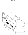
- the semifinished product 7 is inserted into a foaming mold 9, one wall 12 of which supports a side 10 of the semifinished product 7 substantially so that this side 10 must already have its final contour, since further contouring by foaming the semifinished product 7 into a component 1 no longer causes deformation of this side 10.
- the walls 12, 13 of the foaming mold 9 can be made of steel or ceramic, for example. In any case, it is important that the component 1 does not make any connection with the walls 12, 13 of the foaming mold 9, despite its internal pressure prevailing during foaming. In order to prevent any sticking together here, these walls 12, 13 can be coated.
- the thickness of the component 1 can be preselected - and thus also its density and its mechanical strength. It is thereby achieved that the same starting material can be used for components 1 with completely different properties.
- Its rigidity can also be adjusted in this way. For example, the different stiffness requirements of a short car roof or a long roof of a station wagon can be met via the degree of foaming.
- the upper wall 13 of the foaming mold can be omitted if only small demands are made on the dimensional accuracy of the foaming semi-finished product 7, such as in the formation of crash elements.
- the two opposite walls 12 and 13 of the foaming mold 9 have essentially parallel surface structures, since it is not possible to emboss further structures, for example, only into one surface 11 of the semi-finished product 7, for example through recesses in the delimiting wall 13 of the foaming mold 10th
- components 1 are obtained as lightweight series products, which can be used, for example, as body panels, as bulkheads or partition walls opposite the engine or trunk or for crash-protecting and stiffening functions within the body.
- Such components can be curved overall, for example for use as door outer panels, or comprise pronounced contours 1 'worked out from plane or curved areas 1'', which in the area of the transitions with respect to the curved or plane surface area have angles ⁇ of the order of magnitude between 100 ° and less have than 180 °, so that hereby the most diverse requirements for body panels or body panels can be fulfilled - with very light and torsion-resistant components 1.
- angles ⁇ of the same order of magnitude can occur within the pronounced contours 1 ', so that here too there is maximum flexibility and adaptability to the requirements of the body builder.
Abstract
Description
Die Erfindung bezieht sich auf ein Bauteil aus einem metallischen Schaumwerkstoff nach dem Oberbegriff von Anspruch 1 oder Anspruch 2. Die Erfindung betrifft ferner ein Verfahren zum Endformen eines aus im wesentlichen flächigem metallischem Schaumwerkstoff gebildeten Bauteils nach dem Oberbegriff des Anspruchs 6 sowie Vorrichtungen zur Ausführung des Verfahrens.The invention relates to a component made of a metallic foam material according to the preamble of
Metallische Schaumwerkstoffe, die entweder alleinig eine Metallpulver und Treibmittel umfassende aufschäumbare Schicht enthalten oder die eine aufschäumbare Metallpulver und Treibmittel umfassende Schicht enthalten, die mit zumindest einem massivmetallischen Blech als Deckschicht versehen ist, wobei zwischen dem massivmetallischen Blech und der aufschäumbaren Schicht metallische Bindungen bestehen, sind an sich bekannt.Metallic foam materials that either contain only a foamable layer comprising metal powder and blowing agents or that contain a layer comprising foamable metal powder and blowing agents that is provided with at least one solid metal sheet as a cover layer, whereby there are metallic bonds between the solid metal sheet and the foamable layer known per se.
In der DE 41 01 630 A1 ist dargestellt, wie aus einem metallischen Pulver und einer Zugabe eines gasabspaltenden Treibmittelpulvers, vorzugsweise eines Mettallhydrides, ein Schaumwerkstoff gebildet wird, der nach der Durchmischung einem hohen Druck und hoher Temperatur ausgesetzt wird, was beispielsweise durch einen Warm-Walzvorgang erreicht werden kann, und anschließend abgekühlt wird, so daß ein aufschäumbares Halbzeug entsteht.DE 41 01 630 A1 shows how a foam material is formed from a metallic powder and the addition of a gas-releasing blowing agent powder, preferably a metal hydride, which is subjected to a high pressure and high temperature after mixing, which can be done, for example, by a warm Rolling process can be achieved, and then cooled, so that a foamable semi-finished product is formed.
In der DE 44 26 627 A1 ist die Herstellung eines Werkstoffes mit einer aufschäumbaren, aus Metallpulver und Treibmittel bestehenden Schicht, die zumindest von einer massivmetallischen Deckschicht begrenzt ist, dargestellt. Für flächige Verbundwerkstoffe dieser Art wird dabei eine Verbindung der unterschiedlichen Schichten durch Walzplattieren vorgeschlagen, wodurch ein flacher Schichtwerkstoff entsteht, der nach seiner Endformung aufgeschäumt werden soll.DE 44 26 627 A1 describes the production of a material with a foamable layer consisting of metal powder and blowing agent, which is at least delimited by a solid metallic cover layer. For flat composite materials of this type, a connection of the different layers by roll cladding is proposed, whereby a flat layer material is formed which is to be foamed after its final shaping.
Die vorgestellten Verfahren zur Herstellung eines geeigneten Schaumwerkstoffes zeigen noch keine Möglichkeit, aus den zur Verfügung gestellten Werkstoffen in reproduzierbarer Weise Serienbauteile zu bilden.The methods presented for the production of a suitable foam material do not yet show any possibility of producing series components in a reproducible manner from the materials made available.
Der Erfindung liegt die Aufgabe zugrunde, metallische Leichtbauteile für eine konstant maßhaltige Serienfertigung, insbesondere im Fahrzeugbau, aus flächigen Schaumwerkstoffen der eingangs genannten Art zu schaffen.The invention has for its object to provide metallic lightweight components for a constant dimensional production, Especially in vehicle construction, to create flat foam materials of the type mentioned.
Die Erfindung sieht zur Lösung dieser Aufgabe für verschiedene Ausgangswerkstoffe Bauteile mit den Merkmalen der Ansprüche 1 oder 2 vor sowie ein Herstellungsverfahren nach Anspruch 6.To achieve this object, the invention provides components with the features of
Das erfindungsgemäße Bauteil löst alle wesentlichen geometrischen Anforderungen, die im Karosserie- und Fahrzeugbau an flächige metallische Bauteile gestellt werden. Durch die Ausbildung der Übergangswinkel zwischen 100° und weniger als 180° ist erreicht, daß die Struktur der aufgeschäumten Schicht im Bereich der Übergänge nicht unterbrochen, eingezogen oder verdünnt ist, so daß die mechanische Stabilität und Maßhaltigkeit des Bauteils über seinen gesamten Bereich erhalten bleibt.The component according to the invention solves all the essential geometric requirements that are placed on flat metallic components in body and vehicle construction. The formation of the transition angle between 100 ° and less than 180 ° ensures that the structure of the foamed layer in the area of the transitions is not interrupted, drawn in or thinned, so that the mechanical stability and dimensional accuracy of the component is retained over its entire area.
Ein erfindungsgemäßes Bauteil weist eine sehr geringe Masse auf, wobei gleichzeitig eine hohe Steifigkeit, insbesondere bei Mehrschichtverbünden, gegeben ist, so daß solche Bauteile sowohl im tragenden Bereich der Karosserie als auch zu Verkleidungs- und Abschirmzwecken eingesetzt werden können.A component according to the invention has a very low mass, at the same time providing high rigidity, in particular in the case of multi-layer composites, so that such components can be used both in the load-bearing area of the body and for cladding and shielding purposes.
Bauteile, die allein aus einer Metallpulver und Treibmittel umfassenden aufgeschäumten porösen Schicht bestehen, sog. Integralschaum, können insbesondere als Crashelemente eingesetzt werden, wobei sich durch die zellige Struktur des aufgeschäumten Werkstoffes eine sehr gute Energieabsorbtionsfähigkeit bei Verformung des Bauteiles ergibt. Durch die erfindungsgemäße Ausbildung des Bauteiles ist es möglich, dieses vor seinem Aufschäumen soweit zu verformen, daß es beispielsweise als innere Lage einer Stoßstange aus z. B. Kunststoff eingesetzt werden kann.Components that consist solely of a foamed porous layer comprising metal powder and blowing agent, so-called. Integral foam can be used in particular as crash elements, the cellular structure of the foamed material giving it very good energy absorption capacity when the component is deformed. Due to the inventive design of the component, it is possible to deform it so far before it is foamed that it can be used, for example, as the inner layer of a bumper made of z. B. plastic can be used.
Bauteile, die eine aufgeschäumte metallische Schicht umfassen, die einseitig mit einer massivmetallischen Deckschicht versehen ist, sind geeignet, sehr leichte und hochsteife Bauteile, beispielsweise ein Fahrzeugdach, das ohne eine versteifende Unterkonstruktion auskommt, zu bilden.Components that comprise a foamed metallic layer that is provided on one side with a solid metallic cover layer are suitable for forming very light and highly rigid components, for example a vehicle roof that does not require a stiffening substructure.
Werkstoffe, die eine aufgeschäumte Schicht und eine beidseitige Plattierung mit einem massivmetallischen Blech aufweisen, sind geeignet zur Herstellung von Bauteilen, die beiderseits eine glattwandige und Zug- und Druckkräfte aufnehmende Oberfläche aufweisen, beispielsweise für die hintere Querwand eines Fahrzeuges. Die aufgeschäumte Lage übernimmt dabei die Funktion des Abstandhalters sowie die Übertragung der Schubkräfte. Ein solches Bauteil weist ebenfalls eine hohe Steifigkeit bei geringer Masse auf, ist geeignet, hohe Energien - etwa bei einem Unfall - aufzunehmen und ist zudem gut schallisolierend.Materials that have a foamed layer and cladding on both sides with a solid metal sheet are suitable for producing components that have a smooth-walled surface that absorbs tensile and compressive forces on both sides, for example for the rear transverse wall of a vehicle. The foamed layer takes on the function of the spacer and the transmission of the thrust forces. Such a component also has high rigidity and low mass, is suitable for absorbing high energies, for example in the event of an accident, and is also good soundproofing.
Die aufgeschäumte Schicht besteht üblicherweise aus einem Metallpulver auf Aluminiumbasis mit zulegierten Anteilen - beispielsweise von Silizium. Durch eine geeignete Wahl der Legierungselemente und -anteile sind mechanische Eigenschaften des Bauteils einstellbar. Auch für massivmetallische Bleche bietet sich die Verwendung von Leichtmetallegierungen an.The foamed layer usually consists of an aluminum-based metal powder with added parts - for example silicon. The mechanical properties of the component can be adjusted by a suitable choice of the alloy elements and proportions. The use of light metal alloys is also suitable for solid metal sheets.
Weitere Vorteile ergeben sich aus der Zeichnung und der nachfolgenden Beschreibung des Bauteils sowie seines Herstellungsverfahrens. In der Zeichnung zeigen:
- Fig. 1
- in schematischer Ansicht schräg von oben eine Tiefziehform mit aufgelegtem zu verformendem Schaumwerkstoff,
- Fig. 2
- ein in eine Aufschäumform eingelegtes und einseitig endkonturiertes Formhalbzeug in schematischer perspektivischer Ansicht,
- Fig. 3
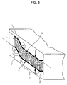
- eine ähnliche Ansicht des Bauteils am Ende des Aufschäumprozesses,
- Fig. 4
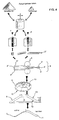
- das gesamte Herstellungsverfahren eines erfindungsgemäßen Bauteil im schematischen Überblick,
- Fig. 5
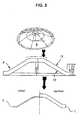
- das erfindungsgemäße Aufschäumen des Bauteils in einem schematischen Ablaufplan.
- Fig. 1
- in a schematic view obliquely from above, a deep-drawing mold with a foam material to be deformed,
- Fig. 2
- a semi-finished molded product inserted into a foaming mold and contoured on one end, in a schematic perspective view,
- Fig. 3
- a similar view of the component at the end of the foaming process,
- Fig. 4
- the entire manufacturing process of a component according to the invention in a schematic overview,
- Fig. 5
- the foaming of the component according to the invention in a schematic flow chart.
Ein erfindungsgemäßes Bauteil 1 weist eine aufgeschäumte Schicht 2 auf, die ein Metallpulver und ein Treibmittel umfaßt, die durch einen Mischungsvorgang homogen miteinander vermengt wurden und anschließend unter Druckeinwirkung, etwa durch axiales Pressen oder durch Strangpressen, zu einem kompakten, aufschäumbaren Halbzeug 2'' verdichtet und verfestigt worden ist.A
Im gezeigten Ausführungsbeispiel ist die aufgeschäumte Schicht 2 ober- und unterseitig mit jeweils einem massivmetallischen Blech 3, 4 versehen, was jedoch nicht zwingend ist und insbesondere bei Ausbildung eines erfindungsgemäßen Bauteils 1 als Crashelement verzichtbar ist. Es ist weiterhin möglich, eine aufgeschäumte Schicht 2 mit nur einer massivmetallischen Deckschicht 3 bzw. 4 zu verbinden oder auch Verbünde aus mehreren unterschiedlichen aufgeschäumten Schichten, eventuell abgetrennt durch massivmetallische Schichten, herzustellen, etwa um Aufprallelemente zu schaffen, bei denen je nach Aufprallgeschwindigkeit und damit -energie eine unterschiedliche Anzahl von aufgeschäumten Schichten an der Verformung durch den Aufprall teilnimmt.In the exemplary embodiment shown, the
Im Ausführungsbeispiel einer doppelseitig mit massivmetallischen Blechen 3 und 4 versehenen aufgeschäumten Schicht 2 ist die Verbindung zwischen der am Ende des Verfahrens aufgeschäumten Schicht 2 und den massivmetallischen Blechen 3 und 4 unter Druckeinwirkung derart zustandegekommen, daß eine metallische Bindung zwischen den einzelnen Schichten 2', 3', 4' vor der Umformung und Aufschäumung erreicht worden ist. Dazu bietet sich an, ein Walzplattieren eines Verbundes aus dem aufschäumbaren Halbzeug 2'', das nach dem Strangpressen bzw. axialen Pressen entstanden ist, und den massivmetallischen Blechen 3'',4'' zwischen zwei Walzen 5 vorzunehmen, so daß ein Verbundwerkstoff 6 mit Sandwichstruktur zweier massivmetallischer Deckschichten 3' und 4' und einer noch nicht aufgeschäumten porösen Zwischenschicht 2' entsteht.In the exemplary embodiment of a
Ein solcher im wesentlichen flächiger metallischer Verbundwerkstoff 6, der in jedem Fall eine noch aufschäumbare Schicht 2' umfaßt, weist zwischen den metallischen Blechen 3' und 4' und der aufschäumbaren Schicht 2' metallische Bindungen auf und steht nun zur weiteren Bearbeitung zur Verfügung. Dieser flächige Verbundwerkstoff 6 wird zunächst in Stücke geeigneter Größe zerteilt, beispielsweise mit Hilfe einer Säge.Such an essentially flat metallic
Ein solcher auf die gewünschten Außenmaße zurechtgeschnittener Verbundwerkstoff 6 wird nun zu einem Formhalbzeug 7 umgeformt, wobei die Umformung sowohl eine kontinuierliche Krümmung des Verbundwerkstoffes 6 bewirken kann als auch die Ausprägung einzelner Bereiche 7'.Such a
In jedem Falle weist die zur Umformung des Verbundwerkstoffes 6 zum Formhalbzeug 7 eingesetzte Form 8 quer zur Auflagefläche des Verbundwerkstoffes 6 Winkel γ in einer Größe zwischen etwa 100° und 260° auf, wobei die Kanten abgerundet sind, um somit ein direktes Abkanten des Verbundwerkstoffes 6 zu vermeiden. Dadurch bleibt der Verbund auch in den Winkelbereichen erhalten, und die mechanische Festigkeit des durch die Umformung erreichten Formhalbzeuges 7 weist keine punktuellen Schwachstellen auf.In any case, the
Das Umformen kann durch bekannte übliche Umformmaßnahmen erfolgen, etwa durch Tiefziehen mit und ohne Niederhalter, wie es im Karosseriebau bekannt ist, oder durch ein einseitiges Umformverfahren, wie etwa das Fluidzellverfahren.The shaping can be carried out by known customary shaping measures, for example by deep drawing with and without hold-down devices, as is known in body construction, or by a one-sided shaping method, such as the fluid cell method.
In jedem Falle wird ein Formhalbzeug 7 erhalten, das entweder planebene oder gekrümmte Flächenbereiche 7'' enthält und eventuell aus diesem ausgeformte Konturen 7' und das zur weiteren Bearbeitung eine aufschäumfähige Lage 2' umfaßt.In any case, a
Das Aufschäumen des Formhalbzeuges 7 zu einem Bauteil 1 in einer definierten, reproduzierbaren und maßhaltigen Weise zu gestalten ist die eigentliche Intention der Erfindung, weil dadurch erst ermöglicht wird, Bauteile für eine Serienfertigung zur Verfügung zu stellen.The foaming of the
Dazu wird das Formhalbzeug 7 in eine Aufschäumform 9 eingelegt, deren eine Wandung 12 eine Seite 10 des Formhalbzeuges 7 im wesentlichen flächendeckend abstützt, so daß diese Seite 10 bereits ihre Endkontur aufweisen muß, da eine weitere Konturgebung durch das Aufschäumen des Formhalbzeuges 7 zu einem Bauteil 1 keine Verformung dieser Seite 10 mehr mit sich bringt.For this purpose, the
Die Wandungen 12,13 der Aufschäumform 9 können beispielsweise aus Stahl oder auch aus Keramik bestehen. In jedem Fall ist wichtig, daß das Bauteil 1 trotz seines beim Aufschäumen herrschenden Innendruckes keine Verbindung mit den Wandungen 12,13 der Aufschäumform 9 eingeht. Um hier jegliches Aneinanderhaften zu unterbinden, können diese Wandungen 12,13 beschichtet sein.The
Durch die flächige Unterstützung einer endkonturierten Seite 10 des noch nicht aufgeschäumten Formhalbzeuges 7 wird beim Aufschäumen vermieden, daß diese bereits die Endkontur des späteren Bauteils 1 aufweisende Seite 10 während des Aufschäumens durch den Druck des gasabspaltenden Treibmittels in der aufschäumenden Schicht 2' nach außen hin verformt wird. Dabei ist es vorteilhaft und für manche Anwendungen zwingend, der gegenüberliegenden Seite 11 des Formhalbzeuges 7 eine weitere Wandung 13 der Aufschäumform 9 zuzuordnen, die mit festem Abstand zur Wandung 12 angeordnet ist, um dadurch das Maß der Ausdehnung der aufschäumenden Schicht 2' definiert zu begrenzen und somit eine Maßhaltigkeit des fertigen Bauteils 1 mit weniger als 5/10 mm Abweichung zu ermöglichen. Durch eine Einstellbarkeit des Abstandes der Wandungen 12 und 13 läßt sich die Dicke des Bauteils 1 vorwählen - und damit auch seine Dichte und seine mechanische Festigkeit. Dadurch ist erreicht, daß derselbe Ausgangswerkstoff für Bauteile 1 mit völlig verschiedenen Eigenschaften verwendet werden kann. Je größer der erlaubte Aufschäumweg in der Aufschäumform 9 gelassen wird, desto geringer ist die Dichte des fertigen Bauteils 1. Auch seine Steifigkeit läßt sich auf diese Weise einstellen. Damit können beispielsweise die unterschiedlichen Steifigkeitsanforderungen eines kurzen PKW-Daches bzw. eines langen Daches eines Kombis über den Grad der Aufschäumung erfüllt werden.Due to the extensive support of an end-
Die obere Wandung 13 der Aufschäumform kann entfallen, wenn an die Dickenmaßhaltigkeit des aufschäumenden Formhalbzeuges 7 nur geringe Ansprüche gestellt werden, wie beispielsweise bei der Ausbildung von Crashelementen.The
In den meisten Fällen wird es jedoch unverzichtbar sein, durch beide Wandungen 12 und 13 den Aufschäumweg und damit das Endmaß des aufgeschäumten Bauteils 1 zu begrenzen, wodurch eine Serienfertigung immer gleicher aufgeschäumter Bauteile 1 ermöglicht ist.In most cases, however, it will be indispensable, through both
Die beiden gegenüberliegenden Wandungen 12 und 13 der Aufschäumform 9 weisen dabei im wesentlichen parallele Flächenstrukturen auf, da es nicht möglich ist, durch das Aufschäumen weitere Strukturen etwa nur in eine Oberfläche 11 des Formhalbzeuges 7 einzuprägen - etwa durch Aussparungen in der begrenzenden Wand 13 der Aufschäumform 10.The two
Durch ein derart definiertes Aufschäumen werden Bauteile 1 als Leichtbauserienprodukte erhalten, die beispielsweise als Karosserieinnenbleche, als Spritzwände oder Abtrennwände gegenüber Motor- oder Kofferraum oder zur crashsichernden und aussteifenden Funktion innerhalb der Karosserie eingesetzt werden können.By means of such defined foaming,
Solche Bauteile können insgesamt gekrümmt sein, beispielsweise zur Verwendung als Türaußenbleche, oder aus planebenen oder gekrümmten Bereichen 1'' herausgearbeitete ausgeprägte Konturen 1' umfassen, die im Bereich der Übergänge gegenüber dem gekrümmten oder planebenen Flächenbereich Winkel α in der Größenordnung zwischen 100° und weniger als 180° aufweisen, so daß hiermit die verschiedensten Anforderungen an Karosseriebleche bzw. Karosserieinnenbleche erfüllt werden können - mit sehr leichten und verwindungssteifen Bauteilen 1.Such components can be curved overall, for example for use as door outer panels, or comprise pronounced contours 1 'worked out from plane or curved areas 1'', which in the area of the transitions with respect to the curved or plane surface area have angles α of the order of magnitude between 100 ° and less have than 180 °, so that hereby the most diverse requirements for body panels or body panels can be fulfilled - with very light and torsion-
Ebenso können innerhalb der ausgeprägten Konturen 1' Winkel β in der gleichen Größenordnung auftreten, so daß auch hier eine maximale Flexibilität und Anpassungsfähigkeit an die Ansprüche der Karosseriebauer gegeben ist.Likewise, angles β of the same order of magnitude can occur within the pronounced contours 1 ', so that here too there is maximum flexibility and adaptability to the requirements of the body builder.
Mit dem hier vorgestellten Verfahren und den daraus resultierenden Bauteilen ist es erstmals möglich, Werkstoffe aus metallischen Schäumen - und eventuell massivmetallischen Blechen, die mit diesen verbunden sind - zur Serienfertigung einzusetzen und in reproduzierbarer Weise durch bekannte Umformprozesse und ein anschließendes definiertes Aufschäumen der Metallpulver und Treibmittel enthaltenden Schicht 2' die Vorteile, die ein solcher Leichtbau bietet, in die Praxis umzusetzen.With the method presented here and the resulting components, it is possible for the first time to use materials made of metallic foams - and possibly solid metallic sheets that are connected to them - for series production and in a reproducible manner using known forming processes and subsequent defined foaming of the metal powder and blowing agent containing layer 2 'to implement the advantages that such a lightweight construction offers in practice.
Claims (11)
Applications Claiming Priority (2)
| Application Number | Priority Date | Filing Date | Title |
|---|---|---|---|
| DE19612781 | 1996-03-29 | ||
| DE19612781A DE19612781C1 (en) | 1996-03-29 | 1996-03-29 | Component made of metallic foam material, process for final shaping of this component and device for carrying out the process |
Publications (3)
| Publication Number | Publication Date |
|---|---|
| EP0798062A2 true EP0798062A2 (en) | 1997-10-01 |
| EP0798062A3 EP0798062A3 (en) | 1998-10-07 |
| EP0798062B1 EP0798062B1 (en) | 2001-12-19 |
Family
ID=7790011
Family Applications (1)
| Application Number | Title | Priority Date | Filing Date |
|---|---|---|---|
| EP97105225A Expired - Lifetime EP0798062B1 (en) | 1996-03-29 | 1997-03-27 | Element made of foamed metal |
Country Status (4)
| Country | Link |
|---|---|
| US (3) | US6090232A (en) |
| EP (1) | EP0798062B1 (en) |
| JP (1) | JPH1058575A (en) |
| DE (2) | DE19612781C1 (en) |
Cited By (6)
| Publication number | Priority date | Publication date | Assignee | Title |
|---|---|---|---|---|
| EP0915007A2 (en) * | 1997-11-07 | 1999-05-12 | DaimlerChrysler AG | Body structure comprising at least one transversal wall |
| DE19905124C1 (en) * | 1998-12-23 | 2000-08-03 | Mannesmann Ag | Method and device for producing a profile part |
| DE19941199A1 (en) * | 1999-08-30 | 2001-03-01 | Arved Huebler | Production of composite articles, e.g. shafts and axles, from foam component and other solid components, comprises combining sections whose foam structure and arrangement is chosen to give uniform mass distribution throughout article |
| US6573309B1 (en) | 1999-03-03 | 2003-06-03 | Henkel Teroson Gmbh | Heat-curable, thermally expandable moulded park |
| WO2003054069A1 (en) | 2001-12-21 | 2003-07-03 | Henkel Teroson Gmbh | Expandable epoxy resin-based systems modified with thermoplastic polymers |
| US8288447B2 (en) | 2006-06-07 | 2012-10-16 | Henkel Ag & Co. Kgaa | Foamable compositions based on epoxy resins and polyesters |
Families Citing this family (62)
| Publication number | Priority date | Publication date | Assignee | Title |
|---|---|---|---|---|
| DE19648164C2 (en) * | 1996-11-21 | 2000-01-27 | Karmann Gmbh W | Body part, in particular profile frame support |
| US6103341A (en) | 1997-12-08 | 2000-08-15 | L&L Products | Self-sealing partition |
| DE19800008C1 (en) * | 1998-01-02 | 1999-07-08 | Karmann Gmbh W | Process for the final shaping of a component with a layer of metallic foam material |
| DE29800005U1 (en) * | 1998-01-02 | 1999-05-06 | Karmann Gmbh W | Component, in particular body component for motor vehicles |
| NO981119L (en) * | 1998-01-14 | 1999-07-15 | Norsk Hydro As | Coachbuilding |
| DE19813554A1 (en) * | 1998-03-27 | 1999-09-30 | Vaw Ver Aluminium Werke Ag | Composite sheet or strip in sandwich structure and process for its production |
| AT408317B (en) * | 1998-04-09 | 2001-10-25 | Mepura Metallpulver | METHOD FOR PRODUCING FOAM METAL BODIES |
| DE19849600C1 (en) * | 1998-10-28 | 2001-02-22 | Schunk Sintermetalltechnik Gmb | Process for the production of a metallic composite |
| DE19852277C2 (en) * | 1998-11-13 | 2000-12-14 | Schunk Sintermetalltechnik Gmb | Process for the production of a metallic composite material and semi-finished product for such |
| DE19854175C1 (en) * | 1998-11-24 | 2000-03-23 | Fritz Michael Streuber | Metal foam process for joining components having variety of shapes involves using shell-like clamp which bounds a space and accommodates foamable metal material producing a joint in the form of compound component |
| DE19854173C2 (en) * | 1998-11-24 | 2000-11-23 | Fritz Michael Streuber | Metal foam molded body |
| DE19908867A1 (en) * | 1999-03-01 | 2000-09-07 | Arved Huebler | Composite body useful in machine construction comprises metal foam and solid parts joined together by a metallurgical bond of fused adjoining material layers |
| DE19911213C1 (en) * | 1999-03-12 | 2000-11-09 | Zf Lemfoerder Metallwaren Ag | Composite component and method for producing the composite component |
| DE19954755A1 (en) * | 1999-11-15 | 2001-05-17 | Schunk Sintermetalltechnik Gmb | Semi-finished metal product is foamed, e.g. to produce a lightweight sandwich construction material for traffic engineering, by heating in a chamber using external radiation |
| US6131897A (en) | 1999-03-16 | 2000-10-17 | L & L Products, Inc. | Structural reinforcements |
| DE19932883C1 (en) * | 1999-07-16 | 2000-10-12 | Schunk Sintermetalltechnik Gmb | Foaming of a molding made of a mixture of metal powder and a gas-splitting propellant powder comprises adjusting the walls of the foam mold so that they lie flat on the sides of the molding facing the mold during foaming |
| DE19933870C1 (en) * | 1999-07-23 | 2001-02-22 | Schunk Sintermetalltechnik Gmb | Composite body used in vehicle construction has a foamed metal material e.g. aluminum foam surrounding a reinforcement |
| US6358584B1 (en) | 1999-10-27 | 2002-03-19 | L&L Products | Tube reinforcement with deflecting wings and structural foam |
| US6481911B1 (en) | 1999-11-24 | 2002-11-19 | Fritz Michael Streuber | Jointing method for joining preformed bodies |
| US6668457B1 (en) * | 1999-12-10 | 2003-12-30 | L&L Products, Inc. | Heat-activated structural foam reinforced hydroform |
| NL1014116C2 (en) * | 2000-01-19 | 2001-07-20 | Corus Aluminium Walzprod Gmbh | Method and device for forming a laminate of compressed metal powder with a foaming agent between two metal layers, and product formed therewith. |
| US6467834B1 (en) | 2000-02-11 | 2002-10-22 | L&L Products | Structural reinforcement system for automotive vehicles |
| CA2399457C (en) * | 2000-02-11 | 2009-09-15 | L&L Products, Inc. | Structural reinforcement system for automotive vehicles |
| NO311708B1 (en) | 2000-02-25 | 2002-01-14 | Cymat Corp | Process and equipment for forming molded products |
| US6296298B1 (en) | 2000-03-14 | 2001-10-02 | L&L Products, Inc. | Structural reinforcement member for wheel well |
| US6482486B1 (en) | 2000-03-14 | 2002-11-19 | L&L Products | Heat activated reinforcing sleeve |
| US6422575B1 (en) | 2000-03-14 | 2002-07-23 | L&L Products, Inc. | Expandable pre-formed plug |
| US6321793B1 (en) | 2000-06-12 | 2001-11-27 | L&L Products | Bladder system for reinforcing a portion of a longitudinal structure |
| US6820923B1 (en) | 2000-08-03 | 2004-11-23 | L&L Products | Sound absorption system for automotive vehicles |
| US6471285B1 (en) | 2000-09-29 | 2002-10-29 | L&L Products, Inc. | Hydroform structural reinforcement system |
| US6561571B1 (en) | 2000-09-29 | 2003-05-13 | L&L Products, Inc. | Structurally enhanced attachment of a reinforcing member |
| CA2344088A1 (en) * | 2001-01-16 | 2002-07-16 | Unknown | A method and an apparatus for production of a foam metal |
| US6706239B2 (en) | 2001-02-05 | 2004-03-16 | Porvair Plc | Method of co-forming metal foam articles and the articles formed by the method thereof |
| US6852272B2 (en) * | 2001-03-07 | 2005-02-08 | Advanced Ceramics Research, Inc. | Method for preparation of metallic and ceramic foam products and products made |
| US6660224B2 (en) * | 2001-08-16 | 2003-12-09 | National Research Council Of Canada | Method of making open cell material |
| CA2456822C (en) * | 2001-08-17 | 2010-11-09 | Cymat Corp. | Method and apparatus for low pressure aluminum foam casting |
| EP1470262B1 (en) * | 2002-02-01 | 2005-10-19 | Cymat Corp. | Metal foam casting apparatus and method |
| MXPA04008600A (en) * | 2002-03-04 | 2006-02-24 | Cymat Corp | Sealed impeller for producing metal foam and system and method therefor. |
| US20040018353A1 (en) * | 2002-07-25 | 2004-01-29 | L&L Products, Inc. | Composite metal foam damping/reinforcement structure |
| DE10260419B4 (en) * | 2002-12-21 | 2009-06-18 | Wilhelm Karmann Gmbh | Components and semi-finished products with metallic foam layer |
| DE10260418A1 (en) * | 2002-12-21 | 2004-07-15 | Wilhelm Karmann Gmbh | Components and semi-finished products with a metallic foam layer |
| DE10302298A1 (en) * | 2003-01-22 | 2004-08-05 | Henkel Kgaa | Heat-curable, thermally expandable composition with a high degree of expansion |
| DE10304078A1 (en) | 2003-01-31 | 2004-08-26 | Wilhelm Karmann Gmbh | Components with a metallic foam layer |
| EP1468765A1 (en) * | 2003-04-16 | 2004-10-20 | Corus Technology BV | Preform for foamed sheet product and foamed product manufactured therefrom |
| AT412876B (en) * | 2003-08-05 | 2005-08-25 | Arc Leichtmetallkompetenzzentrum Ranshofen Gmbh | FOAMING SEMI-FINISHED AND METHOD FOR PRODUCING METAL PARTS OF INTERNAL PORO-SITY |
| US7516529B2 (en) * | 2003-12-17 | 2009-04-14 | General Motors Corporation | Method for producing in situ metallic foam components |
| US7328831B1 (en) | 2004-06-25 | 2008-02-12 | Porvair Plc | Method of making a brazed metal article and the article formed thereby |
| JP4051052B2 (en) * | 2004-07-09 | 2008-02-20 | 本田技研工業株式会社 | Vehicle hood structure |
| DE102004036873B4 (en) * | 2004-07-29 | 2007-06-28 | Wilhelm Karmann Gmbh | Method and device for component production |
| DE102004038932A1 (en) * | 2004-08-11 | 2006-02-23 | Mtu Aero Engines Gmbh | Method for connecting components |
| DE102004040888A1 (en) | 2004-08-24 | 2006-04-13 | Wilhelm Karmann Gmbh | Production of components with at least one metallic foam layer |
| DE102004054961A1 (en) * | 2004-11-13 | 2006-05-18 | Wilhelm Karmann Gmbh | Device for foaming a metal powder useful in mobile units, e.g. automobiles has a propellant including site of a metal semifinished product with one or more large metal sites above and/or below the foamed site |
| DE102005005041A1 (en) * | 2005-02-03 | 2006-08-10 | Märkisches Werk GmbH | Valve for controlling the gas exchange, in particular in internal combustion engines |
| DE202005006240U1 (en) * | 2005-04-18 | 2005-10-20 | Seeliger, Hans-Wolfgang | Metal sandwich structure to be used for creation of three-dimensional shapes, produced by heating metal foam while being compressed |
| DE102005032098B4 (en) * | 2005-07-08 | 2012-09-06 | Fraunhofer-Gesellschaft zur Förderung der angewandten Forschung e.V. | Method and apparatus for producing metal foam composite bodies and metal foam composite hollow bodies |
| US20070154731A1 (en) * | 2005-12-29 | 2007-07-05 | Serguei Vatchiants | Aluminum-based composite materials and methods of preparation thereof |
| DE102006020860B4 (en) * | 2006-05-04 | 2008-02-07 | Alulight International Gmbh | Process for the production of composite bodies and composite bodies produced therefrom |
| US9403213B2 (en) * | 2006-11-13 | 2016-08-02 | Howmedica Osteonics Corp. | Preparation of formed orthopedic articles |
| US10539041B2 (en) | 2013-10-22 | 2020-01-21 | General Electric Company | Cooled article and method of forming a cooled article |
| CN103831979B (en) * | 2014-03-11 | 2016-02-10 | 哈尔滨理工大学 | A kind of ceramic base ripple sandwich structure composite material prepare mould |
| CN104177110B (en) * | 2014-08-28 | 2016-01-20 | 哈尔滨理工大学 | The preparation method of corrugated configuration ceramic matric composite flat board |
| FR3067270B1 (en) * | 2017-06-13 | 2021-12-24 | Safran | PROCESS FOR MAKING A METALLIC PART BY DEBINDING AND SINTERING |
Citations (4)
| Publication number | Priority date | Publication date | Assignee | Title |
|---|---|---|---|---|
| EP0189674A2 (en) * | 1985-01-26 | 1986-08-06 | Imi Titanium Limited | Formation of porous bodies |
| DE4018360C1 (en) * | 1990-06-08 | 1991-05-29 | Fraunhofer-Gesellschaft Zur Foerderung Der Angewandten Forschung Ev, 8000 Muenchen, De | Porous metal body prodn. - involves compaction at low temp. followed by heating to near melting point of metal |
| DE4426627A1 (en) * | 1993-07-29 | 1995-02-02 | Fraunhofer Ges Forschung | Metallic composite material and a method for its production |
| DE4424157A1 (en) * | 1993-07-29 | 1995-02-02 | Fraunhofer Ges Forschung | Porous metallic material having anisotropic properties |
Family Cites Families (18)
| Publication number | Priority date | Publication date | Assignee | Title |
|---|---|---|---|---|
| US2974034A (en) * | 1957-12-12 | 1961-03-07 | Lor Corp | Method of foaming granulated metal |
| US2983597A (en) * | 1959-06-11 | 1961-05-09 | Lor Corp | Metal foam and method for making |
| US3087807A (en) * | 1959-12-04 | 1963-04-30 | United Aircraft Corp | Method of making foamed metal |
| US3214265A (en) * | 1963-03-11 | 1965-10-26 | Lor Corp | Method of making metal foam bodies |
| US3981720A (en) * | 1970-04-22 | 1976-09-21 | Swiss Aluminum Limited | Foaming of metal by the catalyzed and controlled decomposition of zirconium hydride and titanium hydride |
| US3873392A (en) * | 1971-06-14 | 1975-03-25 | Ethyl Corp | Pressure contouring and bonding of metal foams |
| US3839080A (en) * | 1971-06-21 | 1974-10-01 | Ethyl Corp | Plastic coated metallic foams |
| US3719223A (en) * | 1971-12-09 | 1973-03-06 | Ethyl Corp | Method for quietly casting foamed metal |
| JPS4915877A (en) * | 1972-06-09 | 1974-02-12 | ||
| US3929425A (en) * | 1973-02-26 | 1975-12-30 | Ethyl Corp | Foamed metal bodies |
| US4411679A (en) * | 1980-03-10 | 1983-10-25 | Pelton Robert S | Method of producing foamed construction materials |
| DE3600480A1 (en) * | 1986-01-10 | 1987-07-16 | Licentia Gmbh | METHOD FOR PRODUCING A POROUS PRESSURE |
| DE8717657U1 (en) * | 1987-08-29 | 1989-09-21 | Eisengiesserei Monforts Gmbh & Co, 4050 Moenchengladbach, De | |
| DE4101630A1 (en) * | 1990-06-08 | 1991-12-12 | Fraunhofer Ges Forschung | METHOD FOR PRODUCING FOAMABLE METAL BODIES AND USE THEREOF |
| DE4206303C1 (en) * | 1992-02-28 | 1993-06-17 | Mepura Metallpulver Ges.M.B.H., Ranshofen, At | |
| US5281251A (en) * | 1992-11-04 | 1994-01-25 | Alcan International Limited | Process for shape casting of particle stabilized metal foam |
| US5744254A (en) * | 1995-05-24 | 1998-04-28 | Virginia Tech Intellectual Properties, Inc. | Composite materials including metallic matrix composite reinforcements |
| US5890268A (en) * | 1995-09-07 | 1999-04-06 | Case Western Reserve University | Method of forming closed cell metal composites |
-
1996
- 1996-03-29 DE DE19612781A patent/DE19612781C1/en not_active Expired - Fee Related
-
1997
- 1997-03-27 EP EP97105225A patent/EP0798062B1/en not_active Expired - Lifetime
- 1997-03-27 DE DE59705836T patent/DE59705836D1/en not_active Expired - Lifetime
- 1997-03-27 JP JP9074867A patent/JPH1058575A/en active Pending
- 1997-03-27 US US08/828,789 patent/US6090232A/en not_active Expired - Fee Related
-
1999
- 1999-08-16 US US09/374,809 patent/US6094798A/en not_active Expired - Fee Related
- 1999-11-17 US US09/441,579 patent/US20010023027A1/en not_active Abandoned
Patent Citations (4)
| Publication number | Priority date | Publication date | Assignee | Title |
|---|---|---|---|---|
| EP0189674A2 (en) * | 1985-01-26 | 1986-08-06 | Imi Titanium Limited | Formation of porous bodies |
| DE4018360C1 (en) * | 1990-06-08 | 1991-05-29 | Fraunhofer-Gesellschaft Zur Foerderung Der Angewandten Forschung Ev, 8000 Muenchen, De | Porous metal body prodn. - involves compaction at low temp. followed by heating to near melting point of metal |
| DE4426627A1 (en) * | 1993-07-29 | 1995-02-02 | Fraunhofer Ges Forschung | Metallic composite material and a method for its production |
| DE4424157A1 (en) * | 1993-07-29 | 1995-02-02 | Fraunhofer Ges Forschung | Porous metallic material having anisotropic properties |
Cited By (8)
| Publication number | Priority date | Publication date | Assignee | Title |
|---|---|---|---|---|
| EP0915007A2 (en) * | 1997-11-07 | 1999-05-12 | DaimlerChrysler AG | Body structure comprising at least one transversal wall |
| EP0915007A3 (en) * | 1997-11-07 | 2000-09-13 | DaimlerChrysler AG | Body structure comprising at least one transversal wall |
| US6286896B1 (en) | 1997-11-07 | 2001-09-11 | Daimlerchrysler Ag | Body structure with at least one transverse connection and method of making same |
| DE19905124C1 (en) * | 1998-12-23 | 2000-08-03 | Mannesmann Ag | Method and device for producing a profile part |
| US6573309B1 (en) | 1999-03-03 | 2003-06-03 | Henkel Teroson Gmbh | Heat-curable, thermally expandable moulded park |
| DE19941199A1 (en) * | 1999-08-30 | 2001-03-01 | Arved Huebler | Production of composite articles, e.g. shafts and axles, from foam component and other solid components, comprises combining sections whose foam structure and arrangement is chosen to give uniform mass distribution throughout article |
| WO2003054069A1 (en) | 2001-12-21 | 2003-07-03 | Henkel Teroson Gmbh | Expandable epoxy resin-based systems modified with thermoplastic polymers |
| US8288447B2 (en) | 2006-06-07 | 2012-10-16 | Henkel Ag & Co. Kgaa | Foamable compositions based on epoxy resins and polyesters |
Also Published As
| Publication number | Publication date |
|---|---|
| US6090232A (en) | 2000-07-18 |
| EP0798062A3 (en) | 1998-10-07 |
| US6094798A (en) | 2000-08-01 |
| DE59705836D1 (en) | 2002-01-31 |
| US20010023027A1 (en) | 2001-09-20 |
| EP0798062B1 (en) | 2001-12-19 |
| JPH1058575A (en) | 1998-03-03 |
| DE19612781C1 (en) | 1997-08-21 |
Similar Documents
| Publication | Publication Date | Title |
|---|---|---|
| EP0798062B1 (en) | Element made of foamed metal | |
| DE3215616C2 (en) | Method for producing composite components in sandwich construction, in particular for motor vehicles | |
| DE60128624T2 (en) | A molded part made of a steel sheet and a method of manufacturing the same | |
| DE4426627A1 (en) | Metallic composite material and a method for its production | |
| DE19635734A1 (en) | Reinforced sections with suitably deformed layered fibrous outer shell | |
| EP0588182B1 (en) | Thermally and acoustically insulating composite element, manufacturing method thereof and its use | |
| DE102006049014B4 (en) | Composite sheet with high energy absorption capacity, process for its production and component | |
| DE10339069A1 (en) | Automotive body panel is strengthened by heat treatment process and application of honeycomb cells | |
| DE10024004C2 (en) | Method of manufacturing a component from a composite material | |
| DE19729566C2 (en) | Metal composite plate | |
| EP1459881B1 (en) | Method for manufacturing a vehicle body part | |
| DE2709644A1 (en) | MULTI-LAYER PANEL | |
| DE19723034A1 (en) | Body frame component for the body of a motor vehicle and method for its production | |
| DE1923161B2 (en) | Mat for lining automobile body walls and a method of manufacturing the mat | |
| DE19911213C1 (en) | Composite component and method for producing the composite component | |
| DE102015205829B4 (en) | Process for producing foamed sandwich elements | |
| DE102014208835A1 (en) | Process for producing a plastic component | |
| DE102018208244A1 (en) | Composite component for a vehicle and method for producing a composite component | |
| DE102013022247A1 (en) | Vehicle body element | |
| DE19800008C1 (en) | Process for the final shaping of a component with a layer of metallic foam material | |
| DE10103487A1 (en) | Carbody panel forming from constant or stepped section involves forming large area panel shape divided into varied section areas bounded and smoothed over by rolled joins. | |
| DE10339068A1 (en) | Corrugated body component and method for its manufacture | |
| EP0927589B9 (en) | Workpiece comprising a metal foam layer for the body of motor vehicles | |
| EP0927590A2 (en) | Workpiece comprising a metal foam layer for the body of motor vehicles | |
| DE102004036873B4 (en) | Method and device for component production |
Legal Events
| Date | Code | Title | Description |
|---|---|---|---|
| PUAI | Public reference made under article 153(3) epc to a published international application that has entered the european phase |
Free format text: ORIGINAL CODE: 0009012 |
|
| AK | Designated contracting states |
Kind code of ref document: A2 Designated state(s): DE FR GB IT SE |
|
| PUAL | Search report despatched |
Free format text: ORIGINAL CODE: 0009013 |
|
| AK | Designated contracting states |
Kind code of ref document: A3 Designated state(s): DE FR GB IT SE |
|
| 17P | Request for examination filed |
Effective date: 19981204 |
|
| 17Q | First examination report despatched |
Effective date: 19991217 |
|
| GRAG | Despatch of communication of intention to grant |
Free format text: ORIGINAL CODE: EPIDOS AGRA |
|
| GRAG | Despatch of communication of intention to grant |
Free format text: ORIGINAL CODE: EPIDOS AGRA |
|
| GRAH | Despatch of communication of intention to grant a patent |
Free format text: ORIGINAL CODE: EPIDOS IGRA |
|
| GRAH | Despatch of communication of intention to grant a patent |
Free format text: ORIGINAL CODE: EPIDOS IGRA |
|
| GRAA | (expected) grant |
Free format text: ORIGINAL CODE: 0009210 |
|
| AK | Designated contracting states |
Kind code of ref document: B1 Designated state(s): DE FR GB IT SE |
|
| REG | Reference to a national code |
Ref country code: GB Ref legal event code: IF02 |
|
| REF | Corresponds to: |
Ref document number: 59705836 Country of ref document: DE Date of ref document: 20020131 |
|
| PG25 | Lapsed in a contracting state [announced via postgrant information from national office to epo] |
Ref country code: SE Free format text: LAPSE BECAUSE OF FAILURE TO SUBMIT A TRANSLATION OF THE DESCRIPTION OR TO PAY THE FEE WITHIN THE PRESCRIBED TIME-LIMIT Effective date: 20020319 |
|
| GBT | Gb: translation of ep patent filed (gb section 77(6)(a)/1977) |
Effective date: 20020327 |
|
| ET | Fr: translation filed | ||
| PLBE | No opposition filed within time limit |
Free format text: ORIGINAL CODE: 0009261 |
|
| STAA | Information on the status of an ep patent application or granted ep patent |
Free format text: STATUS: NO OPPOSITION FILED WITHIN TIME LIMIT |
|
| 26N | No opposition filed | ||
| PGFP | Annual fee paid to national office [announced via postgrant information from national office to epo] |
Ref country code: FR Payment date: 20110607 Year of fee payment: 15 |
|
| PGFP | Annual fee paid to national office [announced via postgrant information from national office to epo] |
Ref country code: GB Payment date: 20110518 Year of fee payment: 15 |
|
| PGFP | Annual fee paid to national office [announced via postgrant information from national office to epo] |
Ref country code: IT Payment date: 20110530 Year of fee payment: 15 Ref country code: DE Payment date: 20110518 Year of fee payment: 15 |
|
| GBPC | Gb: european patent ceased through non-payment of renewal fee |
Effective date: 20120327 |
|
| REG | Reference to a national code |
Ref country code: FR Ref legal event code: ST Effective date: 20121130 |
|
| PG25 | Lapsed in a contracting state [announced via postgrant information from national office to epo] |
Ref country code: GB Free format text: LAPSE BECAUSE OF NON-PAYMENT OF DUE FEES Effective date: 20120327 Ref country code: FR Free format text: LAPSE BECAUSE OF NON-PAYMENT OF DUE FEES Effective date: 20120402 |
|
| REG | Reference to a national code |
Ref country code: DE Ref legal event code: R119 Ref document number: 59705836 Country of ref document: DE Effective date: 20121002 |
|
| PG25 | Lapsed in a contracting state [announced via postgrant information from national office to epo] |
Ref country code: IT Free format text: LAPSE BECAUSE OF NON-PAYMENT OF DUE FEES Effective date: 20120327 |
|
| PG25 | Lapsed in a contracting state [announced via postgrant information from national office to epo] |
Ref country code: DE Free format text: LAPSE BECAUSE OF NON-PAYMENT OF DUE FEES Effective date: 20121002 |