EP0797221B1 - PTC element and its mounting member assembly for electrical junction box - Google Patents
PTC element and its mounting member assembly for electrical junction box Download PDFInfo
- Publication number
- EP0797221B1 EP0797221B1 EP97104804A EP97104804A EP0797221B1 EP 0797221 B1 EP0797221 B1 EP 0797221B1 EP 97104804 A EP97104804 A EP 97104804A EP 97104804 A EP97104804 A EP 97104804A EP 0797221 B1 EP0797221 B1 EP 0797221B1
- Authority
- EP
- European Patent Office
- Prior art keywords
- ptc element
- case
- junction box
- mounting member
- member assembly
- Prior art date
- Legal status (The legal status is an assumption and is not a legal conclusion. Google has not performed a legal analysis and makes no representation as to the accuracy of the status listed.)
- Expired - Lifetime
Links
Images


Classifications
-
- H—ELECTRICITY
- H01—ELECTRIC ELEMENTS
- H01C—RESISTORS
- H01C1/00—Details
- H01C1/02—Housing; Enclosing; Embedding; Filling the housing or enclosure
-
- H—ELECTRICITY
- H01—ELECTRIC ELEMENTS
- H01C—RESISTORS
- H01C1/00—Details
- H01C1/14—Terminals or tapping points specially adapted for resistors; Arrangements of terminals or tapping points on resistors
-
- H—ELECTRICITY
- H01—ELECTRIC ELEMENTS
- H01C—RESISTORS
- H01C1/00—Details
- H01C1/14—Terminals or tapping points specially adapted for resistors; Arrangements of terminals or tapping points on resistors
- H01C1/1406—Terminals or electrodes formed on resistive elements having positive temperature coefficient
-
- H—ELECTRICITY
- H01—ELECTRIC ELEMENTS
- H01C—RESISTORS
- H01C7/00—Non-adjustable resistors formed as one or more layers or coatings; Non-adjustable resistors made from powdered conducting material or powdered semi-conducting material with or without insulating material
- H01C7/13—Non-adjustable resistors formed as one or more layers or coatings; Non-adjustable resistors made from powdered conducting material or powdered semi-conducting material with or without insulating material current-responsive
Definitions
- Japanese Patent Application Laid-open No. 61-234502 discloses, as shown in FIG. 6, an application example of a PTC element d received in a protecting case e.
- the insufficient heat radiation from the covered space requires much recovery time for the PTC element d because of cooling only by itself, which is a drawback in the example.
- an electrical junction box has a capped cover to prevent falling-out of electrical parts.
- Japanese Utility Model Application Laid-open No. 1-134350 discloses an electrical junction box having a cover f, a projection g formed on the cover f abutting against the top of an electric fuse h to prevent falling-out of the fuse.
- the projection g gives no heat radiation effect.
- a PTC element accompanying heat generation and received in an electrical junction box requires much recovery time of the PTC element due to the insufficient heat radiation. Further, this causes a heat expansion and deformation in the cover of the junction box, which could bring about such a problem as a failure in a circuit therein.
- the housing has a supporting base and a pair of terminal slots formed in the supporting base and inserting the connecting terminal strips, the housing supporting portion having an outer periphery formed with a projecting portion that engages with the case.
- the cover 2 shapes like a box molded of a synthetic resin having a comparatively better thermal conductivity, of which an opening periphery 2a is secured to an aligned opposing periphery 1a of the junction box body 1 by lock fittings (not shown).
- the connecting terminal strips 5, 5' each formed by bending and cutting an electrically conductive metal plate, which have a connecting piece 5a or 5a' for the PTC element 6 at one end and a male electrical contacting portion 5b or 5b' at the other end.
- the connecting terminal strips 13, 13' have respectively a heat radiation face 13c or 13c' between a connecting piece 13a or 13a' and an electrical contacting portion 13b or 13b'. Further, each of the heat radiation faces 13c, 13c' has a saw-tooth face 14 or 14' at each side end thereof.
- the connecting pieces 13a, 13a' and the electrical contacting portions 13b, 13b' are similar in structure to the connecting pieces 5a, 5a' and the electrical contacting portions 5b, 5b' of the aforementioned connecting terminal strips 5, 5'.
- the heat radiation faces 13c, 13c' provided with the saw-tooth faces 14, 14' in the connecting terminal strips 13, 13' advantageously further enhances the heat radiation.
Landscapes
- Engineering & Computer Science (AREA)
- Microelectronics & Electronic Packaging (AREA)
- Physics & Mathematics (AREA)
- Electromagnetism (AREA)
- Connection Or Junction Boxes (AREA)
- Thermistors And Varistors (AREA)
Description
- The present invention generally relates to a PTC (positive temperature coefficient) element and its mounting member assembly applied to an electrical junction box for electrical wiring in a motor vehicle to protect its electrical circuits.
- Conventionally, in an electrical circuit in an electrical junction box applied for electrical wiring in a motor vehicle, there has been used a contact breaker or an electric fuse for protecting the circuit from an overcurrent.
- Meanwhile, it has been known that a PTC element can be used for circuit protection from an overcurrent. However, there could have been the undermentioned drawbacks of the use of a PTC element in an electrical circuit in an electrical junction box because of heat generation by the PTC element.
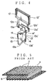
- That is, a circuit protection device provided with a PTC element against an overcurrent can interrupt the circuit by the increased resistance in the PTC element due to the heat generation in the PTC element by the current. Thence, a recovery of the protection circuit requires returning the PTC element to its usual temperature condition. To enhance heat radiation of a PTC element, Japanese Patent Laid-open No. 2-41161 has proposed a PTC element a having a conducting polymer element b with a corrugating portion c, as shown in FIG. 5.
- However, the conducting polymer element b with the corrugating portion c gives little effect in heat radiation without a surrounding air flow, resulted in requiring a considerably long recovery time in the PTC element.
- Moreover, Japanese Patent Application Laid-open No. 61-234502 discloses, as shown in FIG. 6, an application example of a PTC element d received in a protecting case e. However, the insufficient heat radiation from the covered space requires much recovery time for the PTC element d because of cooling only by itself, which is a drawback in the example.
- Generally, an electrical junction box has a capped cover to prevent falling-out of electrical parts. For example, Japanese Utility Model Application Laid-open No. 1-134350, as shown in FIG. 7, discloses an electrical junction box having a cover f, a projection g formed on the cover f abutting against the top of an electric fuse h to prevent falling-out of the fuse. However, the projection g gives no heat radiation effect. Thence, a PTC element accompanying heat generation and received in an electrical junction box requires much recovery time of the PTC element due to the insufficient heat radiation. Further, this causes a heat expansion and deformation in the cover of the junction box, which could bring about such a problem as a failure in a circuit therein.
- The US-A-4 499 517 discloses a motor protector particularly adapted for use with compressors, the motor protector comprising: a thermally and electrically conductive metallic housing generally in the configuration'of a parallelepiped having a bottom wall and four side walls extending therefore to form a switch chamber, a thermally and electrically conductive lid to close the chamber, electrically insulative gasket means disposed between the housing and the lid to electrically separate the housing from the lid and means to attach the lid to the housing, a thermally responsive switch means disposed in the chamber adapted to connect an disconnect the housing and the lid upon the occurrence of selected thermal conditions, a portion of the switch means mounted on the lid and another portion of the switch means mounted in the housing, and terminal means respectively attached to the housing and the lid.
- In view of the above-mentioned drawbacks, the present invention aims to improve the cover structure of the electrical junction boxes to enable a smooth heat radiation of the PTC element, which can reduce the recovery time of a protection circuit including the PTC element. The invention also provides a PTC element assembly with its mounting members for an electrical junction box to enable the easy mounting and dismounting, which giving a more efficient maintenance work of the assembly.
- For achieving the object, a PTC element and its mounting member assembly for an electrical junction box according to this invention includes:
- a plurality of supporting columns extending downwardly from a top wall of a cover attached to the electrical junction box body,
- a case surrounding the PTC element and having projecting bars extending in the direction parallel to said supporting columns, and
- a guiding groove formed in each of the supporting columns and receiving one of the projecting bars so as to hold the case.
-
- Preferably, the case surrounding the PTC element can be attached to a housing jointed to an opposing connector provided in the junction box body;
- the assembly further comprises a pair of connecting terminal strips each having a connecting piece at one end thereof and a male electrical contacting portion at the other end,
- the terminal strips being able to be inserted into the connector housing,
- the connecting pieces being connected to a pair of electric pole plates of the PTC element and received in the case,
- the electrical contacting portions being able to connect to relative terminal fittings in the opposing connector.
-
- Advantageously, the housing has a supporting base and a pair of terminal slots formed in the supporting base and inserting the connecting terminal strips, the housing supporting portion having an outer periphery formed with a projecting portion that engages with the case.
- Moreover, each of the connecting terminal strips has effectively a heat radiation face between the connecting piece and the electrical contacting portion, the connecting terminal strip further having a saw-tooth face at each side end thereof.
-
- FIG. 1 is an exploded perspective view of an embodiment of a PTC element and its mounting member assembly for an electrical junction box according to the invention;
- FIG. 2 is a top view showing major parts in a top wall of a cover shown in FIG. 1;
- FIG. 3 is a sectional view taken on X-X in FIG. 2;
- FIG. 4 is a perspective view showing connecting terminal strips in another embodiment of the invention;
- FIG. 5 is a perspective view showing a previously known structure including a conducting polymer element, which composes a PTC element;
- FIG. 6 is a sectional view showing another previously known PTC element having been enclosed in a case; and
- FIG. 7 is a sectional view showing a previously known structure of a cover for an electrical junction box.
-
- An embodiment of the invention will be discussed hereinafter.
- FIG. 1 shows an exploded perspective view of a PTC element and its mounting member assembly, which is an embodiment of the invention, for an electrical junction box.
- In FIG. 1, denoted 1 is an electrical junction box body; 2 is a cover attached to the
box body 1; and 3 is a protective case engaging with ahousing 4 and receiving a PTC element 6. The element 6 connects to connectingterminal strips 5, 5'. - The
junction box body 1 includes awiring board 7 mounted with anopposing connector 8 which electrically connects to theterminal strips 5, 5'in thehousing 4. - The
cover 2 shapes like a box molded of a synthetic resin having a comparatively better thermal conductivity, of which anopening periphery 2a is secured to an alignedopposing periphery 1a of thejunction box body 1 by lock fittings (not shown). On atop wall 2b of thecover 2, as shown in FIGS. 2 and 3, there are four supportingcolumns 9 extending in the attaching direction of thecover 2, each having a guidinggroove 9a. - The
case 3 cylindrically formed of a thin metal sheet receives the PTC element 6 therein for protection. Thecase 3 has an outerperipheral wall 3a with aprojecting bars 10 corresponding to the guidinggrooves 9a formed in the supportingcolumns 9 downwardly extending from thecover 2. - The
housing 4 composes a connector supporting the PTC element 6 and jointing to theopposing connector 8. Thehousing 4 molded of a synthetic resin includes a circular supportingportion 4a and afemale engagement surface 4b. - The supporting
portion 4a of thehousing 4 hasterminal insertion holes 11, 11' for inserting and securing the connectingterminal strips 5, 5'. The supportingportion 4a has a circular periphery formed with acircumferential projecting portion 4c to receive thecase 3. - The connecting
terminal strips 5, 5' each formed by bending and cutting an electrically conductive metal plate, which have a connectingpiece electrical contacting portion - The PTC element 6 includes a couple of
electric pole plates 12, 12' and an electrically conducting polymer composition sandwiched between the couple of the plates, which gives a PTC effect. Theelectric pole plate 12, 12' connects each to the connectingpiece terminal strips 5, 5' by way of alead piece connecting terminal strip 5, 5' engaged to the relative connector. - The connecting
terminal strips 5, 5' are secured to the supportingportion 4a by forcibly inserting theelectrical contacting portions terminal insertion holes 11, 11' to extend from the supportingportion 4a of thehousing 4 to a connectingportions 4b. After thehousing 4 has received the connectingterminal strips 5, 5', the projectingportion 4c engages with thecase 3 so that the PTC element 6 is enclosed by thecase 3. - The
housing 4 having secured the connectingterminal strips 5, 5' engages to theopposing connector 8. Thus, thehousing 4 couples to thewiring board 7 so that the electrical contactingportions terminal strips 5, 5' connect to female terminal fittings (not shown) in theopposing connector 8. - Further, the
projecting bars 10 of thecase 3 are inserted in the guidinggrooves 9a of the supportingcolumn 9 on thecover 2. Then, pushing thecover 2 toward thejunction box body 1 advances the projectingbars 10 in the guidinggroove 9a so that thecover 2 is attached on thejunction box body 1. - In use, the
case 3 has connected to thecover 2 with the projectingbars 10 engaged with the guidinggrooves 9a formed in the supportingcolumns 9. Thence, thecase 3 is stably retained without a structural chattering even by a relative motor vehicle vibration. Further, the heat generated by the PTC element 6 in thecase 3 transfer promptly to the projectingbar 10 of thecase 3 and the supportingcolumn 9 on thecover 2. This enhances radiation of the generated heat, resulted in reduction in recovery time of a protection circuit including the PTC element 6. - In addition, the better heat radiation eliminates an unusual temperature increase in the
junction box body 1. - FIG. 4 is a perspective view of connecting
terminal strips 13, 13' in another embodiment of the present invention, which have connected to the PTC element 6. - The connecting
terminal strips 13, 13' have respectively aheat radiation face piece portion tooth face 14 or 14' at each side end thereof. The connectingpieces portions pieces portions terminal strips 5, 5'. Hence, the heat radiation faces 13c, 13c' provided with the saw-tooth faces 14, 14' in the connectingterminal strips 13, 13', advantageously further enhances the heat radiation. - Next, operational effects of the invention will be discussed hereinafter.
- In the present invention, the case enclosing the PTC element is secured to the supporting columns downwardly extending from the cover. Thence, the heat generated by the PTC element conducts from the case to the supporting columns to effectively radiate from the top wall of the cover. This eliminates deformation of the case due to thermal expansion and reduces recovery time of a protection circuit including the PTC element. In addition, the heat radiation faces with the saw-tooth faces in the connecting terminal strips further enhances the heat radiation effect. Moreover, the supporting columns of the cover secures the case so that falling-out of the case, even when the junction box receives vibration from a vehicle equipped with the box is certainly prevented. Besides, in capping the cover on the junction box body, the guiding grooves of the supporting columns and the relative projecting bars of the case act as a positioning guide, which provides a better assembling process thereof. Thence, this invention improves the electrical junction box in its circuit performance and in assembling work thereof.
Claims (5)
- A PTC element and its mounting member assembly for an electrical junction box comprising:a plurality of supporting columns (9) extending downwardly from a top wall (2b) of a cover (2) attached to the electrical junction box body (1),a case (3) surrounding said PTC element (6) and having projecting bars (10) extending in the direction parallel to said supporting columns (9), anda guiding groove (9a) formed in each of said supporting columns (9) and receiving one of said projecting bars (10) so as to hold said case (3).
- A PTC element and its mounting member assembly as claimed in claim 1, wherein said case (3) surrounding said PTC element (6) can be attached to a housing (4) jointed to an opposing connector (8) provided in the junction box body (1);
said assembly further comprises a pair of connecting terminal strips (5, 5'; 13, 13') each having a connecting piece (5a, 5a'; 13a, 13a') at one end thereof and a male electrical contacting portion (5b, 5b'; 13b, 13b') at the other end,
said terminal strip (5, 5'; 13, 13') being able to be inserted into said connector housing (4),
said connecting pieces (5a, 5a'; 13, 13a') being connected to a pair of electric pole plates (12, 12') of said PTC element (6) and received in said case (3),
said electrical contacting portions (5b, 5b', 13b, 13b') being able to connect to relative terminal fittings in the opposing connector (8). - A PTC element and its mounting member assembly as claimed in claim 2, wherein said housing (4) has a supporting base (4a) and a pair of terminal slots (11, 11') formed in the supporting base (4a) and inserting said connecting terminal strips (5, 5', 13, 13'), the housing supporting portion (4a) having an outer periphery formed with a projecting portion (4c) that engages with the case (3).
- A PTC element and its mounting member assembly as claimed in claim 2, wherein each of said connecting terminal strips (13, 13') has a heat radiation face (13c, 13c') between said connecting piece (13a, 13a') and said electrical contacting portion (13b, 13b').
- A PTC element and its mounting member assembly as claimed in claim 4, wherein each of said connecting terminal strips (13, 13') further has a saw-tooth face (14, 14') at each side end thereof.
Applications Claiming Priority (3)
| Application Number | Priority Date | Filing Date | Title |
|---|---|---|---|
| JP64770/96 | 1996-03-21 | ||
| JP06477096A JP3194466B2 (en) | 1996-03-21 | 1996-03-21 | Mounting structure of PTC element to electrical junction box |
| JP6477096 | 1996-03-21 |
Publications (3)
| Publication Number | Publication Date |
|---|---|
| EP0797221A2 EP0797221A2 (en) | 1997-09-24 |
| EP0797221A3 EP0797221A3 (en) | 1998-10-21 |
| EP0797221B1 true EP0797221B1 (en) | 2002-09-18 |
Family
ID=13267776
Family Applications (1)
| Application Number | Title | Priority Date | Filing Date |
|---|---|---|---|
| EP97104804A Expired - Lifetime EP0797221B1 (en) | 1996-03-21 | 1997-03-20 | PTC element and its mounting member assembly for electrical junction box |
Country Status (4)
| Country | Link |
|---|---|
| US (1) | US5793277A (en) |
| EP (1) | EP0797221B1 (en) |
| JP (1) | JP3194466B2 (en) |
| DE (1) | DE69715493T2 (en) |
Families Citing this family (6)
| Publication number | Priority date | Publication date | Assignee | Title |
|---|---|---|---|---|
| JP3052843B2 (en) * | 1996-07-03 | 2000-06-19 | 住友電装株式会社 | Electrical junction box |
| JP3494360B2 (en) * | 1999-06-15 | 2004-02-09 | 矢崎総業株式会社 | Electrical equipment |
| JP2005130633A (en) | 2003-10-24 | 2005-05-19 | Yazaki Corp | Electrical junction box |
| JP4161877B2 (en) * | 2003-11-05 | 2008-10-08 | 住友電装株式会社 | Circuit structure, manufacturing method thereof and power distribution unit |
| JP2006074872A (en) * | 2004-08-31 | 2006-03-16 | Sumitomo Wiring Syst Ltd | Electric connection box for automobile |
| CN206059059U (en) * | 2016-09-07 | 2017-03-29 | 南京南瑞继保电气有限公司 | A kind of shell mechanism of Planar capacitor |
Family Cites Families (16)
| Publication number | Priority date | Publication date | Assignee | Title |
|---|---|---|---|---|
| US2815423A (en) * | 1950-01-28 | 1957-12-03 | Bendix Aviat Corp | Electric control device |
| US2754472A (en) * | 1950-03-10 | 1956-07-10 | Bendix Aviat Corp | Thermal control device |
| US4355458A (en) * | 1978-09-08 | 1982-10-26 | General Electric Company | Method of making an electrical control |
| US4327351A (en) * | 1979-05-21 | 1982-04-27 | Raychem Corporation | Laminates comprising an electrode and a conductive polymer layer |
| US4445026A (en) * | 1979-05-21 | 1984-04-24 | Raychem Corporation | Electrical devices comprising PTC conductive polymer elements |
| US4272471A (en) * | 1979-05-21 | 1981-06-09 | Raychem Corporation | Method for forming laminates comprising an electrode and a conductive polymer layer |
| US4499517A (en) * | 1983-11-14 | 1985-02-12 | Texas Instruments Incorporated | Motor protector particularly suited for use with compressor motors |
| US4685025A (en) * | 1985-03-14 | 1987-08-04 | Raychem Corporation | Conductive polymer circuit protection devices having improved electrodes |
| US4780698A (en) * | 1987-04-30 | 1988-10-25 | Texas Instruments Incorporated | Circuit interrupter device and method for making |
| JPH01134350A (en) * | 1987-11-20 | 1989-05-26 | Nec Corp | Camera |
| JPH0241161A (en) * | 1988-07-28 | 1990-02-09 | Atsuo Taniguchi | Method and apparatus for purifying instrument |
| FR2660483B1 (en) * | 1990-03-28 | 1994-09-09 | Jaeger | FLAT POWER RESISTANCE. |
| DE4292013T1 (en) * | 1991-06-26 | 1994-06-09 | Tdk Corp | Device for a thermistor with a positive characteristic |
| CN1040713C (en) * | 1993-08-23 | 1998-11-11 | 雷伊化学公司 | Use of PCT Device in wiring harnesses |
| WO1995013621A1 (en) * | 1993-11-12 | 1995-05-18 | Alcoa Fujikura Ltd. | Short circuit protected splice connector |
| US5668521A (en) * | 1995-03-22 | 1997-09-16 | Littelfuse, Inc. | Three piece female blade fuse assembly having fuse link terminal with a clip receiving portion |
-
1996
- 1996-03-21 JP JP06477096A patent/JP3194466B2/en not_active Expired - Fee Related
-
1997
- 1997-03-19 US US08/821,573 patent/US5793277A/en not_active Expired - Fee Related
- 1997-03-20 EP EP97104804A patent/EP0797221B1/en not_active Expired - Lifetime
- 1997-03-20 DE DE69715493T patent/DE69715493T2/en not_active Expired - Fee Related
Also Published As
| Publication number | Publication date |
|---|---|
| DE69715493T2 (en) | 2003-05-22 |
| JP3194466B2 (en) | 2001-07-30 |
| EP0797221A3 (en) | 1998-10-21 |
| EP0797221A2 (en) | 1997-09-24 |
| US5793277A (en) | 1998-08-11 |
| DE69715493D1 (en) | 2002-10-24 |
| JPH09260103A (en) | 1997-10-03 |
Similar Documents
| Publication | Publication Date | Title |
|---|---|---|
| US4837546A (en) | Fuse block | |
| US20080061920A1 (en) | Fuse cavity structure and electric connection box | |
| JP2587911Y2 (en) | Fixing structure of electric connection box and busbar for mini fuse | |
| MXPA96006393A (en) | Electric connection pin | |
| JP2003037920A (en) | Electrical connection box | |
| EP4125156B1 (en) | Connector | |
| JP3248480B2 (en) | Distribution box | |
| EP4108513A1 (en) | Connector | |
| GB2197759A (en) | Electric fuse | |
| US5793277A (en) | PTC element and its mounting member assembly for electrical junction box | |
| JP3112390B2 (en) | Connection structure of screw-type connector | |
| US6099352A (en) | Shielded connector | |
| JP7264655B2 (en) | electric junction box | |
| JP5441260B2 (en) | Fusible link unit | |
| US5014035A (en) | Bimetallic circuit breaker with insulated terminal assembly | |
| CA2184569C (en) | Electrical receptacle assembly with enhanced heat dissipation arrangement | |
| US20120108084A1 (en) | Electrical Connection Bar and Adapted Connection Device | |
| US5880666A (en) | Fuse with press-connecting terminals and wire cutter | |
| JPH07111888B2 (en) | Power clip | |
| US4567390A (en) | Internal line break assembly | |
| JP2947079B2 (en) | Connection structure of electrical junction box | |
| JPH0988824A (en) | Cover structure for exposed electric component of compressor | |
| CN1068969C (en) | Heat overload protector | |
| JPH0917495A (en) | Plug socket device | |
| EP1310972B1 (en) | Fuse box for vehicles |
Legal Events
| Date | Code | Title | Description |
|---|---|---|---|
| PUAI | Public reference made under article 153(3) epc to a published international application that has entered the european phase |
Free format text: ORIGINAL CODE: 0009012 |
|
| AK | Designated contracting states |
Kind code of ref document: A2 Designated state(s): DE FR GB |
|
| PUAL | Search report despatched |
Free format text: ORIGINAL CODE: 0009013 |
|
| AK | Designated contracting states |
Kind code of ref document: A3 Designated state(s): DE FR GB |
|
| 17P | Request for examination filed |
Effective date: 19990420 |
|
| 17Q | First examination report despatched |
Effective date: 20010607 |
|
| GRAG | Despatch of communication of intention to grant |
Free format text: ORIGINAL CODE: EPIDOS AGRA |
|
| GRAG | Despatch of communication of intention to grant |
Free format text: ORIGINAL CODE: EPIDOS AGRA |
|
| GRAH | Despatch of communication of intention to grant a patent |
Free format text: ORIGINAL CODE: EPIDOS IGRA |
|
| GRAH | Despatch of communication of intention to grant a patent |
Free format text: ORIGINAL CODE: EPIDOS IGRA |
|
| GRAA | (expected) grant |
Free format text: ORIGINAL CODE: 0009210 |
|
| AK | Designated contracting states |
Kind code of ref document: B1 Designated state(s): DE FR GB |
|
| REG | Reference to a national code |
Ref country code: GB Ref legal event code: FG4D |
|
| REF | Corresponds to: |
Ref document number: 69715493 Country of ref document: DE Date of ref document: 20021024 |
|
| ET | Fr: translation filed | ||
| PLBE | No opposition filed within time limit |
Free format text: ORIGINAL CODE: 0009261 |
|
| STAA | Information on the status of an ep patent application or granted ep patent |
Free format text: STATUS: NO OPPOSITION FILED WITHIN TIME LIMIT |
|
| 26N | No opposition filed |
Effective date: 20030619 |
|
| PGFP | Annual fee paid to national office [announced via postgrant information from national office to epo] |
Ref country code: FR Payment date: 20060308 Year of fee payment: 10 |
|
| PGFP | Annual fee paid to national office [announced via postgrant information from national office to epo] |
Ref country code: DE Payment date: 20060316 Year of fee payment: 10 |
|
| GBPC | Gb: european patent ceased through non-payment of renewal fee |
Effective date: 20070320 |
|
| REG | Reference to a national code |
Ref country code: FR Ref legal event code: ST Effective date: 20071130 |
|
| PG25 | Lapsed in a contracting state [announced via postgrant information from national office to epo] |
Ref country code: DE Free format text: LAPSE BECAUSE OF NON-PAYMENT OF DUE FEES Effective date: 20071002 |
|
| PG25 | Lapsed in a contracting state [announced via postgrant information from national office to epo] |
Ref country code: GB Free format text: LAPSE BECAUSE OF NON-PAYMENT OF DUE FEES Effective date: 20070320 |
|
| PG25 | Lapsed in a contracting state [announced via postgrant information from national office to epo] |
Ref country code: FR Free format text: LAPSE BECAUSE OF NON-PAYMENT OF DUE FEES Effective date: 20070402 |
|
| PGFP | Annual fee paid to national office [announced via postgrant information from national office to epo] |
Ref country code: GB Payment date: 20060315 Year of fee payment: 10 |