EP0797019B1 - End bearing for a one-way clutch - Google Patents
End bearing for a one-way clutch Download PDFInfo
- Publication number
- EP0797019B1 EP0797019B1 EP95933630A EP95933630A EP0797019B1 EP 0797019 B1 EP0797019 B1 EP 0797019B1 EP 95933630 A EP95933630 A EP 95933630A EP 95933630 A EP95933630 A EP 95933630A EP 0797019 B1 EP0797019 B1 EP 0797019B1
- Authority
- EP
- European Patent Office
- Prior art keywords
- end bearing
- bearing according
- coating
- alloy
- hard coating
- Prior art date
- Legal status (The legal status is an assumption and is not a legal conclusion. Google has not performed a legal analysis and makes no representation as to the accuracy of the status listed.)
- Expired - Lifetime
Links
Images


Classifications
-
- F—MECHANICAL ENGINEERING; LIGHTING; HEATING; WEAPONS; BLASTING
- F16—ENGINEERING ELEMENTS AND UNITS; GENERAL MEASURES FOR PRODUCING AND MAINTAINING EFFECTIVE FUNCTIONING OF MACHINES OR INSTALLATIONS; THERMAL INSULATION IN GENERAL
- F16C—SHAFTS; FLEXIBLE SHAFTS; ELEMENTS OR CRANKSHAFT MECHANISMS; ROTARY BODIES OTHER THAN GEARING ELEMENTS; BEARINGS
- F16C33/00—Parts of bearings; Special methods for making bearings or parts thereof
- F16C33/02—Parts of sliding-contact bearings
- F16C33/04—Brasses; Bushes; Linings
- F16C33/06—Sliding surface mainly made of metal
- F16C33/12—Structural composition; Use of special materials or surface treatments, e.g. for rust-proofing
-
- F—MECHANICAL ENGINEERING; LIGHTING; HEATING; WEAPONS; BLASTING
- F16—ENGINEERING ELEMENTS AND UNITS; GENERAL MEASURES FOR PRODUCING AND MAINTAINING EFFECTIVE FUNCTIONING OF MACHINES OR INSTALLATIONS; THERMAL INSULATION IN GENERAL
- F16C—SHAFTS; FLEXIBLE SHAFTS; ELEMENTS OR CRANKSHAFT MECHANISMS; ROTARY BODIES OTHER THAN GEARING ELEMENTS; BEARINGS
- F16C33/00—Parts of bearings; Special methods for making bearings or parts thereof
- F16C33/02—Parts of sliding-contact bearings
- F16C33/04—Brasses; Bushes; Linings
- F16C33/06—Sliding surface mainly made of metal
- F16C33/12—Structural composition; Use of special materials or surface treatments, e.g. for rust-proofing
- F16C33/122—Multilayer structures of sleeves, washers or liners
-
- F—MECHANICAL ENGINEERING; LIGHTING; HEATING; WEAPONS; BLASTING
- F16—ENGINEERING ELEMENTS AND UNITS; GENERAL MEASURES FOR PRODUCING AND MAINTAINING EFFECTIVE FUNCTIONING OF MACHINES OR INSTALLATIONS; THERMAL INSULATION IN GENERAL
- F16D—COUPLINGS FOR TRANSMITTING ROTATION; CLUTCHES; BRAKES
- F16D41/00—Freewheels or freewheel clutches
- F16D41/06—Freewheels or freewheel clutches with intermediate wedging coupling members between an inner and an outer surface
- F16D41/069—Freewheels or freewheel clutches with intermediate wedging coupling members between an inner and an outer surface the intermediate members wedging by pivoting or rocking, e.g. sprags
- F16D41/07—Freewheels or freewheel clutches with intermediate wedging coupling members between an inner and an outer surface the intermediate members wedging by pivoting or rocking, e.g. sprags between two cylindrical surfaces
-
- F—MECHANICAL ENGINEERING; LIGHTING; HEATING; WEAPONS; BLASTING
- F16—ENGINEERING ELEMENTS AND UNITS; GENERAL MEASURES FOR PRODUCING AND MAINTAINING EFFECTIVE FUNCTIONING OF MACHINES OR INSTALLATIONS; THERMAL INSULATION IN GENERAL
- F16H—GEARING
- F16H57/00—General details of gearing
- F16H57/08—General details of gearing of gearings with members having orbital motion
-
- F—MECHANICAL ENGINEERING; LIGHTING; HEATING; WEAPONS; BLASTING
- F16—ENGINEERING ELEMENTS AND UNITS; GENERAL MEASURES FOR PRODUCING AND MAINTAINING EFFECTIVE FUNCTIONING OF MACHINES OR INSTALLATIONS; THERMAL INSULATION IN GENERAL
- F16C—SHAFTS; FLEXIBLE SHAFTS; ELEMENTS OR CRANKSHAFT MECHANISMS; ROTARY BODIES OTHER THAN GEARING ELEMENTS; BEARINGS
- F16C2204/00—Metallic materials; Alloys
- F16C2204/60—Ferrous alloys, e.g. steel alloys
-
- F—MECHANICAL ENGINEERING; LIGHTING; HEATING; WEAPONS; BLASTING
- F16—ENGINEERING ELEMENTS AND UNITS; GENERAL MEASURES FOR PRODUCING AND MAINTAINING EFFECTIVE FUNCTIONING OF MACHINES OR INSTALLATIONS; THERMAL INSULATION IN GENERAL
- F16D—COUPLINGS FOR TRANSMITTING ROTATION; CLUTCHES; BRAKES
- F16D41/00—Freewheels or freewheel clutches
- F16D41/06—Freewheels or freewheel clutches with intermediate wedging coupling members between an inner and an outer surface
- F16D2041/0601—Freewheels or freewheel clutches with intermediate wedging coupling members between an inner and an outer surface with a sliding bearing or spacer
Definitions
- the invention relates to an end bearing for one-way clutch, and more particularly, to an end bearing for one-way clutch which is preferred for use in an automatic transmission, for example.
- a one-way clutch comprising an annular inner race which is disposed radially inward, an annular outer race disposed in surrounding relationship with the inner race, a plurality of sprags slidably interposed between the inner and the outer race, a retainer for retaining the sprags, ribbon springs for urging the sprags against the track surface of the both races, and an annular end bearing slidably interposed between the peripheral surfaces of the both races at locations axially outside the retainer for supporting a radial load acting upon the both races.
- An end bearing for one-way clutch of the prior art can be categorized into 4 types.
- the end bearing is shaped from phosphor bronze sheet by a press operation.
- the end bearing is shaped by a press operation of an integral sheet-like material which results from sintering an iron sheet and powder of phosphor bronze.
- the end bearing is formed by cutting a high-tensile brass to shape.
- a steel block is machined by a cutting operation, followed by a quenching, a tempering and a grinding operation, and finally a manganate phosphate film is applied to the surface thereof.
- an end bearing according to the first implementation exhibits a reduced rigidity, which causes an increased degree of elastic deformation when the magnitude of the radial load increases, which in turn results in a degraded functioning or sometimes a failure of the entire one-way clutch.
- An end bearing according to the second implementation undergoes a reduced amount of elastic deformation as compared with the first implementation, but because the iron sheet is tempered during the sintering step, there may be caused a reduction in the strength of the end bearing, which may be subject to a plastic deformation.
- An end bearing according to the third implementation requires an increased cost because of a high material cost.
- a required rigidity can be secured, but the manganate phosphate film which is formed on the surface thereof presents a poor affinity and self-lubrication capability. Accordingly, in order to secure a satisfactory anti-seizure resistance, a high dimensional accuracy is required during the manufacture, resulting in an increased cost of the entire one-way clutch.
- GB-A-2 285 290 on which the preamble of claim 1 is based, describes an end bearing for a one-way clutch.
- a steel body of the bearing is coated with a copper alloy layer which in turn is coated with a tin layer.
- JP 62 - 110021 discloses a bearing surface having two soft coating layers, the innermost one of which is an Sn alloy.
- the present invention provides an end bearing for a one-way clutch, as set forth in claim 1.
- the use of the iron material for the body allows a sufficient rigidity to withstand the radial load acting on the end bearing to be secured. Since the surface of the end bearing which is disposed for sliding contact comprises the soft coating, the affinity of the end bearing with the inner and the outer race as it is disposed for sliding contact therewith is improved, thus providing an end bearing having an improved anti-seizure resistance and durability.
- the interposition of the hard coating between the body and the soft coating is effective to prevent a sliding contact with the steel sheet which exhibits a poor sliding response in the event the soft coating, which provides the sliding surface, becomes abraded, but the hard coating prevents an abrasion of the body from occurring, thus improving the anti-seizure resistance.
- the hard coating prevents an abrasion of the body from occurring, thus improving the anti-seizure resistance.
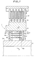
- Fig.1 shows an essential part of an automatic transmission for automobile in cross section.
- the one-way clutch 1 comprises an inner race 2 having an annular track surface 2a, an outer race 3 having an annular track surface 3a, a plurality of sprags 4 disposed between the both races 2,3 for engagement with the both track surfaces 2a, 3a to transmit a torque, a retainer 7 including a pair of inner and outer annular members 5,6 which maintain the sprags 4 at an equal circumferential spacing therebetween, ribbon springs 8 disposed between the both annular members 5,6 to apply a moment to the sprags 4 in a direction to engage or mesh with the both track surfaces 2a, 3a, and an end bearing 11 including a pair of annular members 9, 10 according to the invention which are disposed at locations adjacent to the axial ends of the retainer 7.
- the inner race 2 rotates together with a rotary shaft, not shown, while the outer race 3 engages with a friction plate assembly 12, known in the art, through a plurality of axial grooves 3b.
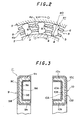
- Each sprag 4 has a dimension R1 which is chosen to be greater than a dimension RO as shown in Fig.2, and is formed with recesses 4a on the both sides.
- the ribbon spring 8 is disposed across opposing recesses 4a of adjacent sprags 4 to apply a counter-clockwise acting moment to the sprags 4, as viewed in Fig.2. In this manner, each sprag 4 cannot rotate in the counter-clockwise direction, as viewed in Fig.2, but is slightly rotatable in the clockwise direction.
- the inner race 2 when the inner race 2 tends to rotate counter-clockwise relative to the outer race 3, the inner race 2 slides with respect to the individual sprags 4, and can thus freely rotatable in the counter-clockwise direction, whereby a torque cannot be transmitted from the inner race 2 to the outer race 3.
- the inner race 2 when the inner race 2 tends to rotate clockwise relative to the outer race 3, the inner race 2 engages or meshes with the individual sprags 4, which simultaneously engage or mesh with the outer race 3, thus transmitting a torque from the inner race 2 to the outer race 3 and allowing the one-way clutch 1 to rotate integrally in the clockwise direction.
- the annular members 9, 10 which constitute the end bearing 11 comprise radially extending annular portion 9a, 10a, as well as tubular portions 9b, 10b extending axially from the inner periphery of the annular portions around the inner periphery and tubular portions 9c, 10c axially extending from the outer periphery of the annular portions around the outer periphery.
- the annular members 9, 10 are channel-shaped in section.
- the axially left end of the retainer 7 is positioned between the tubular portion 9b extending around the inner periphery and the tubular portion 9c extending around the outer periphery of the left-hand annular member 9 while the axially right end of the retainer 7 is positioned between the tubular portion 10b extending around the inner periphery and the tubular portion 10c extending around the outer periphery of the right-hand annular member 10.
- the inner peripheral surfaces (or sliding surfaces) of the both tubular portions 9b, 10b extending around the inner periphery of the both annular members 9, 10 are disposed for sliding contact with the outer peripheral surface of the inner race 2 while simultaneously the outer peripheral surfaces (or sliding surfaces) of the tubular portions 9c, 10c extending around the outer periphery of the both annular members 9, 10 are disposed for sliding contact with the inner peripheral surface of the outer race 3.
- an alignment between the axes of the both races 4, 5 can be achieved, thus supporting the both races 4, 5 in the radial direction.
- the end bearing of the invention is constructed in a manner discussed below, with reference to Figures 8 to 11, to improve the bearing performance.
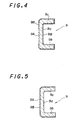
- the respective annular members 9, 10 which constitute together the end bearing 11 comprise annular bodies 9A, 10A which are channel-shaped in section, hard coatings 9B, 10B defined by a hard plating formed over the entire surface of the tubular portions 9b, 10b extending around the inner periphery and the tubular portions 9c, 10c extending around the outer periphery of the bodies 9A, 10A except for the end faces thereof, and soft coatings 9C, 10C defined by a soft plating applied to the entire surface of the hard coatings 9B, 10B inclusive of the end faces.
- the soft coating comprises a Pb alloy.
- a process of manufacturing the end bearing 11 will be described. Initially a steel sheet having a thickness of 1 mm and hardness of Hv100 to 180 and having a Cu ( copper) plating applied to a thickness of 8 ⁇ m on the front surface and to a thickness of 1 ⁇ m on the rear surface is provided. The steel sheet is stamped by a press operation into a channel-shaped cross section so that the Cu plating applied to the thickness of 8 ⁇ m represents the outer surface. In this manner, the bodies 9A, 10A which comprise a steel sheet, and the hard coatings 9B, 10B which comprise Cu plating are simultaneously formed.
- outer surface of the end bearing 11 is intended to refer generically the sliding surfaces (or inner peripheral surfaces) of the tubular portions 9b, 10b extending around the inner periphery, the sliding surfaces (outer peripheral surfaces) of the tubular portions 9c, 9d extending around the outer periphery and one of the surfaces of the annular portions 9a, 10a which join these tubular portions.
- the term “inner surface” of the end bearing 11 is intended to refer generically the outer peripheral surfaces of the tubular portions 9b, 10b extending around the inner periphery, the inner peripheral surfaces of the tubular portions 9c, 10c extending around the outer periphery and the other surface of the annular portions of the annular portions 9a, 10a which join between these tubular portions.
- the entire exposed surface is applied with the Pb alloy to a thickness of 2 ⁇ m, which provides the soft coatings 9C, 10C. This completes the end bearing 11.
- a heat treatment at a temperature from 160 to 250°C for a time interval on the order of one hour may be applied to the end bearing 11 on which the soft coatings 9C, 10C are formed.
- Such a heat treatment enables a diffusion of plating metals, which form the hard coatings 9B, 10B and the soft coatings 9C, 10C, into each other to be promoted. Since the temperature of the end bearing 11 rises to the order of the 120°C during the operation, such diffusion proceeds during the operation without applying a separate heat treatment during the manufacture.
- a steel sheet which is previously formed with Cu plating on the front and the rear surface is provided, and is then stamped by a press operation to form the bodies 9A, 10A and the hard coatings 9B, 10B simultaneously.
- the application of the plating to the steel sheet improves the dimensional accuracy.
- a steel sheet having no Cu plating applied to its front and rear surfaces may be provided, and is stamped by a press operation into channel-shaped cross section to form the bodies 9A, 10A.
- a Cu plating may be applied to only the outer surface of the bodies 9A, 10A to form the hard coatings 9B, 10B. It should be understood that Cu plating may be applied to the entire exposed surface of the bodies 9A, 10A.
- a cutting operation may be used to machine the steel block to form the bodies 9A, 10A into the configuration mentioned above.
- the material for the hard coatings 9B, 10B may comprise Ni (nickel), Ni-P (nickel-phosphorus), Ni-B (nickel-boron), Al (aluminum) or Zn (zinc).
- the thickness of the hard coatings 9B, 10B is preferably in a range from 0.5 ⁇ m to 50 ⁇ m, and more preferably, in a range from 1 ⁇ m to 30 ⁇ m.
- the material for the soft coatings 9C, 10C may comprise Pb-Sn (lead-tin), Pb-Sn-Cu (lead-tin-copper), or Pb-Sn-In (lead-tin-indium).
- the thickness of the soft coatings 9C, 10C is preferably in a range from 0.2 ⁇ m to 50 ⁇ m, and more preferably in a range from 0.5 ⁇ m to 30 ⁇ m.
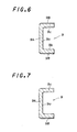
- Figs.4 to 7 illustrate different constructions of the hard coating 9B (10B).
- a hard coating 9B is formed on such end faces in an embodiment shown in Fig.4.
- the hard coating 9B is applied over the entire exposed surface of the body 9A.
- a hard coating 9B is applied to only the outer surface of the body 9A.
- a hard coating 9B is formed on only the sliding surface of the tubular portion 9c extending around the outer periphery and the sliding surface of the tubular portion 9b extending around the inner periphery of the body 9A.
- a hard coating 9B is formed on only the sliding surface of the tubular portion 9b extending around the inner periphery of the body 9A.
- Figs.8 to 10 show embodiments illustrating different constructions of the soft coating 9C (10C). While the soft coating 9C (10C) shown in Fig.3 comprises a single plated layer, Figs.8 to 10 illustrate a soft coating 9C which comprises a plurality of plated layers, in accordance with the present invention, the innermost soft layer being Pb alloy.
- a soft coating 9C comprises two plated layers which are sequentially plated over the entire surface. More specifically, the soft coating 9C comprises an inner or first plated layer 9C-1 of Pb alloy, and an outer or second plated layer 9C-2 of either Sn or Sn alloy.
- Pb alloy generically includes Pb-Sn, Pb-Sn-Cu, Pb-Sn-In or any other Pb alloy, for example.
- a soft coating 9C comprises three plated layers which are sequentially plated over the entire surface. More specifically, the soft coating 9C comprises an innermost or first plated layer 9C-1 and an intermediate or second plated layer 9C-2, both of Pb alloy, and an outermost or third plated layer 9C-3 of Sn or Sn alloy.
- the first plated layer 9C-1 comprises Pb-Sn-Cu
- the intermediate or second plated layer 9C-2 comprises Pb-Sn-In.
- Pb-Sn-Cu is used in the first layer for the reason that it is harder than Pb-Sn-In used in the second layer.
- the first and the second layer may be interchanged without presenting any problem.
- a soft coating 9C comprises two plated layers only in a region which corresponds to sliding surfaces on the inside and the outside.
- a Pb alloy plating or specifically, a plating of Pb-Sn or Pb-Sn-Cu or Pb-Sn-In is applied to regions which correspond to the inner and the outer sliding surfaces after a hard coating 9B is formed on a body 9A, thus forming an inner or first plated layer 9C-1.
- an Sn or Sn alloy plating is applied to the entire exposed surface to form an outer or second plated layer 9C-2.
- Fig. 11 illustrates another embodiment of the invention.
- the soft coating 9C includes a first plated layer 9C-1 for the inner sliding surface. Subsequently, a second plated layer 9C-2 similar to that shown in Fig.10 is formed over the entire exposed surface. Accordingly, in the embodiment of Fig. 11, only the soft coating 9C which provides the inner sliding surface comprises two plated layers.
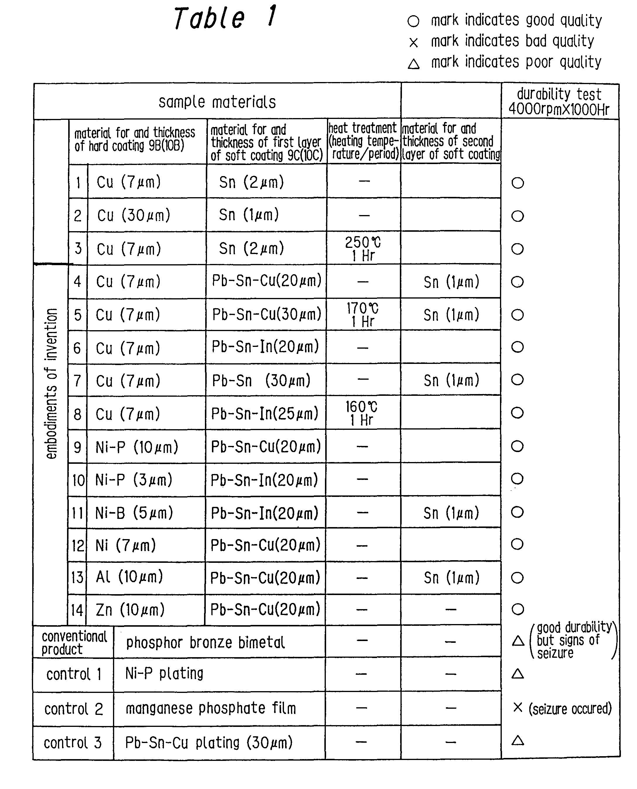
- Table 1 given below indicates results of a durability test which is conducted on end bearings 11 according to individual embodiments of the invention, a conventional end bearing and other controls.
- Examples 1-3, 6, 8-10, 12 and 14 are not embodiments of the invention.
- a lubricating oil having an oil temperature of 100°C is supplied to areas 20a, 20b, 20c, and 20d of sliding contact between the end bearings 11, 11' and the rotary shaft 20 at a rate of two liters per minute.
- the rotary shaft 20 is rotated at 4000 rpm, and during the rotation, a rotary load of about 3 kgf is applied to the respective end bearings 11, 11'.
- the conventional product indicated in table 1 is an end bearing which is shaped by a press operation from an iron sheet on which powder of phosphor bronze is uniformly dispersed and then sintered at about 860 °C .
- the conventional product exhibited a good durability, but showed a sign of seizure.
- the control 1 comprises a body similar to one used in the present embodiment and to which an Ni-P plating is applied as a hard surface treatment.
- the control 1 exhibited a poor durability.
- the control 2 comprises a body formed in the same manner as in the embodiment and having a surface which is coated by a manganate phosphate film. A seizure occurred with the control 2.
- the control 3 comprises a body formed in the similar manner as in the present embodiments and having a surface to which a Pb-Sn-Cu plating is applied to a thickness of 30 ⁇ m.
- the control 3 exhibited a poor durability.
- the end bearing 11 of the invention employs a steel sheet to construct the bodies 9A, 10A, which allows sufficient rigidity to be secured which is capable of withstanding a radial load.
- the interposition of the hard coatings 9B, 10B between the bodies 9A, 10A and the soft coatings 9C, 10C is effective to prevent an abrasion of the bodies 9A, 10A by the presence of the hard coatings 9B, 10B in the event the soft coatings 9C, 10C, which provide the sliding surfaces, become abraded. In this manner, the anti-seizure resistance can be improved.
Landscapes
- Engineering & Computer Science (AREA)
- General Engineering & Computer Science (AREA)
- Mechanical Engineering (AREA)
- Rolling Contact Bearings (AREA)
- Sliding-Contact Bearings (AREA)
Description
Claims (16)
- An end bearing (11) for a one-way clutch including an annular inner race (2), an annular outer race (3) surrounding the inner race (2), a plurality of sprags (4) slidably interposed between the inner and the outer race (2,3), a retainer (7) for retaining the sprags (4), and ribbon springs (8) for urging the sprags (4) against track surfaces (2a,3a) of the both races (2,3), in which the end bearing (11) is slidably interposed between the peripheral surfaces of the races (2,3) at a location axially outside the retainer (7) for supporting a radial load acting on the races (2,3);
the end bearing (11) comprising a body (9) formed of an iron material and including a tubular portion (9b) extending around the inner periphery, a tubular portion (9c) extending around the outer periphery of the end bearing (11), and an annular portion (9a) which joins the both tubular portions (9b,9c), a hard coating (9B) defined by a hard plating formed on the surface of the body, and a soft coating (9C) defined by a soft plating formed on the surface of the hard coating,
characterised in that the soft coating (9C) comprises double or triple plated layers and in that the innermost one of these layers comprises a Pb alloy. - An end bearing according to claim 1 in which the soft coating (9C) comprises one of Pb-Sn, Pb-Sn-Cu or Pb-Sn-In.
- An end bearing according to claim 1 or 2 in which the soft coating (9C) comprises double plated layers which are sequentially plated over the entire surface of the body, the first plated layer (9C-1) being of Pb alloy and second plated layer (9C-2) being of Sn or Sn alloy.
- An end bearing according to claim 1 or 2 in which the soft coating (9C) comprises triple plated layers which are sequentially plated over the entire surface of the body, the first and the second plated layers (9C-1, (9C-2) being of Pb alloy and the third plated layer (9C-3) being of Sn or Sn alloy.
- An end bearing according to claim 1 or 2 in which the soft coating (9C) comprises double plated layers, the first plated layer (9C-1) being of Pb alloy and applied only to inner and outer sliding surfaces of the bearing, the second plated layer (9C-2) being of Sn or Sn alloy and applied to the entire surface of the bearing inclusive of the first plated layer (9C-1).
- An end bearing according to claim 1 or 2 in which the soft coating comprises double plated layers, the first plated layer (9C-1) being of Pb alloy and applied only to an inner sliding surface of the bearing, the second plated layer (9C-2) being of Sn or Sn alloy and applied to the entire surface inclusive of the first plated layer.
- An end bearing according to any one of the preceding claims in which the hard coating (9B) comprises one of Cu, Ni, Ni-P, Ni-B, Al or Zn.
- An end bearing according to any one of the preceding claims in which the hard coating (9B) is formed on the surface of the body (9) except for the end faces of the tubular portions (9b,9c) which extend around the inner and the outer periphery of the end bearing (11).
- An end bearing according to any one of claims 1 to 7 in which the hard coating (9B) is formed over the entire surface of the body (9).
- An end bearing according to any one of claims 1 to 7 in which the hard coating (9B) is formed only on the outer surface of the body (9).
- An end bearing according to any one of claims 1 to 7 in which the hard coating (9B) is formed on only the sliding surfaces of both tubular portions (9b,9c) of the body (9).
- An end bearing according to any one of claims 1 to 7 in which the hard coating (9B) is formed only on the sliding surface of the tubular portion (9b) extending around the inner periphery of the body (9).
- An end bearing according to any one of the preceding claims in which the hard coating (9B) has a thickness in a range from 0.5µm to 50µm.
- An end bearing according to any one of the preceding claims in which the hard coating (9B) comprises one of Cu, Ni and Zn, a thermal diffusion of a component of the soft coating (9C) into the hard coating (9B) occurring upon being heated.
- An end bearing according to claim 15 in which the hard coating (9B) is subject to a heat treatment at a temperature from 160 to 250° for a time interval on the order of one hour.
- An end bearing according to any one of the preceding claims in which the soft coating has a thickness in a range from 0.2µm to 50µm.
Priority Applications (1)
| Application Number | Priority Date | Filing Date | Title |
|---|---|---|---|
| EP00116732A EP1054178B1 (en) | 1995-10-06 | 1995-10-06 | End bearing for one-way clutch |
Applications Claiming Priority (2)
| Application Number | Priority Date | Filing Date | Title |
|---|---|---|---|
| JP7395894A JP3599063B2 (en) | 1994-03-18 | 1994-03-18 | One-way clutch end bearing |
| PCT/JP1995/002050 WO1997013077A1 (en) | 1994-03-18 | 1995-10-06 | End bearing for a one-way clutch |
Related Child Applications (1)
| Application Number | Title | Priority Date | Filing Date |
|---|---|---|---|
| EP00116732A Division EP1054178B1 (en) | 1995-10-06 | 1995-10-06 | End bearing for one-way clutch |
Publications (3)
| Publication Number | Publication Date |
|---|---|
| EP0797019A1 EP0797019A1 (en) | 1997-09-24 |
| EP0797019A4 EP0797019A4 (en) | 1998-11-25 |
| EP0797019B1 true EP0797019B1 (en) | 2001-04-11 |
Family
ID=26415101
Family Applications (1)
| Application Number | Title | Priority Date | Filing Date |
|---|---|---|---|
| EP95933630A Expired - Lifetime EP0797019B1 (en) | 1994-03-18 | 1995-10-06 | End bearing for a one-way clutch |
Country Status (3)
| Country | Link |
|---|---|
| US (1) | US5570766A (en) |
| EP (1) | EP0797019B1 (en) |
| WO (1) | WO1997013077A1 (en) |
Families Citing this family (6)
| Publication number | Priority date | Publication date | Assignee | Title |
|---|---|---|---|---|
| FR2760057B1 (en) * | 1997-02-25 | 1999-04-02 | Skf France | FREE WHEEL DEVICE WITH RETAINING FLANGE AND METHOD FOR PLACING THE FLANGE |
| US6267508B1 (en) * | 1999-11-04 | 2001-07-31 | Federal-Mogul World Wide, Inc. | Sliding bearing having multilayer lead-free overplate and method of manufacture |
| US6705445B2 (en) | 2000-09-11 | 2004-03-16 | Koyo Seiko, Co., Ltd. | One-way clutch |
| JP2004011838A (en) * | 2002-06-10 | 2004-01-15 | Nsk Warner Kk | Stator equipped with one-way clutch |
| FR2922605B1 (en) * | 2007-10-22 | 2010-05-21 | Skf Ab | DEBRAYABLE MODULE FOR A SYSTEM FOR TRANSMITTING A STARTING TORQUE TO AN INTERNAL COMBUSTION ENGINE |
| JP6634098B2 (en) | 2015-06-30 | 2020-01-22 | サン−ゴバン パフォーマンス プラスティックス コーポレイション | Sliding bearing |
Family Cites Families (11)
| Publication number | Priority date | Publication date | Assignee | Title |
|---|---|---|---|---|
| US2648580A (en) * | 1947-11-26 | 1953-08-11 | Gen Motors Corp | Aluminum base bearing |
| US2757055A (en) * | 1953-01-08 | 1956-07-31 | Gen Motors Corp | Grid bearing and method of making same |
| AT369145B (en) * | 1981-02-06 | 1982-12-10 | Miba Gleitlager Ag | HEAVY DUTY SLIDING BEARING |
| AT385822B (en) * | 1984-02-27 | 1988-05-25 | Miba Gleitlager Ag | COMPOSITE SLIDING BEARING |
| GB8500282D0 (en) * | 1985-01-05 | 1985-02-13 | Ae Plc | Bearings |
| JPS62110021A (en) * | 1985-11-05 | 1987-05-21 | Taiho Kogyo Co Ltd | Aluminum group slide bearing |
| US5076408A (en) * | 1990-05-01 | 1991-12-31 | Koyo Seiko Co., Ltd. | One-way clutch having improved annular retainer plates |
| JP2607984B2 (en) * | 1991-06-04 | 1997-05-07 | 本田技研工業株式会社 | Sliding member |
| JP3115396B2 (en) | 1992-02-03 | 2000-12-04 | 大日本印刷株式会社 | Bookbinding machine |
| JP3011834B2 (en) * | 1992-09-01 | 2000-02-21 | 光洋精工株式会社 | One-way clutch |
| JP2693369B2 (en) * | 1993-12-28 | 1997-12-24 | 大同メタル工業株式会社 | Multi-layered end bearing and manufacturing method thereof |
-
1995
- 1995-03-14 US US08/403,469 patent/US5570766A/en not_active Expired - Fee Related
- 1995-10-06 EP EP95933630A patent/EP0797019B1/en not_active Expired - Lifetime
- 1995-10-06 WO PCT/JP1995/002050 patent/WO1997013077A1/en not_active Ceased
Also Published As
| Publication number | Publication date |
|---|---|
| WO1997013077A1 (en) | 1997-04-10 |
| EP0797019A4 (en) | 1998-11-25 |
| US5570766A (en) | 1996-11-05 |
| EP0797019A1 (en) | 1997-09-24 |
Similar Documents
| Publication | Publication Date | Title |
|---|---|---|
| US6955251B2 (en) | Clutch unit | |
| US6679364B2 (en) | One-way clutch assembly | |
| RU2231695C2 (en) | Anti-friction bearing provided with coat (versions) | |
| JP3717645B2 (en) | Idler pulley | |
| US5434012A (en) | Multilayer slide bearing and bearing assembly | |
| US4516443A (en) | Restriction device for differential gear | |
| EP0652389B1 (en) | Chain | |
| US20030155803A1 (en) | Wheel-driving axle unit | |
| EP0797019A1 (en) | End bearing for a one-way clutch | |
| EP1054178B1 (en) | End bearing for one-way clutch | |
| JPH0772567B2 (en) | One-way clutch with end bearing | |
| CN1320287C (en) | Clutch disengagement bearing | |
| JP3815027B2 (en) | Roller support bearing device | |
| CN110030275A (en) | Rolling bearing | |
| JP3011834B2 (en) | One-way clutch | |
| US6863164B2 (en) | End bearing and oneway clutch apparatus | |
| US7267213B2 (en) | One-way clutch | |
| JP3599063B2 (en) | One-way clutch end bearing | |
| JP3862842B2 (en) | Thrust bearing | |
| US7584831B2 (en) | One-way clutch | |
| JP4430752B2 (en) | Bearing unit | |
| DE69520691T2 (en) | FINAL BEARING FOR A FREEWHEEL COUPLING | |
| JP2002357255A (en) | Toroidal type continuously variable transmission | |
| JP2003106345A (en) | End bearing | |
| JPH08835U (en) | Constant velocity universal joint |
Legal Events
| Date | Code | Title | Description |
|---|---|---|---|
| PUAI | Public reference made under article 153(3) epc to a published international application that has entered the european phase |
Free format text: ORIGINAL CODE: 0009012 |
|
| 17P | Request for examination filed |
Effective date: 19970701 |
|
| AK | Designated contracting states |
Kind code of ref document: A1 Designated state(s): DE FR GB IT NL |
|
| A4 | Supplementary search report drawn up and despatched |
Effective date: 19981006 |
|
| AK | Designated contracting states |
Kind code of ref document: A4 Designated state(s): DE FR GB IT NL |
|
| 17Q | First examination report despatched |
Effective date: 19990503 |
|
| GRAG | Despatch of communication of intention to grant |
Free format text: ORIGINAL CODE: EPIDOS AGRA |
|
| GRAG | Despatch of communication of intention to grant |
Free format text: ORIGINAL CODE: EPIDOS AGRA |
|
| GRAH | Despatch of communication of intention to grant a patent |
Free format text: ORIGINAL CODE: EPIDOS IGRA |
|
| GRAH | Despatch of communication of intention to grant a patent |
Free format text: ORIGINAL CODE: EPIDOS IGRA |
|
| GRAA | (expected) grant |
Free format text: ORIGINAL CODE: 0009210 |
|
| AK | Designated contracting states |
Kind code of ref document: B1 Designated state(s): DE FR GB IT NL |
|
| REF | Corresponds to: |
Ref document number: 69520691 Country of ref document: DE Date of ref document: 20010517 |
|
| ITF | It: translation for a ep patent filed | ||
| ET | Fr: translation filed | ||
| REG | Reference to a national code |
Ref country code: GB Ref legal event code: IF02 |
|
| PLBE | No opposition filed within time limit |
Free format text: ORIGINAL CODE: 0009261 |
|
| STAA | Information on the status of an ep patent application or granted ep patent |
Free format text: STATUS: NO OPPOSITION FILED WITHIN TIME LIMIT |
|
| 26N | No opposition filed | ||
| PGFP | Annual fee paid to national office [announced via postgrant information from national office to epo] |
Ref country code: DE Payment date: 20050929 Year of fee payment: 11 |
|
| PGFP | Annual fee paid to national office [announced via postgrant information from national office to epo] |
Ref country code: GB Payment date: 20051005 Year of fee payment: 11 |
|
| PGFP | Annual fee paid to national office [announced via postgrant information from national office to epo] |
Ref country code: FR Payment date: 20051010 Year of fee payment: 11 |
|
| PGFP | Annual fee paid to national office [announced via postgrant information from national office to epo] |
Ref country code: NL Payment date: 20051016 Year of fee payment: 11 |
|
| PGFP | Annual fee paid to national office [announced via postgrant information from national office to epo] |
Ref country code: IT Payment date: 20061031 Year of fee payment: 12 |
|
| PG25 | Lapsed in a contracting state [announced via postgrant information from national office to epo] |
Ref country code: NL Free format text: LAPSE BECAUSE OF NON-PAYMENT OF DUE FEES Effective date: 20070501 Ref country code: DE Free format text: LAPSE BECAUSE OF NON-PAYMENT OF DUE FEES Effective date: 20070501 |
|
| GBPC | Gb: european patent ceased through non-payment of renewal fee |
Effective date: 20061006 |
|
| NLV4 | Nl: lapsed or anulled due to non-payment of the annual fee |
Effective date: 20070501 |
|
| REG | Reference to a national code |
Ref country code: FR Ref legal event code: ST Effective date: 20070629 |
|
| PG25 | Lapsed in a contracting state [announced via postgrant information from national office to epo] |
Ref country code: GB Free format text: LAPSE BECAUSE OF NON-PAYMENT OF DUE FEES Effective date: 20061006 |
|
| PG25 | Lapsed in a contracting state [announced via postgrant information from national office to epo] |
Ref country code: FR Free format text: LAPSE BECAUSE OF NON-PAYMENT OF DUE FEES Effective date: 20061031 |
|
| PG25 | Lapsed in a contracting state [announced via postgrant information from national office to epo] |
Ref country code: IT Free format text: LAPSE BECAUSE OF NON-PAYMENT OF DUE FEES Effective date: 20071006 |