EP0796197B1 - Canopy bursting system - Google Patents
Canopy bursting system Download PDFInfo
- Publication number
- EP0796197B1 EP0796197B1 EP95941950A EP95941950A EP0796197B1 EP 0796197 B1 EP0796197 B1 EP 0796197B1 EP 95941950 A EP95941950 A EP 95941950A EP 95941950 A EP95941950 A EP 95941950A EP 0796197 B1 EP0796197 B1 EP 0796197B1
- Authority
- EP
- European Patent Office
- Prior art keywords
- hood
- detonation
- initiation
- protective balloon
- cord
- Prior art date
- Legal status (The legal status is an assumption and is not a legal conclusion. Google has not performed a legal analysis and makes no representation as to the accuracy of the status listed.)
- Expired - Lifetime
Links
- 230000009172 bursting Effects 0.000 title 1
- 238000005474 detonation Methods 0.000 claims abstract description 31
- 230000001681 protective effect Effects 0.000 claims abstract description 14
- 230000000977 initiatory effect Effects 0.000 claims abstract description 13
- 238000005422 blasting Methods 0.000 abstract description 3
- 239000000843 powder Substances 0.000 description 3
- PXIPVTKHYLBLMZ-UHFFFAOYSA-N Sodium azide Chemical compound [Na+].[N-]=[N+]=[N-] PXIPVTKHYLBLMZ-UHFFFAOYSA-N 0.000 description 2
- 230000005540 biological transmission Effects 0.000 description 2
- 230000001960 triggered effect Effects 0.000 description 2
- 239000004925 Acrylic resin Substances 0.000 description 1
- 230000003213 activating effect Effects 0.000 description 1
- 230000006378 damage Effects 0.000 description 1
- 230000000149 penetrating effect Effects 0.000 description 1
Images
Classifications
-
- B—PERFORMING OPERATIONS; TRANSPORTING
- B64—AIRCRAFT; AVIATION; COSMONAUTICS
- B64D—EQUIPMENT FOR FITTING IN OR TO AIRCRAFT; FLIGHT SUITS; PARACHUTES; ARRANGEMENT OR MOUNTING OF POWER PLANTS OR PROPULSION TRANSMISSIONS IN AIRCRAFT
- B64D25/00—Emergency apparatus or devices, not otherwise provided for
- B64D25/08—Ejecting or escaping means
Definitions
- the present invention relates to a hood detonation system for blasting two hoods of a two-seated aircraft comprising a first detonation cord, detonable by means of initiation and attached to the first, front hood and a second detonation cord, detonable by means of initiation and attached to the second rear hood.
- Hood detonation systems for one-seated military aircraft are previously known and have in recent years been developed at the same time as equipment for ejection of the pilot sitting in the seat by means of a powder charge. In order to provide a free way for this ejection the hood of the aircraft must be blasted. Thus, in one-seated aircraft a detonation cord has been used, which is initiated to detonate at the same time as a number of charges for, amongst other things, adjustment of the position of the pilot in the seat and the powder charge itself is initiated for the ejection. In two-seated aircraft where the second pilot is sitting behind the first, beneath a second rear hood, problems occur in blasting the rear hood due to the pressure distribution in the axial direction of the hood. Hence, during the detonation, splinters from the hood can move into the space inside the second hood and injure the pilot during the ejection.
- the object of the present invention is to obtain a combination of two hoods of a two-seated aircraft and a hood detonation system of the kind mentioned in the introduction, which provides full security against injuries from splinters from the rear hood during ejection of the second, rear pilot.
- Such a combination of two hoods of a two-seated aircraft and a hood detonation system is according to the invention characterized by a protective balloon inflatable by initiation of a gas generator essentially at the same time as the initiation of the detonation of the second detonation cord, the balloon being arranged to prevent blasted parts from the second hood to move into the space inside the second hood.
- the gas generator together with the inflatable protective balloon is placed below the front part of the second hood, beneath an oblique pane arranged therein, which during inflation of the protective balloon imposes thereon a motion component directed backwards, into the second hood.
- the protective balloon is designed so that it during inflation at least partly fills the space that is located backwards, below the second hood.
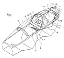
- a front hood is denoted 1 and a second hood 2. Both are manufactured from acrylate resin.
- the front hood is equipped with a first detonation cord 3 extending along the lower edges of the hood and along its topmost part, and the rear hood is in a corresponding manner equipped with a second detonation cord 4.
- the first detonation cord 3 is initiated to detonate in connection with initiation of a powder charge for ejecting the first pilot, through a gas conduit 5 extending to a gas triggered igniter 6 that operates a transmission device 7 activating a charge 8 that initiates a detonation of the first detonation cord 3.
- the rear detonation cord 4 is initiated to detonate in a corresponding manner through a gas conduit 9, a gas triggered igniter 10, a transmission device 11, a charge 12, which initiates detonation of the second detonation cord 4 as well as it initiates an igniter line 13 connected to a pressure switch 14 energizing an electric switch 15.
- An electric impulse is thereby transmitted through an electrical line 16 to an electrical igniter 18 located in a protective balloon container 17 that ignites a gas generator containing sodium azide.
- a protective balloon 19 is instantaneously inflated and fills the space below the rear hood, so that blasted parts thereof, i.e. splinters, are prevented from penetrating into the space below the second hood and injuring the second pilot.
- the protective balloon container 17 is located under the front part of the second hood 2, beneath an oblique pane 20 arranged therein, which during inflation of the protective balloon 19 imposes thereon a motion component directed backwards, below the second hood 2.
- the protective balloon 19 is moreover designed so that it during inflation partly fills the space located backwards, below the second hood 2.
Landscapes
- Business, Economics & Management (AREA)
- Emergency Management (AREA)
- Engineering & Computer Science (AREA)
- Aviation & Aerospace Engineering (AREA)
- Respiratory Apparatuses And Protective Means (AREA)
- Superstructure Of Vehicle (AREA)
- Grinding-Machine Dressing And Accessory Apparatuses (AREA)
- Electrical Discharge Machining, Electrochemical Machining, And Combined Machining (AREA)
- Control And Other Processes For Unpacking Of Materials (AREA)
- Air Bags (AREA)
Abstract
Description
Claims (3)
- The combination of two hoods of a two-seated aircraft and a hood detonation system comprising a detonation cord (3), detonable by means of initiation and attached to the first, front hood (1), and a second detonation cord (4), detonable by means of initiation and attached to the second, rear hood (2),
characterized by
a protective balloon (19) inflatable by initiation of a gas generator essentially simultaneously with the initiation of the detonation of the second detonation cord (4), and adapted to prevent splintered parts from the second hood (2) to move into the space inside the second hood. - The combination according to claim 1,
characterized in
that the gas generator together with the inflatable protective balloon (19) is located below the front part of the second hood (2), beneath an oblique pane (20) arranged therein, which during inflation of the protective balloon imposes thereon a motion component backwards, below the second hood. - The combination according to claim 1 or 2,
characterized in
that the protective balloon (19) is so designed, that it during inflation at least partly fills the space located backwards, below the second hood (2).
Applications Claiming Priority (3)
| Application Number | Priority Date | Filing Date | Title |
|---|---|---|---|
| SE9404441 | 1994-12-21 | ||
| SE9404441A SE502678C2 (en) | 1994-12-21 | 1994-12-21 | Main blast system for two-seater aircraft |
| PCT/SE1995/001447 WO1996019381A1 (en) | 1994-12-21 | 1995-12-01 | Canopy bursting system |
Publications (2)
| Publication Number | Publication Date |
|---|---|
| EP0796197A1 EP0796197A1 (en) | 1997-09-24 |
| EP0796197B1 true EP0796197B1 (en) | 2000-03-29 |
Family
ID=20396410
Family Applications (1)
| Application Number | Title | Priority Date | Filing Date |
|---|---|---|---|
| EP95941950A Expired - Lifetime EP0796197B1 (en) | 1994-12-21 | 1995-12-01 | Canopy bursting system |
Country Status (6)
| Country | Link |
|---|---|
| EP (1) | EP0796197B1 (en) |
| AT (1) | ATE191194T1 (en) |
| DE (1) | DE69516016T2 (en) |
| ES (1) | ES2146323T3 (en) |
| SE (1) | SE502678C2 (en) |
| WO (1) | WO1996019381A1 (en) |
Families Citing this family (2)
| Publication number | Priority date | Publication date | Assignee | Title |
|---|---|---|---|---|
| US5954296A (en) * | 1998-02-18 | 1999-09-21 | Teledyne Industries, Inc. | Aircraft canopy fracture system |
| RU2255878C1 (en) * | 2004-05-24 | 2005-07-10 | Открытое акционерное общество "ОКБ Сухого" | Aircraft canopy opening-closing control system |
Family Cites Families (2)
| Publication number | Priority date | Publication date | Assignee | Title |
|---|---|---|---|---|
| US3281097A (en) * | 1964-12-29 | 1966-10-25 | Tienne Mart E De | Gas operated energy storing actuator |
| US3880387A (en) * | 1974-06-27 | 1975-04-29 | Us Navy | Aircraft canopy ejection |
-
1994
- 1994-12-21 SE SE9404441A patent/SE502678C2/en not_active IP Right Cessation
-
1995
- 1995-12-01 EP EP95941950A patent/EP0796197B1/en not_active Expired - Lifetime
- 1995-12-01 AT AT95941950T patent/ATE191194T1/en active
- 1995-12-01 ES ES95941950T patent/ES2146323T3/en not_active Expired - Lifetime
- 1995-12-01 WO PCT/SE1995/001447 patent/WO1996019381A1/en not_active Ceased
- 1995-12-01 DE DE69516016T patent/DE69516016T2/en not_active Expired - Lifetime
Also Published As
| Publication number | Publication date |
|---|---|
| EP0796197A1 (en) | 1997-09-24 |
| ATE191194T1 (en) | 2000-04-15 |
| WO1996019381A1 (en) | 1996-06-27 |
| SE9404441L (en) | 1995-12-04 |
| SE9404441D0 (en) | 1994-12-21 |
| DE69516016T2 (en) | 2000-09-14 |
| SE502678C2 (en) | 1995-12-04 |
| ES2146323T3 (en) | 2000-08-01 |
| DE69516016D1 (en) | 2000-05-04 |
Similar Documents
| Publication | Publication Date | Title |
|---|---|---|
| US3753576A (en) | Vehicle safety device | |
| US6892621B2 (en) | Mine protection device, particularly for wheeled vehicles | |
| US5791597A (en) | Energy attenuation system | |
| EP1403180A3 (en) | External airbag protection system for helicopters | |
| US5198615A (en) | Fuzing system for tandem demolition warheads | |
| US4823700A (en) | Missile with remote-controlled warhead | |
| US5235128A (en) | Separable missile nosecap | |
| JPH032961B2 (en) | ||
| EP0549659A1 (en) | A device for firing a projectile. | |
| WO2002018205A3 (en) | Inflatable restraint systems for ejection seats | |
| DE3564671D1 (en) | Parachute system and aircraft ejection seat incorporating the same | |
| US4570879A (en) | Pyrotechnical process and device for bailing out of an aircraft | |
| US6591602B1 (en) | Ejection seat rocket motors | |
| EP0796197A1 (en) | Canopy bursting system | |
| EP0491800B1 (en) | A missile weapon system | |
| US4982916A (en) | Ejector seat security device for aircraft | |
| US3361397A (en) | Occupant escape apparatus for aircrafts and the like | |
| US6845947B1 (en) | Aircraft canopy jettison apparatus with airbag | |
| EP0409441B1 (en) | Modular missile upgrade apparatus | |
| US5524543A (en) | Safety priming system for an explosive charge | |
| US3885452A (en) | Rocket catapult aircraft escape arrangement | |
| US8714586B2 (en) | Occupant protection device | |
| GB2356033A (en) | Warhead | |
| EP0390756A3 (en) | Primer for a propellant charge | |
| US3912203A (en) | Rocket catapult aircraft escape arrangement |
Legal Events
| Date | Code | Title | Description |
|---|---|---|---|
| PUAI | Public reference made under article 153(3) epc to a published international application that has entered the european phase |
Free format text: ORIGINAL CODE: 0009012 |
|
| 17P | Request for examination filed |
Effective date: 19970721 |
|
| AK | Designated contracting states |
Kind code of ref document: A1 Designated state(s): AT BE DE ES FR GB IT |
|
| 17Q | First examination report despatched |
Effective date: 19980928 |
|
| RIN1 | Information on inventor provided before grant (corrected) |
Inventor name: VIRGEL AKERMAN Inventor name: OLSSON, GEORG |
|
| RIN1 | Information on inventor provided before grant (corrected) |
Inventor name: AKERMAN VIRGEL Inventor name: HULTIN MATS Inventor name: OLSSON, GEORG |
|
| GRAG | Despatch of communication of intention to grant |
Free format text: ORIGINAL CODE: EPIDOS AGRA |
|
| GRAG | Despatch of communication of intention to grant |
Free format text: ORIGINAL CODE: EPIDOS AGRA |
|
| GRAH | Despatch of communication of intention to grant a patent |
Free format text: ORIGINAL CODE: EPIDOS IGRA |
|
| GRAH | Despatch of communication of intention to grant a patent |
Free format text: ORIGINAL CODE: EPIDOS IGRA |
|
| GRAA | (expected) grant |
Free format text: ORIGINAL CODE: 0009210 |
|
| AK | Designated contracting states |
Kind code of ref document: B1 Designated state(s): AT BE DE ES FR GB IT |
|
| REF | Corresponds to: |
Ref document number: 191194 Country of ref document: AT Date of ref document: 20000415 Kind code of ref document: T |
|
| REF | Corresponds to: |
Ref document number: 69516016 Country of ref document: DE Date of ref document: 20000504 |
|
| ET | Fr: translation filed | ||
| ITF | It: translation for a ep patent filed | ||
| REG | Reference to a national code |
Ref country code: ES Ref legal event code: FG2A Ref document number: 2146323 Country of ref document: ES Kind code of ref document: T3 |
|
| PLBE | No opposition filed within time limit |
Free format text: ORIGINAL CODE: 0009261 |
|
| STAA | Information on the status of an ep patent application or granted ep patent |
Free format text: STATUS: NO OPPOSITION FILED WITHIN TIME LIMIT |
|
| 26N | No opposition filed | ||
| REG | Reference to a national code |
Ref country code: GB Ref legal event code: IF02 |
|
| REG | Reference to a national code |
Ref country code: DE Ref legal event code: R082 Ref document number: 69516016 Country of ref document: DE Representative=s name: PATENTANWAELTE HENKEL, BREUER & PARTNER, DE |
|
| PGFP | Annual fee paid to national office [announced via postgrant information from national office to epo] |
Ref country code: IT Payment date: 20121217 Year of fee payment: 18 Ref country code: ES Payment date: 20121221 Year of fee payment: 18 Ref country code: GB Payment date: 20121220 Year of fee payment: 18 |
|
| PGFP | Annual fee paid to national office [announced via postgrant information from national office to epo] |
Ref country code: AT Payment date: 20121227 Year of fee payment: 18 |
|
| PGFP | Annual fee paid to national office [announced via postgrant information from national office to epo] |
Ref country code: DE Payment date: 20121219 Year of fee payment: 18 Ref country code: FR Payment date: 20130123 Year of fee payment: 18 Ref country code: BE Payment date: 20121218 Year of fee payment: 18 |
|
| BERE | Be: lapsed |
Owner name: *SAAB A.B. Effective date: 20131231 |
|
| REG | Reference to a national code |
Ref country code: DE Ref legal event code: R119 Ref document number: 69516016 Country of ref document: DE |
|
| REG | Reference to a national code |
Ref country code: AT Ref legal event code: MM01 Ref document number: 191194 Country of ref document: AT Kind code of ref document: T Effective date: 20131201 |
|
| GBPC | Gb: european patent ceased through non-payment of renewal fee |
Effective date: 20131201 |
|
| REG | Reference to a national code |
Ref country code: FR Ref legal event code: ST Effective date: 20140829 |
|
| REG | Reference to a national code |
Ref country code: DE Ref legal event code: R119 Ref document number: 69516016 Country of ref document: DE Effective date: 20140701 |
|
| PG25 | Lapsed in a contracting state [announced via postgrant information from national office to epo] |
Ref country code: BE Free format text: LAPSE BECAUSE OF NON-PAYMENT OF DUE FEES Effective date: 20131231 Ref country code: DE Free format text: LAPSE BECAUSE OF NON-PAYMENT OF DUE FEES Effective date: 20140701 |
|
| PG25 | Lapsed in a contracting state [announced via postgrant information from national office to epo] |
Ref country code: AT Free format text: LAPSE BECAUSE OF NON-PAYMENT OF DUE FEES Effective date: 20131201 Ref country code: GB Free format text: LAPSE BECAUSE OF NON-PAYMENT OF DUE FEES Effective date: 20131201 Ref country code: FR Free format text: LAPSE BECAUSE OF NON-PAYMENT OF DUE FEES Effective date: 20131231 |
|
| REG | Reference to a national code |
Ref country code: ES Ref legal event code: FD2A Effective date: 20150327 |
|
| PG25 | Lapsed in a contracting state [announced via postgrant information from national office to epo] |
Ref country code: ES Free format text: LAPSE BECAUSE OF NON-PAYMENT OF DUE FEES Effective date: 20131202 |
|
| PG25 | Lapsed in a contracting state [announced via postgrant information from national office to epo] |
Ref country code: IT Free format text: LAPSE BECAUSE OF NON-PAYMENT OF DUE FEES Effective date: 20131201 |