EP0795799B1 - Image forming apparatus and image forming method - Google Patents
Image forming apparatus and image forming method Download PDFInfo
- Publication number
- EP0795799B1 EP0795799B1 EP97104079A EP97104079A EP0795799B1 EP 0795799 B1 EP0795799 B1 EP 0795799B1 EP 97104079 A EP97104079 A EP 97104079A EP 97104079 A EP97104079 A EP 97104079A EP 0795799 B1 EP0795799 B1 EP 0795799B1
- Authority
- EP
- European Patent Office
- Prior art keywords
- image
- toner image
- toner
- electric charge
- transfer
- Prior art date
- Legal status (The legal status is an assumption and is not a legal conclusion. Google has not performed a legal analysis and makes no representation as to the accuracy of the status listed.)
- Expired - Lifetime
Links
- 238000000034 method Methods 0.000 title claims description 12
- 239000007788 liquid Substances 0.000 claims description 50
- 239000000463 material Substances 0.000 claims description 42
- 238000011144 upstream manufacturing Methods 0.000 claims 1
- 239000002245 particle Substances 0.000 description 66
- 238000007600 charging Methods 0.000 description 27
- 238000010276 construction Methods 0.000 description 5
- 230000005684 electric field Effects 0.000 description 5
- 238000004140 cleaning Methods 0.000 description 4
- 230000008030 elimination Effects 0.000 description 4
- 238000003379 elimination reaction Methods 0.000 description 4
- 239000007787 solid Substances 0.000 description 4
- 230000000694 effects Effects 0.000 description 3
- 239000002344 surface layer Substances 0.000 description 3
- 238000007786 electrostatic charging Methods 0.000 description 1
- 230000009969 flowable effect Effects 0.000 description 1
- 239000010410 layer Substances 0.000 description 1
- 239000000843 powder Substances 0.000 description 1
- 239000002904 solvent Substances 0.000 description 1
Images





Classifications
-
- G—PHYSICS
- G03—PHOTOGRAPHY; CINEMATOGRAPHY; ANALOGOUS TECHNIQUES USING WAVES OTHER THAN OPTICAL WAVES; ELECTROGRAPHY; HOLOGRAPHY
- G03G—ELECTROGRAPHY; ELECTROPHOTOGRAPHY; MAGNETOGRAPHY
- G03G15/00—Apparatus for electrographic processes using a charge pattern
- G03G15/06—Apparatus for electrographic processes using a charge pattern for developing
- G03G15/10—Apparatus for electrographic processes using a charge pattern for developing using a liquid developer
- G03G15/11—Removing excess liquid developer, e.g. by heat
Definitions
- the present invention relates to an on-demand type image forming apparatus and image forming method.
- Fig. 12 As for an on-demand type image forming apparatus for recording an image on a transfer material by an electrophotographic method using a liquid developer, a construction shown in Fig. 12 has been generally employed so far.
- numeral 11 designates an image carrier which is a photosensitive drum and is rotated to the direction shown by an arrow.
- an electrical charging device 12 a light exposing device 13, a developing device 14, a squeezing device 15, a transfer device 16, a cleaning blade 17 and an elimination device 18.
- the electrical charging device 12 is connected to an electric source which is not shown in the figure.
- the transfer device 16 using a corona type electrical charger is connected to an electric source DC.
- a surface (photosensitive surface) of the image carrier 11 is charged, in (+) for example, by the electrical charging device 12 and then light is exposed to the surface of the image carrier 11 by the light exposing device 13 so that an electrostatic latent image 1 is formed on said surface.
- a liquid developer 3 is applied to said surface of the image carrier 11 by the developing device 14 and a toner image 2A is formed on said surface by toner particles 2, of (+) for example, based on the electrostatic latent image 1.
- the liquid developer 3 is a liquid of insulating nature in which toner particles 2 charged in (+) or (-) are dispersed. In the figure, the toner particles 2 are charged in (+).
- the liquid developer 3 is fed onto the electrostatic latent image 1 of the image carrier 11 and development is so made that the toner particles 2 of (+) dispersed in the liquid developer 3 are moved electrophoretically to the electrostatic latent image 1.
- the toner particles 2 remaining on the surface of the image carrier 11 are removed by the cleaning blade 17 and the electric charge remaining on the surface of the image carrier 11 is eliminated by the elimination device 18.
- the toner image 2A after developed, on the surface of the image carrier 11 is in a state that a lot of toner particles 2 are bound and gathered by the electric field caused by the electric charge existing on a non-picture and line portion where no toner image is formed and the cohesive force between the toner particles 2 is weak.
- the toner particles 2 of an edge portion of the toner image 2A existing near the non-picture and line portion are bound to be pressed and held by the edge effect of the electric field caused by the electric charge of the non-picture and line portion.
- the binding force by the electric field caused by the electric charge of the non-picture and line portion does not tend to act on the toner particles 2 in the central portion of the toner image 2A and the toner particles 2 are liable to move.
- the image density of the toner image 2A is increased, a phenomenon that the toner image 2A flows at the time of removing the surplus liquid developer becomes remarkable. That is, if the image density of the toner image 2A is increased, it means that a quantity of solid content in the toner image 2A to be transferred onto the surface of the transfer material 4 is increased, which in turn means that a quantity of the toner adhering to the surface of the image carrier by the development is increased and the toner layer is made thicker.
- Fig. 10 shows steps in which the toner image is formed overlappedly.
- letter A designates an image recording device of a first step
- letter B designates an image recording device of a second step.
- same portions as those shown in Fig. 12 are denoted with same numerals.
- the toner image 2A is formed on the transfer material 4, then in the device B (without fixing the respective color) a toner image 2B in a separate color is printed overlappedly on the previous toner image 2A.
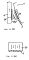
- the matter that the toner image flows at the time of overlapped printing means that there occurs a line-like irregularity in the toner image 2B printed at the latter step or a flow-out of the toner particles 2 beyond a frame of the toner image 2B, as shown in Fig. 11(b).
- a transfer device 16A as shown in Fig. 13 in which a transfer device 16 and an electrical charger 161 which is an electric charge giving portion are aligned in the toner image moving direction (Japanese published patent Sho 63-305375).
- the transfer device 16 gives an electric charge in a reverse polarity as that of the toner particles of a toner image 2A from a back side of a transfer material 4.
- the electrical charger 161 which is the electric charge giving portion gives an electric charge in a same polarity as that of the toner particles 2 of the toner image 2A from the back side of the transfer material so that the toner image is formed pressedly on a photosensitive surface of the image carrier 11 by the repulsive force between the toner particles 2 and the electric charge, thereby irregularity of the image occurring at the time of contact of the transfer material 4 and the toner image 2 is suppressed.
- the electrical charger 16 is a corona type charger.
- the transfer device 16 is connected to an electric source DC.
- a prior art method and apparatus for forming an electrostatic latent image on a photosensitive image carrier, developing the same to a toner image by a liquid developer and transferring the toner image to a transfer material by means of a roller are described in US-A-4 218 246.
- Surplus carrier liquid of the liquid developer is removed from the image carrier by means of a corona charging device arranged between the transferring roller and a liquid developer feeding means and applying a charge of the same polarity as the toner image to the toner image.
- FIG. 1 Another xerographic image forming method and apparatus which has a corona generating device positioned in the path after a developing means containing powder toner particles just before a magnetic toner removal device is described in US-A-3 994 725.
- the corona generating device applies a charge of the same polarity as the toner image to the toner image in order to reduce the background potential.
- An image forming apparatus comprises the features of claim 1.
- the electric charge giving means disposed between the developing means and the surplus liquid developer removing means gives an electric charge directly to the toner image formed on the surface of the image carrier in a same polarity as that of said toner image, thereby the toner image is pressed onto the surface of the image carrier to form a state where the toner particles contact each other densely. Hence, there occurs no flow of the toner image when the step to remove the surplus liquid of the liquid developer on the image carrier, after the development, is taken place.
- the toner image formed on the image carrier is prevented from flowing when the surplus liquid developer is removed, especially the toner image when a dense toner image is formed and when an overlapped printing is made is prevented securely from flowing, and a toner image of high density and high quality can be formed.
- the additional electric charge giving means disposed between the surplus liquid developer removing means and the transfer means gives an electric charge directly to the toner image of the image carrier passing the surplus liquid developer removing means in a same polarity as that of said toner image, thereby the toner image is pressed onto the surface of the image carrier to form a state where the toner particles contact each other densely.
- the toner image can be prevented from flowing when the toner image and the transfer material make contact with each other at t:he time of transfer.
- the transfer means by the transfer means an electric charge of a same polarity as that of the toner particles of the toner image of the image carrier is given, thereby the toner particles are pressed onto the photosensitive surface of the image carrier by the repulsive force between the toner particles and the electric charge so that the toner image is strengthened. Thereafter, an electric charge is given to the toner particles of the toner image from the back side of the transfer material in a reverse polarity of that of the toner particles and the transfer is made onto the transfer material. Thus, the toner image is prevented from flowing by the contact of the transfer material and the toner image.
- An image forming method according to the present invention comprises the steps of Claim 3.
- a preferred embodiment of the method is defined in claim 4.
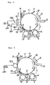
- FIG. 1 An embodiment for explaining certain features of the present invention is described with reference to Figs. 1 and 2.
- This embodiment is designed to be applied to the image forming apparatus shown in Fig. 12 and same portions in Figs. 1 and 2 as those in Fig. 12 are denoted with same numerals.
- numeral 11 designates an image carrier which is rotated to the direction shown by an arrow.
- an electrical charging device 12 a light exposing device 13, a developing device 14, a squeezing device 15, a transfer device 16, a cleaning blade 17 and an elimination device 18.
- Numeral 1 designates an electrostatic latent image
- numeral 2 designates toner particles
- numeral 2A designates a toner image
- numeral 3 designates a liquid developer
- numeral 4 designates a transfer material.
- an electrical charging device 21 between the developing device 14 and the squeezing device 15.
- This electrical charging device 21 is one effective example of electric charge giving means for giving an electric charge directly to the toner image 2A formed on a surface of the image carrier 11 in a same polarity as that of said toner image 2A.
- a corona electrical charging device of a corotron type or a scorotron type is effective.
- the electrical charging device 21 of a corona type is connected to an electric source DC to be applied by a direct current voltage or an alternating current voltage in which direct current is overlapped, and gives an electric charge to the toner image 2A.
- the electrical charging device such as using a needle electrode or a solid discharge electrode can be also employed.
- the liquid developer 3 is a liquid of insulating nature in which toner particles 2 electrically charged in (+) or (-) are dispersed. In the figure, the toner particles 2 are charged in (+).
- the liquid developer 3 is fed onto the electrostatic latent image 1 of the image carrier 11 and development is made so that the toner particles 2 of (+) dispersed in the liquid developer 3 are moved electrophoretically to the electrostatic latent image 1.
- said toner image 2A after developed is given an electric charge e of same polarity as the toner particles 2 by the electrical charging device 21, the toner particles 2 are pressed onto the surface of the image carrier 11 by an electric field formed by the electric charge on the surface of the toner image 2A and become a densely gathered state. Thus, the toner particles 2 are pressed and form a strong toner image 2A.
- the transfer material 4 is carried into contact with the image carrier 11 and an electric charge is given from a back side of the transfer material 4 in a reverse polarity, (-) for example, of that of the toner particles 2 of the toner image 2A by the transfer device 16 and the toner particles 2 forming the toner image 2A on the image carrier 11 are attracted onto the transfer material 4 so that the toner image 2A is transferred onto the transfer material 4.
- the toner particles 2 remaining on the surface of the image carrier 11 are removed by the cleaning blade 17 and the electric charge remaining on the surface of the image carrier 11 is eliminated by the elimination device 18.
- the electrical charging device 21 which is an electric charge giving means, disposed between the developing device 14 and the squeezing device 15 gives an electric charge directly to the toner image 2A formed on the surface of the image carrier 11 in a same polarity as that of said toner image 2A, thereby the toner image 2A is pressed onto the surface of the image carrier 11 and the toner particles 2 become a densely gathered and strong state.
- the toner image 2A formed on the image carrier 11 is prevented from flowing at the time of squeezing, especially the toner image 2A is securely prevented from flowing at the time when the toner image 2A is made in a high density or when an overlapped printing is made on the transfer material 4, and the toner image 2A of high density and high quality can be formed.
- a transfer device 16A in which a transfer device 16 and an electrical charger 161 as an electric charge giving portion are aligned in the toner image moving direction may be used.
- the conventional transfer device 16 gives an electric charge from the back side of the transfer material 4 in a reverse polarity of that of the toner particles of the toner image 2A.
- the electrical charger 161 as the electric charge giving portion gives an electric charge from the back side of the transfer material 4 in a same polarity as that of the toner particles 2 of the toner image 2A and the toner particles 2 are pressed onto a photosensitive surface of the image carrier 11 by the repulsive force between the toner particles 2 and the electric charge, thus irregularity of the image caused by the contact of the transfer material 4 and the toner image 2 is suppressed.
- the electrical charger 161 is a corona electrical charger. In this case, the toner particles of the toner image 2A in the transfer step can also be prevented from flowing.
- a bias roller type transfer device 162 may also be used.
- the bias roller of this transfer device 162 is connected to a direct current electric source DC to apply voltage to the transfer material 4 directly, and by the electric field caused thereby, the toner image 2A is transferred onto the transfer material 4.
- a belt-like or roller-like intermediate transfer member may also be used.
- Fig. 5 shows a case where a belt-like intermediate transfer member is used.
- An endless intermediate transfer belt 23 is supported movably around a pulley 24, which is rotationally driven by a motor M, an intermediate pulley 25 and a transfer roller 26, and this intermediate transfer belt 23 makes contact with a surface of the image carrier 11 at one portion.
- the transfer roller 26, in combination with a transfer roller 27, carries the transfer material 4.
- the pulley 24 is rotated by the motor M and the intermediate transfer belt 23 is moved in the direction shown by arrows.
- the intermediate transfer belt 23 makes contact with the surface of the image carrier 11, is transferred with the toner image 2A formed on said surface and is further carried between the transfer rollers 26 and 27. While the intermediate transfer belt 23 passes between the transfer rollers 26 and 27, it is overlapped on the transfer material 4 which is carried by said transfer rollers 26 and 27 so that the toner image 2A is transferred.
- FIG. 6 The apparatus of Fig. 6 is designed to be applied to the image forming apparatus shown in Fig. 1 and same portions in Fig. 6 as those in Fig. 1 are denoted with same numerals.
- This preferred embodiment comprises, in addition to the electrical charging device 21 in the image forming apparatus of the construction shown in Fig. 1, a transfer device 22, of corona type for example, as an electric charge giving means between the squeezing device 15 and the transfer device 16.
- This electrical charging device 22 of corona type is one effective example of electric charge giving means for giving an electric charge directly to the toner image 2A formed on a surface of the image carrier 11 in a same polarity as that of said toner image 2A, and construction and function thereof is same as the electrical charging device 21 shown in Fig. 1.
- a surface (photosensitive surface) of the image carrier 11 is electrically charged, in (+) for example, by the electrical charging device 12 and then light is exposed to the surface of the image carrier 11 by a light exposing device 13 so that an electrostatic latent image 1 is formed on said surface.
- a liquid developer 3 is applied to the surface of the image carrier 11 by a developing device 14 and the toner image 2A is formed on said surface by the toner particles 2, of (+) for example, based on the electrostatic latent image 1.
- an electric charge is given directly to the toner image 2A formed on the surface of the image carrier 11 in a same polarity, (+) for example, as that of the toner particles 2 of said toner image 2A by the electrical charging device 21.
- the toner particles 2 of the toner image 2A are pressed onto the surface of the image carrier 11 and become a densely gathered state.
- the toner particles 2 are pressed and form a strong toner image 2A.
- the toner image 2A is pressed onto the surface of the image carrier 11 so as to be compressed. That is, before a transfer step, the toner image 2A is pressed to be compressed onto the surface of the image carrier 11. This action to press the toner image 2A onto the surface of the image carrier 11 is same as in the case of the electrical charging device 21.
- the transfer device 16 the toner image 2A on the surface of the image carrier 11 is transferred onto the transfer material 4.
- the toner image 2A is pressed and strengthened by the electrical charging device 22, there occurs no flow of the image.
- the electrical charging device 22 which is an electric charge giving means, disposed between the squeezing device 15 and the transfer device 16 gives an electric charge directly to the toner image 2A of the image carrier 11, before the toner image 2A enters the transfer step, in a same polarity as that of said toner image 2A, thereby the toner image 2A is pressed to be compressed and strengthened onto the surface of the image carrier 11.
- the toner particles 2 can be prevented from flowing.
- the toner image 2A formed on the image carrier 11 is prevented from flowing when the surplus liquid developer is removed and when the transfer is made, especially the toner image when a dense toner image is formed and when an overlapped printing is made is prevented securely from flowing, and a toner image of high density and high quality can be formed.
- a transfer device 16A in which an electrical charging device 161 is added to the transfer device 16 may be used, said electrical charging. device 161 giving an electric charge from a back side of the transfer material 4 in a same polarity as that of the toner particles 2 of the toner image 2A so that the toner particles 2 are pressed onto the photosensitive surface of the image carrier 11 by the repulsive force between the toner particles 2 and the electric charge, thus irregularity of the image caused by the contact of the transfer material 4 and the toner image 2 is suppressed.
- a bias roller type transfer device may be used, as well as such as using a belt-like or roller-like intermediate transfer means may be used.
Landscapes
- Physics & Mathematics (AREA)
- General Physics & Mathematics (AREA)
- Wet Developing In Electrophotography (AREA)
- Electrostatic Charge, Transfer And Separation In Electrography (AREA)
- Ink Jet (AREA)
Description
Claims (4)
- An image forming apparatus comprisingan image carrier (11),a means (12) for forming an electrostatic latent image (1) on a surface of said image carrier (11),a developing means (14) for supplying a liquid developer (3) onto said electrostatic latent image (1) to form a toner image (2A),a means (15) for removing a surplus liquid developer remaining on the surface of said image carrier (11) after said toner image (2A) is formed,a transfer means (16) for transferring said toner image (2A) formed on the surface of said image carrier (11) onto a surface of a transfer material (4),an electric charge giving means (21) disposed between said developing means (14) and said means (15) for removing the surplus liquid developer for giving an electric charge to said toner image (2A) in the same polarity as that of said toner image, andan electric charge giving means (22) disposed between said means (15) for removing the surplus liquid developer and said transfer means (16) for giving an electric charge to said toner image (2A) in the same polarity as that of said toner image (2A).
- An image forming apparatus as claimed in claim 1, wherein said transfer means (16A) comprises two electric charge giving portions aligned along the toner image moving direction, one (161) positioned upstream in the toner image moving direction being for giving an electric charge to said toner image (2A) in the same polarity as that of said toner image (2A) and the other (16) positioned downstream in the toner image moving direction being for giving an electric charge from a back side of said transfer material (4) in a reverse polarity of that of said toner image (2A) so that said toner image (2A) is transferred onto said transfer material (4).
- An image forming method comprising the consecutive steps offorming an electrostatic latent image (1) on a surface of an image carrier (11),supplying a liquid developer (3) onto said electrostatic latent image (1) to form a toner image (2A) on the surface of said image carrier (11),giving an electric charge to said toner image (2A) in the same polarity as that of said toner image (2A),removing a surplus liquid of said liquid developer (3) remaining on the surface of said image carrier (11),giving an electric charge once more to said toner image (2A) in the same polarity as that of said toner image (2A), andtransferring said toner image (2A) on the surface of said image carrier (11) onto a surface of a transfer material (4).
- An image forming method as claimed in claim 3, wherein said step of transfer comprises the steps of giving an electric charge to said toner image (2A) on the surface of said image carrier (11) in the same polarity as that of said toner image (2A) and then giving an electric charge from a back side of said transfer material (4) in the reverse polarity of that of said toner image (2A) so that said toner image (2A) is transferred onto said transfer material (4).
Applications Claiming Priority (3)
| Application Number | Priority Date | Filing Date | Title |
|---|---|---|---|
| JP5641996 | 1996-03-13 | ||
| JP56419/96 | 1996-03-13 | ||
| JP8056419A JPH09244425A (en) | 1996-03-13 | 1996-03-13 | Device and method for image forming |
Publications (2)
| Publication Number | Publication Date |
|---|---|
| EP0795799A1 EP0795799A1 (en) | 1997-09-17 |
| EP0795799B1 true EP0795799B1 (en) | 2002-07-31 |
Family
ID=13026596
Family Applications (1)
| Application Number | Title | Priority Date | Filing Date |
|---|---|---|---|
| EP97104079A Expired - Lifetime EP0795799B1 (en) | 1996-03-13 | 1997-03-11 | Image forming apparatus and image forming method |
Country Status (5)
| Country | Link |
|---|---|
| US (1) | US5835826A (en) |
| EP (1) | EP0795799B1 (en) |
| JP (1) | JPH09244425A (en) |
| DE (1) | DE69714323T2 (en) |
| ES (1) | ES2180836T3 (en) |
Families Citing this family (18)
| Publication number | Priority date | Publication date | Assignee | Title |
|---|---|---|---|---|
| JPH1173025A (en) * | 1997-06-16 | 1999-03-16 | Ricoh Co Ltd | Image forming method, and electrophotographic developer |
| US5974292A (en) * | 1997-10-31 | 1999-10-26 | Xerox Corporation | Liquid ink development dragout control |
| KR100265736B1 (en) * | 1997-12-08 | 2000-09-15 | 윤종용 | Electrophotographic printer |
| US6006061A (en) * | 1998-11-02 | 1999-12-21 | Xerox Corporation | Method and apparatus for forming high quality images in an electrostatic printing machine |
| US6219501B1 (en) * | 2000-03-28 | 2001-04-17 | Xerox Corporation | Method and apparatus for toner cake delivery |
| US6536876B1 (en) | 2002-04-15 | 2003-03-25 | Hewlett-Packard Company | Imaging systems and methods |
| US7169744B2 (en) * | 2002-06-06 | 2007-01-30 | Procter & Gamble Company | Organic catalyst with enhanced solubility |
| US7557076B2 (en) * | 2002-06-06 | 2009-07-07 | The Procter & Gamble Company | Organic catalyst with enhanced enzyme compatibility |
| US20050113246A1 (en) * | 2003-11-06 | 2005-05-26 | The Procter & Gamble Company | Process of producing an organic catalyst |
| JP2006098548A (en) * | 2004-09-28 | 2006-04-13 | Toshiba Corp | Image forming apparatus and image forming method |
| JP4772371B2 (en) * | 2005-04-25 | 2011-09-14 | 株式会社リコー | Image forming apparatus and transferability adjusting method of image forming apparatus |
| AR051659A1 (en) * | 2005-06-17 | 2007-01-31 | Procter & Gamble | A COMPOSITION THAT INCLUDES AN ORGANIC CATALYST WITH IMPROVED ENZYMATIC COMPATIBILITY |
| JP4784736B2 (en) * | 2005-09-27 | 2011-10-05 | セイコーエプソン株式会社 | Image forming apparatus |
| US7760217B1 (en) | 2006-04-28 | 2010-07-20 | Hewlett-Packard Development Company, L.P. | Imaging methods and imaging devices |
| JP4876015B2 (en) * | 2007-04-18 | 2012-02-15 | 大日本スクリーン製造株式会社 | Image forming apparatus, pattern forming system, image forming method, and pattern forming method |
| WO2008129911A1 (en) * | 2007-04-18 | 2008-10-30 | Dainippon Screen Mfg. Co., Ltd. | Image formation device, image formation method, pattern formation system, and pattern formation method |
| JP4834597B2 (en) * | 2007-04-18 | 2011-12-14 | 大日本スクリーン製造株式会社 | Image forming apparatus and image forming method |
| JP2009081381A (en) * | 2007-09-27 | 2009-04-16 | Panasonic Corp | Semiconductor device |
Family Cites Families (9)
| Publication number | Priority date | Publication date | Assignee | Title |
|---|---|---|---|---|
| US4218246A (en) * | 1970-03-18 | 1980-08-19 | Canon Kabushiki Kaisha | Method of electrophotographic recording involving removal of excess developer liquid by corona treatment |
| US3994725A (en) * | 1973-06-18 | 1976-11-30 | Xerox Corporation | Method for enhancing removal of background toner particles |
| US4168119A (en) * | 1974-12-27 | 1979-09-18 | Canon Kabushiki Kaisha | Electrophotographic copying apparatus utilizing liquid developer |
| US4736227A (en) * | 1987-06-01 | 1988-04-05 | Xerox Corporation | Liquid ink transfer system |
| JPH04247472A (en) * | 1991-02-01 | 1992-09-03 | Mitsubishi Heavy Ind Ltd | Electrophotographic printing machine |
| JPH06282175A (en) * | 1993-03-29 | 1994-10-07 | Dainippon Printing Co Ltd | Wet toner transfer device |
| US5424813A (en) * | 1994-05-23 | 1995-06-13 | Xerox Corporation | Apparatus and method for improved blotter roller permeability |
| JPH0830113A (en) * | 1994-07-13 | 1996-02-02 | Toray Ind Inc | Recording apparatus and recording method |
| JP2990675B2 (en) * | 1994-10-24 | 1999-12-13 | 株式会社リコー | Wet image forming device |
-
1996
- 1996-03-13 JP JP8056419A patent/JPH09244425A/en not_active Withdrawn
-
1997
- 1997-03-03 US US08/810,290 patent/US5835826A/en not_active Expired - Fee Related
- 1997-03-11 ES ES97104079T patent/ES2180836T3/en not_active Expired - Lifetime
- 1997-03-11 DE DE69714323T patent/DE69714323T2/en not_active Expired - Fee Related
- 1997-03-11 EP EP97104079A patent/EP0795799B1/en not_active Expired - Lifetime
Also Published As
| Publication number | Publication date |
|---|---|
| JPH09244425A (en) | 1997-09-19 |
| US5835826A (en) | 1998-11-10 |
| ES2180836T3 (en) | 2003-02-16 |
| DE69714323T2 (en) | 2003-03-27 |
| DE69714323D1 (en) | 2002-09-05 |
| EP0795799A1 (en) | 1997-09-17 |
Similar Documents
| Publication | Publication Date | Title |
|---|---|---|
| US5835826A (en) | Image forming apparatus and image forming method | |
| US5826147A (en) | Electrostatic latent image development | |
| JPH01304477A (en) | Developing apparatus free from image sweeping | |
| US6374073B2 (en) | Image forming machine | |
| US4822702A (en) | Method for forming multi-color toner image | |
| EP0887716B1 (en) | Electrostatic latent image development | |
| US5987283A (en) | Apparatus and method for developing an electrostatic latent image directly from an imaging member to a final substrate | |
| JP3346063B2 (en) | Image transfer device | |
| JPH08123207A (en) | Wet image forming device | |
| US5884133A (en) | Electrostatic image transfer apparatus | |
| EP0800120A2 (en) | Method and apparatus for compaction of a liquid ink developed image in a liquid ink type electrostatographic system | |
| US5940665A (en) | Liquid immersion development machine having a multiple zone image development and conditioning apparatus | |
| JPH05307342A (en) | Image forming device | |
| JPH08211687A (en) | Removal of edge irregularity and background by post- developing member | |
| JPH06118842A (en) | Image forming device | |
| JP2001183884A (en) | Imaging system and imaging method for performing one- path multicolor printing for color image | |
| JPH05224565A (en) | Carrier removing device for image forming device | |
| JP3993935B2 (en) | Image forming apparatus | |
| JPH1039705A (en) | Cleaning equipment for electrophotographic equipment | |
| JPS63247781A (en) | image forming device | |
| JP2752886B2 (en) | Toner image transfer device | |
| JPH06258972A (en) | Image recorder | |
| JP6341020B2 (en) | Wet development apparatus and wet image forming apparatus | |
| JP2668228B2 (en) | Color image forming equipment | |
| JP3728382B2 (en) | Wet image forming device |
Legal Events
| Date | Code | Title | Description |
|---|---|---|---|
| PUAI | Public reference made under article 153(3) epc to a published international application that has entered the european phase |
Free format text: ORIGINAL CODE: 0009012 |
|
| 17P | Request for examination filed |
Effective date: 19970408 |
|
| AK | Designated contracting states |
Kind code of ref document: A1 Designated state(s): BE DE ES FR GB IT NL |
|
| 17Q | First examination report despatched |
Effective date: 20000619 |
|
| GRAG | Despatch of communication of intention to grant |
Free format text: ORIGINAL CODE: EPIDOS AGRA |
|
| GRAG | Despatch of communication of intention to grant |
Free format text: ORIGINAL CODE: EPIDOS AGRA |
|
| GRAG | Despatch of communication of intention to grant |
Free format text: ORIGINAL CODE: EPIDOS AGRA |
|
| GRAH | Despatch of communication of intention to grant a patent |
Free format text: ORIGINAL CODE: EPIDOS IGRA |
|
| GRAH | Despatch of communication of intention to grant a patent |
Free format text: ORIGINAL CODE: EPIDOS IGRA |
|
| GRAA | (expected) grant |
Free format text: ORIGINAL CODE: 0009210 |
|
| AK | Designated contracting states |
Kind code of ref document: B1 Designated state(s): BE DE ES FR GB IT NL |
|
| REG | Reference to a national code |
Ref country code: GB Ref legal event code: FG4D |
|
| REF | Corresponds to: |
Ref document number: 69714323 Country of ref document: DE Date of ref document: 20020905 |
|
| ET | Fr: translation filed | ||
| REG | Reference to a national code |
Ref country code: ES Ref legal event code: FG2A Ref document number: 2180836 Country of ref document: ES Kind code of ref document: T3 |
|
| PGFP | Annual fee paid to national office [announced via postgrant information from national office to epo] |
Ref country code: GB Payment date: 20030218 Year of fee payment: 7 |
|
| PGFP | Annual fee paid to national office [announced via postgrant information from national office to epo] |
Ref country code: NL Payment date: 20030317 Year of fee payment: 7 |
|
| PGFP | Annual fee paid to national office [announced via postgrant information from national office to epo] |
Ref country code: FR Payment date: 20030318 Year of fee payment: 7 |
|
| PGFP | Annual fee paid to national office [announced via postgrant information from national office to epo] |
Ref country code: ES Payment date: 20030325 Year of fee payment: 7 |
|
| PGFP | Annual fee paid to national office [announced via postgrant information from national office to epo] |
Ref country code: BE Payment date: 20030326 Year of fee payment: 7 |
|
| PGFP | Annual fee paid to national office [announced via postgrant information from national office to epo] |
Ref country code: DE Payment date: 20030528 Year of fee payment: 7 |
|
| PLBE | No opposition filed within time limit |
Free format text: ORIGINAL CODE: 0009261 |
|
| STAA | Information on the status of an ep patent application or granted ep patent |
Free format text: STATUS: NO OPPOSITION FILED WITHIN TIME LIMIT |
|
| 26N | No opposition filed |
Effective date: 20030506 |
|
| PG25 | Lapsed in a contracting state [announced via postgrant information from national office to epo] |
Ref country code: GB Free format text: LAPSE BECAUSE OF NON-PAYMENT OF DUE FEES Effective date: 20040311 |
|
| PG25 | Lapsed in a contracting state [announced via postgrant information from national office to epo] |
Ref country code: ES Free format text: LAPSE BECAUSE OF NON-PAYMENT OF DUE FEES Effective date: 20040312 |
|
| PG25 | Lapsed in a contracting state [announced via postgrant information from national office to epo] |
Ref country code: BE Free format text: LAPSE BECAUSE OF NON-PAYMENT OF DUE FEES Effective date: 20040331 |
|
| BERE | Be: lapsed |
Owner name: *MITSUBISHI HEAVY INDUSTRIES LTD Effective date: 20040331 |
|
| PG25 | Lapsed in a contracting state [announced via postgrant information from national office to epo] |
Ref country code: NL Free format text: LAPSE BECAUSE OF NON-PAYMENT OF DUE FEES Effective date: 20041001 Ref country code: DE Free format text: LAPSE BECAUSE OF NON-PAYMENT OF DUE FEES Effective date: 20041001 |
|
| GBPC | Gb: european patent ceased through non-payment of renewal fee |
Effective date: 20040311 |
|
| PG25 | Lapsed in a contracting state [announced via postgrant information from national office to epo] |
Ref country code: FR Free format text: LAPSE BECAUSE OF NON-PAYMENT OF DUE FEES Effective date: 20041130 |
|
| NLV4 | Nl: lapsed or anulled due to non-payment of the annual fee |
Effective date: 20041001 |
|
| REG | Reference to a national code |
Ref country code: FR Ref legal event code: ST |
|
| PG25 | Lapsed in a contracting state [announced via postgrant information from national office to epo] |
Ref country code: IT Free format text: LAPSE BECAUSE OF NON-PAYMENT OF DUE FEES;WARNING: LAPSES OF ITALIAN PATENTS WITH EFFECTIVE DATE BEFORE 2007 MAY HAVE OCCURRED AT ANY TIME BEFORE 2007. THE CORRECT EFFECTIVE DATE MAY BE DIFFERENT FROM THE ONE RECORDED. Effective date: 20050311 |
|
| REG | Reference to a national code |
Ref country code: ES Ref legal event code: FD2A Effective date: 20040312 |