EP0795752B1 - Optochemical method and device to determine the concentration of an analyte - Google Patents
Optochemical method and device to determine the concentration of an analyte Download PDFInfo
- Publication number
- EP0795752B1 EP0795752B1 EP96890047A EP96890047A EP0795752B1 EP 0795752 B1 EP0795752 B1 EP 0795752B1 EP 96890047 A EP96890047 A EP 96890047A EP 96890047 A EP96890047 A EP 96890047A EP 0795752 B1 EP0795752 B1 EP 0795752B1
- Authority
- EP
- European Patent Office
- Prior art keywords
- luminescent
- analyte
- luminescence
- layer
- luminescent system
- Prior art date
- Legal status (The legal status is an assumption and is not a legal conclusion. Google has not performed a legal analysis and makes no representation as to the accuracy of the status listed.)
- Expired - Lifetime
Links
Images


Classifications
-
- G—PHYSICS
- G01—MEASURING; TESTING
- G01N—INVESTIGATING OR ANALYSING MATERIALS BY DETERMINING THEIR CHEMICAL OR PHYSICAL PROPERTIES
- G01N21/00—Investigating or analysing materials by the use of optical means, i.e. using sub-millimetre waves, infrared, visible or ultraviolet light
- G01N21/62—Systems in which the material investigated is excited whereby it emits light or causes a change in wavelength of the incident light
- G01N21/63—Systems in which the material investigated is excited whereby it emits light or causes a change in wavelength of the incident light optically excited
- G01N21/64—Fluorescence; Phosphorescence
- G01N21/6428—Measuring fluorescence of fluorescent products of reactions or of fluorochrome labelled reactive substances, e.g. measuring quenching effects, using measuring "optrodes"
-
- G—PHYSICS
- G01—MEASURING; TESTING
- G01N—INVESTIGATING OR ANALYSING MATERIALS BY DETERMINING THEIR CHEMICAL OR PHYSICAL PROPERTIES
- G01N21/00—Investigating or analysing materials by the use of optical means, i.e. using sub-millimetre waves, infrared, visible or ultraviolet light
- G01N21/62—Systems in which the material investigated is excited whereby it emits light or causes a change in wavelength of the incident light
- G01N21/63—Systems in which the material investigated is excited whereby it emits light or causes a change in wavelength of the incident light optically excited
- G01N21/64—Fluorescence; Phosphorescence
- G01N21/645—Specially adapted constructive features of fluorimeters
- G01N21/648—Specially adapted constructive features of fluorimeters using evanescent coupling or surface plasmon coupling for the excitation of fluorescence
-
- G—PHYSICS
- G01—MEASURING; TESTING
- G01N—INVESTIGATING OR ANALYSING MATERIALS BY DETERMINING THEIR CHEMICAL OR PHYSICAL PROPERTIES
- G01N33/00—Investigating or analysing materials by specific methods not covered by groups G01N1/00 - G01N31/00
- G01N33/48—Biological material, e.g. blood, urine; Haemocytometers
- G01N33/50—Chemical analysis of biological material, e.g. blood, urine; Testing involving biospecific ligand binding methods; Immunological testing
- G01N33/53—Immunoassay; Biospecific binding assay; Materials therefor
- G01N33/543—Immunoassay; Biospecific binding assay; Materials therefor with an insoluble carrier for immobilising immunochemicals
- G01N33/54366—Apparatus specially adapted for solid-phase testing
- G01N33/54373—Apparatus specially adapted for solid-phase testing involving physiochemical end-point determination, e.g. wave-guides, FETS, gratings
Definitions
- the invention relates to an optochemical measuring arrangement with a luminescence sensor a biorecognitive layer for measuring the concentration of at least one analyte in a sample, the sensor having at least one island layer, the islands of which are electrical consist of conductive material and the biorecognitive layer on or by means of an intermediate layer is arranged on the island layer, wherein further a first luminescent System is provided which selectively binds the analyte to be measured.
- the invention further relates to a method for measuring the concentration of at least one analyte in a sample.
- Optochemical sensors or optochemical measuring methods are based on the fact that a chemical Response between the optical indicator and the analyte to a change of the optical properties of the sensor.
- a change in the optical properties can, for example, in a change in the absorption or luminescence properties so that the analyte concentration can be detected by spectroscopic methods.
- Optical sensors for measuring chemical substance concentrations are becoming increasingly popular Interest because they have significantly shorter response times compared to conventional greater mechanical robustness and insensitivity to electromagnetic Show interference fields.
- an optochemical sensor has become known from GB-A 2 243 683, which at the end of a fiber optic has a biorecognitive layer that is coated with an analyte a sample can come into contact.
- the biorecognitive layer shows antibodies bound fluorescence-labeled antigens, which on sample contact by the analyte be replaced. The decreasing fluorescence is used as a measure of the analyte concentration detected.
- US Pat. No. 5,449,918 describes an optochemical sensor for continuous determination chemical species described.
- the sensor is based on the use of surface plasmon resonance to amplify the fluorescence radiation chemically selective Membranes, which are applied as a Lang-muir-Blodgett film on island films.
- the island layer is in turn applied to a solid substrate, for example glass.
- WO-A 93 02362 discloses a surface which is used in analytical processes can be.
- the surface contains a metallic island layer as well as a Intermediate layer from a coupling reagent, which covers the island layer and the Molecules such as proteins, nucleic acids, lipids etc. can be bound.
- the islands for example made of silver, have a thickness of 2 to 20 nm and a diameter of up to to 14 nm.
- An assay according to WO-A 93 02362 consists of a partner A, which is linked to a Surface bound, a partner B, which binds to A and a partner C, which for example, is fluorescence-labeled and binds to B. The fluorescence of one at the Island bound molecule increases significantly compared to unbound Molecules.
- WO-A 95 18376 describes a method for determining the concentration of an analyte become known, whereby the analyte is bound to a receptor. After that, two differently labeled ligands added, with one of the ligands specifically on the bound analyte that binds others to unoccupied receptors. From the received relative signals is based on the occupation of the receptors and thus on the concentration of the analyte inferred. Fluorescent markers, e.g. Fluorescein or coumarin can be used.
- the object of the invention is to provide optical measuring arrangements or measuring methods at the outset further described type in such a way that even low substance concentrations of, for example Antibodies or enzymes in a particularly simple and reproducible way can be recorded. Furthermore, the advantageous in optical measuring arrangements, short response time also for the new measuring arrangements or measuring methods to be described to be valid.
- the measuring arrangement according to the invention is characterized above all by the use of two luminescent systems, with at least one of the two systems significantly change optical properties in the vicinity of the island layer.
- the luminophore is not in a chemical bound selective membrane, but a luminescent system selectively binds to measuring analyte, which docks to the biorecognitive layer and thus the luminescent System brings near the island layer, whereby its emission spectrum measurably changes.
- luminophores In conventional luminescence sensors, luminophores have to have a high quantum yield can be used to ensure the necessary sensitivity of the sensor. Do it however, dissolved fluorescent molecules around the sensor have a strong signal background. Therefore, many of these systems need to get a usable signal the excess of dissolved luminophores before the measurement from the actual sensor be removed.
- Two signals can thus be determined from the two luminescent systems, one of which is the contact points of the biorecognitive layer occupied by the analyte and Measured value, which is largely independent of the optical excitation and detection conditions indicates the analyte concentration
- spectral analysis of the emitted luminescent radiation is also possible perform at least one luminescent system and from the spectral changes to conclude on the analyte concentration.
- point d) provides that at least one of the two luminescent systems has a luminophore, the molecules of which have a high spatial density, which leads to strong self-quenching, whereby self-quenching in the vicinity of the island layer is abolished and the emission spectrum at least one of the two luminescent systems changes significantly, or that at least one of the two luminescent systems two spatially closely adjacent molecules which have common excitation and emission spectra, making the spectral distribution of the emission radiation near the island layer significant will be changed
- the island layer can be applied to a transparent surface, which is used for coupling of the excitation beam (e.g. laser or LED) is used.
- the excitation beam e.g. laser or LED
- the evanescent portion of the excitation light be used.
- the configuration can preferably be made such that the islands have a diameter of less than 100 nm, preferably less than 60 nm when using visible Show light.
- the radiation occurs in a preferred measurement geometry of the optochemical measurement arrangement the excitation light from the sample-facing, transparent side of the sensor and the detection of the measurement radiation on the same side.
- the biorecognitive layer on or above the island layer consists of proteins, lipids, lectins, nucleic acids or artificial ligands Proteins such as antibodies, antigens and lectins as well as hormones are preferred. DNA and RNA used. Such biorecognitive layers are characterized by a selective binding of the analyte.
- the two luminescent systems can also preferably proteins, such as antibodies, Antigens and lectins as well as hormones, lipids, DNA and RNA, which with a Luminophore are marked.
- proteins such as antibodies, Antigens and lectins as well as hormones, lipids, DNA and RNA, which with a Luminophore are marked.
- the invention provides that the luminescent systems have at least one luminescence-labeled antibody which is able to bind a detection antibody which binds the actual analyte.
- the table below shows some examples of luminescent systems that interact with certain antibodies in the biorecognitive layer: biorecognit.
- CK creatine kinase
- M muscle and B for brain.
- the design is advantageously made such that the thickness of the immobilized, biorecognitive layer is chosen to be less than 20 nm, in particular less than 15 nm. To increase the luminescence yield, however, the thickness should not be less than 3 to 5 nm, in principle layer thicknesses of 5 to 15 nm can be optimally realized.
- Transition metal complexes are preferably the central atoms ruthenium, platinum and palladium used.
- the island layer used advantageously has a mass thickness of less than 20 nm, preferably less than 15 nm, with a particularly high sensitivity of the island layer an absorption between 40 and 60% for the wavelength of the excitation light used in each case is sought.
- the two luminescent systems can be luminescence-labeled in a variety of ways his.
- at least one of the two luminescent systems can have two have coupled molecules, at least one of which is a luminophore and that other quenches the luminescence of the luminophore, the quenching in the Is removed near the island layer.
- at least one of the two luminescent ones Systems have a luminophore, the molecules of which have a high spatial density which leads to strong self-quenching, with the self-quenching nearby the island layer is removed.
- a particularly advantageous embodiment of the invention provides that at least one of the two luminescent systems has two spatially closely adjacent molecules, which have common excitation and emission spectra, the spectral Significantly change the distribution of the emission radiation near the island layer.
- Spatially closely adjacent molecules that have common excitation and emission spectra are called Exciplex.
- the emission spectrum is a spectral analysis subjected, conclusions being drawn about the analyte concentration via spectral changes can.
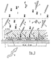
- the optochemical measuring arrangement has a sensor 1, which on one for the excitation and measurement radiation Transparent substrate carries an island layer 2, which consists of a variety of electrically conductive Islands 3, preferably made of gold or silver, are islands 3 Diameters smaller than 300 nm and can for example be evaporated onto the substrate 1, sputtered or produced by electron beam lithographic processes.
- a Biorecognitive layer 4 is directly - or as shown in FIG. 1 - bound via a Spacer or intermediate layer 5 connected to the island layer 2 or in its immediate Environment arranged The biorecognitive layer 4 stands directly or via an analyte-permeable Membrane with sample 7 in connection.
- a first luminescent system 9 is provided in the measuring arrangement Is able to bind analytes 8 selectively, as well as a second, non-analyte-specific, luminescent System 9 *.
- the biorecognitive layer 4 of the sensor can contain both the analyte 8 and also bind the second luminescent system 9 *.
- the two are luminescent Systems 9 and 9 * excited and emit luminescent radiation.
- the quantum yield at least one of the two luminescent systems 9 and 9 * is outside a distance d 15 nm (area of the luminophore / island coupling) low (represented by the Arrows 10 and 11) and increases sharply within the distance d (see arrows 10 'and 11'). It However, it is also possible for at least one of the two luminescent systems 9, 9 * forms an exciplex, d. H. has two spatially closely adjacent molecules, which over have common excitation and emission spectra. The electron spectrum of the Exciplex changes in the vicinity of the island layer, which also changes the emission spectrum changes significantly.
- the intensity of the luminescent radiation of both luminescent Systems 9 and 9 * are detected by a detection device 13, in one device 14 performed a spectral analysis of the emission spectrum or the ratio of the both intensities is determined.
- the ratio obtained or spectral changes are a measure of the concentration of analyte 8 in sample 7.
- the first luminescent system 9 has a biorecognitive molecule, which is labeled with a luminophore, preferably fluorophore F 1 , and which is able to couple to the analyte 8.
- the second luminescent system 9 * has two coupled luminophores or fluorophores A and B, which likewise mark a biorecognitive molecule, which, however, couples directly to the biorecognitive layer 4.
- the second luminescent system 9 * could also have a simple luminescent marking; it would only have to be ensured that the two luminophores are distinguishable for the detection and evaluation device 13, 14 and at least one of the two luminescent systems 9, 9 * undergoes a measurable change in the vicinity of the island layer.
- the coupling between the two luminophores A and B in the vicinity of the island layer could be canceled, as a result of which the luminescence quenching ceases to increase the intensity of the luminescence radiation (see arrow 11).
- luminescence amplification can also occur in the vicinity of the island layer 4, but a luminophore F 1 could also be used, the intensity of which does not change in the vicinity of the island layer, in which case the luminescent system 9 is used only as a reference variable would.
- the first luminescent system 9 consists of two coupled luminophores F 2 and F 3 , and the second luminescent system 9 * with a luminophore C. is marked
- the luminescent system 9 consists of a plurality of luminophores F 4 , which have a spatial density which leads to strong self-quenching. The self-quenching is canceled within the distance d (area of the luminophore, island coupling), so that the intensity of the luminescent radiation increases.
- d area of the luminophore, island coupling
- the first luminescent system 9 consists of a labeled antibody 15, which is attached to the analyte 8 via a detection antibody 16 docks.
- a similar construction is also possible for the second luminescent system 9 *, wherein the detection antibody or reference antibody via at least one luminescence-labeled Antibody has and docked directly to the biorecognitive layer 4.
Description
Die Erfindung betrifft eine optochemische Messanordnung mit einem Lumineszenzsensor mit einer biorekognitiven Schicht zur Messung der Konzentration zumindest eines Analyten in einer Probe, wobei der Sensor zumindest eine Inselschicht aufweist, deren Inseln aus elektrisch leitendem Material bestehen und die biorekognitive Schicht auf oder mittels einer Zwischenschicht an der Inselschicht angeordnet ist, wobei weiters ein erstes lumineszierendes System vorgesehen ist, welches den zu messenden Analyten selektiv bindet. Die Erfindung betrifft weiters ein Verfahren zur Messung der Konzentration zumindest eines Analyten in einer Probe.The invention relates to an optochemical measuring arrangement with a luminescence sensor a biorecognitive layer for measuring the concentration of at least one analyte in a sample, the sensor having at least one island layer, the islands of which are electrical consist of conductive material and the biorecognitive layer on or by means of an intermediate layer is arranged on the island layer, wherein further a first luminescent System is provided which selectively binds the analyte to be measured. The invention further relates to a method for measuring the concentration of at least one analyte in a sample.
Optochemische Sensoren bzw. optochemische Messverfahren basieren darauf, dass eine chemische Reaktion zwischen dem optischen Indikator und dem Analyten zu einer Veränderung der optischen Eigenschaften des Sensors führt. Eine Veränderung der optischen Eigenschaften kann beispielsweise in einer Änderung der Absorptions- bzw. der Lumineszenzeigenschaften liegen, sodass die Analytkonzentration durch spektroskopische Methoden nachweisbar wird.Optochemical sensors or optochemical measuring methods are based on the fact that a chemical Response between the optical indicator and the analyte to a change of the optical properties of the sensor. A change in the optical properties can, for example, in a change in the absorption or luminescence properties so that the analyte concentration can be detected by spectroscopic methods.
Optische Sensoren zur Messung chemischer Stoffkonzentrationen gewinnen zunehmend an Interesse, da sie gegenüber herkömmlichen Messeinrichtungen wesentlich kürzere Ansprechzeiten, eine größere mechanische Robustheit und eine Unempfindlichkeit gegenüber elektromagnetischen Störfeldern aufweisen.Optical sensors for measuring chemical substance concentrations are becoming increasingly popular Interest because they have significantly shorter response times compared to conventional greater mechanical robustness and insensitivity to electromagnetic Show interference fields.
Aus der GB-A 2 243 683 ist beispielsweise ein optochemischer Sensor bekannt geworden, welcher am Ende einer Fiberoptik eine biorekognitive Schicht aufweist, die mit einem Analyten einer Probe in Kontakt treten kann. Die biorekognitive Schicht weist an Antikörpern gebundene fluoreszenzmarkierte Antigene auf, welche bei Probenkontakt durch den Analyten ersetzt werden. Die abnehmende Fluoreszenz wird als Maß für die Analytkonzentration detektiert.For example, an optochemical sensor has become known from GB-A 2 243 683, which at the end of a fiber optic has a biorecognitive layer that is coated with an analyte a sample can come into contact. The biorecognitive layer shows antibodies bound fluorescence-labeled antigens, which on sample contact by the analyte be replaced. The decreasing fluorescence is used as a measure of the analyte concentration detected.
In der US-A 5 449 918 wird ein optochemischer Sensor zur kontinuierlichen Bestimmung chemischer Spezies beschrieben. Der Sensor basiert auf der Verwendung der Surface-Plasmon-Resonance zur Verstärkung der Fluoreszenzstrahlung chemisch selektiver Membranen, welche als Lang-muir-Blodgett Film auf Inselfilme aufgetragen werden. Die Inselschicht ist ihrerseits auf einem festen Substrat, beispielsweise Glas, aufgetragen.US Pat. No. 5,449,918 describes an optochemical sensor for continuous determination chemical species described. The sensor is based on the use of surface plasmon resonance to amplify the fluorescence radiation chemically selective Membranes, which are applied as a Lang-muir-Blodgett film on island films. The The island layer is in turn applied to a solid substrate, for example glass.
Die WO-A 93 02362 offenbart eine Oberfläche, welche in analytischen Prozessen eingesetzt werden kann. Die Oberfläche beinhaltet eine metallische Inselschicht sowie eine Zwischenschicht aus einem Kupplungsreagenz, welche die Inselschicht bedeckt und and die Moleküle wie Proteine, Nukleinsäuren, Lipide etc. gebunden werden können. Die Inseln, beispielsweise aus Silber, haben eine Dicke von 2 bis 20 nm und einen Durchmesser von bis zu 14 nm. Ein Assay gemäß WO-A 93 02362 besteht aus einem Partner A, der an eine Oberfläche gebunden ist, einem Partner B, welcher an A bindet und einem Partner C, welcher beispielsweise fluoreszenzmarkiert ist und an B bindet. Die Fluoreszenz eines an die Inselschicht gebundenen Moleküls erhöht sich signifikant im Vergleich zu ungebundenen Molekülen.WO-A 93 02362 discloses a surface which is used in analytical processes can be. The surface contains a metallic island layer as well as a Intermediate layer from a coupling reagent, which covers the island layer and the Molecules such as proteins, nucleic acids, lipids etc. can be bound. The islands, for example made of silver, have a thickness of 2 to 20 nm and a diameter of up to to 14 nm. An assay according to WO-A 93 02362 consists of a partner A, which is linked to a Surface bound, a partner B, which binds to A and a partner C, which for example, is fluorescence-labeled and binds to B. The fluorescence of one at the Island bound molecule increases significantly compared to unbound Molecules.
Aus der WO-A 95 18376 ist ein Verfahren zur Bestimmung der Konzentration eines Analyten bekannt geworden, wobei der Analyt an einen Rezeptor gebunden wird. Danach werden zwei unterschiedlich markierte Liganden zugesetzt, wobei einer der Liganden spezifisch an den gebundenen Analyten, der andere an unbesetzte Rezeptoren bindet. Aus den dabei erhaltenen relativen Signalen wird auf die Besetzung der Rezeptoren und damit auf die Konzentration des Analyten rückgeschlossen. Dabei können fluoreszierende Marker, wie z.B. Fluorescein oder Coumarin verwendet werden.WO-A 95 18376 describes a method for determining the concentration of an analyte become known, whereby the analyte is bound to a receptor. After that, two differently labeled ligands added, with one of the ligands specifically on the bound analyte that binds others to unoccupied receptors. From the received relative signals is based on the occupation of the receptors and thus on the concentration of the analyte inferred. Fluorescent markers, e.g. Fluorescein or coumarin can be used.
Schwierigkeiten ergeben sich bei den bekannten Messanordnungen bzw. Messverfahren dadurch, dass oft Probleme mit erhöhter Hintergrundstrahlung bzw. nicht stabilen Messsignalen aufgrund sich ändernder optischer Anregungs- und Messbedingungen bzw. alternder Sensorbestandteile auftreten.Difficulties arise with the known measuring arrangements and measuring methods due to the fact that there are often problems with increased background radiation or unstable measurement signals due to changing optical excitation and measurement conditions or aging Sensor components occur.
Aufgabe der Erfindung ist es, optische Messanordnungen bzw. Messverfahren der eingangs beschriebenen Art derart weiterzubilden, dass bereits geringe Stoffkonzentrationen von beispielsweise Antikörpern oder Enzyme in besonders einfacher und reproduzierbarer Weise erfasst werden können. Weiters soll dabei die bei optischen Messanordnungen vorteilhafte, geringe Ansprechzeit auch für die zu beschreibenden, neuen Messanordnungen bzw. Messverfahren gültig sein.The object of the invention is to provide optical measuring arrangements or measuring methods at the outset further described type in such a way that even low substance concentrations of, for example Antibodies or enzymes in a particularly simple and reproducible way can be recorded. Furthermore, the advantageous in optical measuring arrangements, short response time also for the new measuring arrangements or measuring methods to be described to be valid.
Diese Aufgabe wird erfindungsgemäß dadurch gelöst, dass die biorekognitive Schicht sowohl den zu messenden Analyten sowie ein zweites der Probe zusetzbares oder im Sensor vorliegendes lumineszierendes System zumindest indirekt zu binden vermag, wobei sich das Emissionsspektrum zumindest eines der beiden lumineszierenden Systeme in der Nähe der Inselschicht signifikant ändert, derart,
- dass entweder zumindest eines der beiden lumineszierenden Systeme zwei gekoppelte Moleküle aufweist, von welchen zumindest eines ein Luminophor ist und das andere die Lumineszenz des Luminophors löscht, wobei die Lumineszenzlöschung in der Nähe der Inselschicht aufgehoben ist;
- oder dass zumindest eines der beiden lumineszierenden Systeme einen Luminophor aufweist, dessen Moleküle eine hohe räumliche Dichte aufweisen, welche zu starker Eigenquenchung führt, wobei die Eigenquenchung in der Nähe der Inselschicht aufgehoben ist;
- oder dass zumindest eines der beiden lumineszierenden Systeme zwei räumlich eng benachbarte Moleküle aufweist, welche über gemeinsame Anregungs- und Emissionsspektren verfügen, wobei sich die spektrale Verteilung der Emissionsstrahlung in der Nähe der Inselschicht signifikant ändern; sowie dass eine Einrichtung zur Erfassung der Intensität der Lumineszenzstrahlung beider lumineszierender Systeme vorgesehen ist.
- that either at least one of the two luminescent systems has two coupled molecules, at least one of which is a luminophore and the other quenches the luminescence of the luminophore, the quenching of the luminescence in the vicinity of the island layer being canceled;
- or that at least one of the two luminescent systems has a luminophore, the molecules of which have a high spatial density, which leads to strong self-quenching, the self-quenching in the vicinity of the island layer being eliminated;
- or that at least one of the two luminescent systems has two spatially closely adjacent molecules which have common excitation and emission spectra, the spectral distribution of the emission radiation in the vicinity of the island layer changing significantly; and that a device for detecting the intensity of the luminescent radiation of both luminescent systems is provided.
Die erfindungsgemäße Messanordnung zeichnet sich vor allem durch die Verwendung von zwei lumineszierenden Systemen aus, wobei sich bei zumindest einem der beiden Systeme die optischen Eigenschaften in der Nähe der Inselschicht signifikant ändern. Zum Unterschied zur eingangs genannten US-A 5 449 918 befindet sich der Luminophor nicht in einer chemisch selektiven Membran gebunden, sondern ein lumineszierendes System bindet selektiv den zu messenden Analyten, welcher an der biorekognitiven Schicht andockt und so das lumineszierende System in die Nähe der Inselschicht bringt, wodurch sich dessen Emissionsspektrum messbar ändert.The measuring arrangement according to the invention is characterized above all by the use of two luminescent systems, with at least one of the two systems significantly change optical properties in the vicinity of the island layer. In contrast to US-A 5 449 918 mentioned above, the luminophore is not in a chemical bound selective membrane, but a luminescent system selectively binds to measuring analyte, which docks to the biorecognitive layer and thus the luminescent System brings near the island layer, whereby its emission spectrum measurably changes.
In konventionellen Lumineszenzsensoren müssen Luminophore mit hoher Quantenausbeute eingesetzt werden, um die nötige Empfindlichkeit des Sensors zu gewährleisten. Dabei bewirken jedoch gelöste fluoreszierende Moleküle in der Umgebung des Sensors einen starken Signalhintergrund. Daher muss bei vielen dieser Systeme zur Erlangung eines brauchbaren Signals der Überschuss an gelösten Luminophoren vor der Messung vom eigentlichen Sensor entfernt werden.In conventional luminescence sensors, luminophores have to have a high quantum yield can be used to ensure the necessary sensitivity of the sensor. Do it however, dissolved fluorescent molecules around the sensor have a strong signal background. Therefore, many of these systems need to get a usable signal the excess of dissolved luminophores before the measurement from the actual sensor be removed.
Ein erfindungsgemäßes Verfahren zur Messung der Konzentration zumindest eines Analyten
in einer Probe zeichnet sich somit dadurch aus,
Von den beiden lumineszierenden Systemen können somit zwei Signale ermittelt werden, wovon eines die durch den Analyten besetzten Kontaktstellen der biorekognitiven Schicht und Messwert, welcher weitgehend unabhängig von den optischen Anregungs- und Detektionsbedingungen auf die Analytkonzentration schließen lässtTwo signals can thus be determined from the two luminescent systems, one of which is the contact points of the biorecognitive layer occupied by the analyte and Measured value, which is largely independent of the optical excitation and detection conditions indicates the analyte concentration
Es ist jedoch auch möglich eine Spektralanalyse der emittierten Lumineszenzstrahlung zumindest eines lumineszierenden Systems durchzuführen und aus den spektralen Änderungen auf die Analytkonzentration zu schließen.However, spectral analysis of the emitted luminescent radiation is also possible perform at least one luminescent system and from the spectral changes to conclude on the analyte concentration.
In einer Variante des erfindungsgemäßen Verfahrens ist in Punkt d) vorgesehen, dass zumindest eines der beiden lumineszierenden Systeme einen Luminophor aufweist, dessen Moleküle eine hohe räumliche Dichte aufweisen, welche zu starker Eigenquenchung führt, wobei die Eigenquenchung in der Nähe der Inselschicht aufgehoben wird und sich das Emissionsspektrum zumindest eines der beiden lumineszierenden Systeme signifikant ändert, oder dass zumindest eines der beiden lumineszierenden Systeme zwei räumlich eng benachbarte Moleküle aufweist, welche über gemeinsame Anregungs- und Emissionsspektren verfügen, wodurch die spektrale Verteilung der Emissionsstrahlung in der Nähe der Inselschicht signifikant geändert wirdIn a variant of the method according to the invention, point d) provides that at least one of the two luminescent systems has a luminophore, the molecules of which have a high spatial density, which leads to strong self-quenching, whereby self-quenching in the vicinity of the island layer is abolished and the emission spectrum at least one of the two luminescent systems changes significantly, or that at least one of the two luminescent systems two spatially closely adjacent molecules which have common excitation and emission spectra, making the spectral distribution of the emission radiation near the island layer significant will be changed
Es hat sich gezeigt, dass die charakteristischen Messeffekte bei einem Lumineszenzsensor der erfindungsgemäßen optochemischen Messanordnung nur im Bereich der energetischen Kopplung (weniger als 20 nm Abstand) der optisch aktiven Luminophore mit der Inselschicht auftreten- Durch die erfindungsgemäße Ausgestaltung mit überaus dünnen Sensorschichten kann ein entsprechend kurzer Diffusionsweg vorgegeben und dadurch die Ansprechzeit des Sensors entsprechend verkürzt werden Mit konventionellen interferometrischen oder Surface Plasmon Resonance-Methoden lassen sich hingegen geringfügige chemische Änderungen in dünnen Schichten nur mit großem messtechnischem Aufwand erfassen.It has been shown that the characteristic measurement effects in a luminescence sensor optochemical measuring arrangement according to the invention only in the field of energetic Coupling (less than 20 nm distance) of the optically active luminophores with the island layer Due to the configuration according to the invention with extremely thin sensor layers can be given a correspondingly short diffusion path and thereby the response time of the Sensors can be shortened accordingly with conventional interferometric or surface Plasmon resonance methods, however, can see minor chemical changes in Detect thin layers only with great metrological effort.
Weiters kann beispielsweise zur Anregung der ersten und zweiten lumineszierenden Systeme die Inselschicht auf einer transparenten Oberfläche aufgebracht sein, welche zur Einkopplung des Anregungsstrahles (z. B. Laser oder LED) verwendet wird. Zur Anregung kann dabei - wie an sich aus der WO-A 90 06503 bekannt - der evaneszente Anteil des Anregungslichtes verwendet werden.Furthermore, for example, to excite the first and second luminescent systems the island layer can be applied to a transparent surface, which is used for coupling of the excitation beam (e.g. laser or LED) is used. As a suggestion, as known per se from WO-A 90 06503 - the evanescent portion of the excitation light be used.
Besonders starke Änderungen des Emissionsspektrums treten dann auf, wenn die Inseln einen Durchmesser aufweisen, welcher deutlich kleiner als die Wellenlänge der Anregungsstrahlung ist und das Absorptionsminimum mit dem Emissionsmaximum des Luminophors überlappt. Bevorzugt kann hierbei die Ausgestaltung so getroffen werden, dass die Inseln einen Durchmesser von kleiner 100 nm, vorzugsweise kleiner 60 nm bei Verwendung von sichtbarem Licht aufweisen.Particularly strong changes in the emission spectrum occur when the islands join Have diameter which is significantly smaller than the wavelength of the excitation radiation is and the absorption minimum overlaps with the emission maximum of the luminophore. The configuration can preferably be made such that the islands have a diameter of less than 100 nm, preferably less than 60 nm when using visible Show light.
Obwohl sich prinzipiell viele Metalle (z. B. auch Aluminium, Nickel und Kupfer) für die Ausbildung der Inselschicht eignen, können vorteilhafterweise nur jene eingesetzt werden, die auch den chemischen Angriffen des Messmediums standhalten. Dazu zählen vor allem Gold und Silber, welche sich darüber hinaus durch besonders vorteilhafte Absorptionseigenschaften und damit verbundene Erhöhung des Messeffektes auszeichnen.Although in principle many metals (e.g. also aluminum, nickel and copper) are suitable for the Formation of the island layer can be used advantageously only those who also withstand the chemical attacks of the measuring medium. Above all, this includes gold and silver, which are also characterized by particularly advantageous absorption properties and the associated increase in the measuring effect.
In einer bevorzugten Messgeometrie der optochemischen Messanordnung erfolgt die Einstrahlung des Anregungslichtes von der probenabgewandten, transparenten Seite des Sensors und die Detektion der Messstrahlung auf derselben Seite.The radiation occurs in a preferred measurement geometry of the optochemical measurement arrangement the excitation light from the sample-facing, transparent side of the sensor and the detection of the measurement radiation on the same side.
Erfindungsgemäß ist vorgesehen, dass die biorekognitive Schicht an oder über der Inselschicht aus Proteinen, Lipiden, Lektinen, Nukleinsäuren oder artifiziellen Liganden besteht Bevorzugt werden dabei Proteine, wie Antikörper, Antigene und Lektine sowie Hormone, DNA und RNA eingesetzt Derartige biorekognitive Schichten zeichnen sich durch eine selektive Bindung des Analyten aus.According to the invention, it is provided that the biorecognitive layer on or above the island layer consists of proteins, lipids, lectins, nucleic acids or artificial ligands Proteins such as antibodies, antigens and lectins as well as hormones are preferred. DNA and RNA used. Such biorecognitive layers are characterized by a selective binding of the analyte.
Auch die beiden lumineszierenden Systeme können bevorzugt Proteine, wie Antikörper, Antigene und Lektine sowie Hormone, Lipide, DNA und RNA aufweisen, welche mit einem Luminophor markiert sind.The two luminescent systems can also preferably proteins, such as antibodies, Antigens and lectins as well as hormones, lipids, DNA and RNA, which with a Luminophore are marked.
Beispielsweise ist es erfindungsgemäß vorgesehen, dass die lumineszierenden Systeme über
zumindest einen lumineszenzmarkierten Antikörper verfügen, welcher einen den eigentlichen
Analyten bindenden Detektionsantikörper zu binden vermag. In der untenstehenden Tabelle
sind einige Beispiele für lumineszierende Systeme, welche mit bestimmten Antikörpern der
biorekognitiven Schicht zusammenwirken, dargestellt:
In der Tabelle steht CK für Creatinkinase, M für Muscle und B für Brain.
Um eine hinreichend rasche Ansprechzeit und gleichzeitig auch eine ausgeprägte Erhöhung
der Lumineszenzintensität zu gewährleisten, wird mit Vorteil die Ausbildung so getroffen,
dass die Dicke der immobilisierten, biorekognitiven Schicht kleiner als 20 nm, insbesondere
kleiner als 15 nm gewählt wird. Zur Erhöhung der Lumineszenzausbeute soll die Dicke
jedoch nicht unter 3 bis 5 nm betragen wobei prinzipiell Schichtdicken von 5 bis 15 nm optimal
realisierbar sind.In the table, CK stands for creatine kinase, M for muscle and B for brain.
In order to ensure a sufficiently rapid response time and at the same time a pronounced increase in the luminescence intensity, the design is advantageously made such that the thickness of the immobilized, biorecognitive layer is chosen to be less than 20 nm, in particular less than 15 nm. To increase the luminescence yield, however, the thickness should not be less than 3 to 5 nm, in principle layer thicknesses of 5 to 15 nm can be optimally realized.
Erfindungsgemäß ist vorgesehen, dass die beiden lumineszierenden Systeme zumindest einen Fluorophor aus der Gruppe der Triphenylmethanfarbstoffe sowie der homo- und heterozyklischen, aromatischen Kohlenwasserstoffe aufweisen, vorzugsweise
- Amino-Triphenylmethanfarbstoffe: Malachitgrün, Fuchsin, Kristallviolett;
- Phthaleine: Fluorescein, Eosin
- homozyklische, aromatische Kohlenwasserstoffe: Pyrene, Perylene, Benzo(ghi)perylene, Coronene, Anthracene, Phenanthrene;
- heterozyklische, aromatische Kohlenwasserstoffe: Coumarine, Acridine, Carbazole, Qinoline, Triphenylamine, Imidazole, Porphyrine und -ketone, Übergangsmetallkomplexe mit Diimine-Liganden.
- Amino triphenylmethane dyes: malachite green, fuchsine, crystal violet;
- Phthalein: fluorescein, eosin
- homocyclic, aromatic hydrocarbons: pyrene, perylene, benzo (ghi) perylene, coronene, anthracene, phenanthrene;
- heterocyclic, aromatic hydrocarbons: coumarins, acridines, carbazoles, quinolines, triphenylamines, imidazoles, porphyrins and ketones, transition metal complexes with diimine ligands.
Diese Verbindungen können in substituierter oder unsubstituierter Form vorliegen. Bei den Übergangsmetallkomplexen werden bevorzugt die Zentralatome Ruthenium, Platin und Palladium verwendet.These compounds can be in substituted or unsubstituted form. Both Transition metal complexes are preferably the central atoms ruthenium, platinum and palladium used.
Die verwendete Inselschicht weist vorteilhafterweise eine Massendicke kleiner 20 nm, vorzugsweise kleiner 15 nm auf, wobei für eine besonders hohe Empfindlichkeit der Inselschicht eine Absorption zwischen 40 und 60 % für die jeweils verwendete Wellenlänge des Anregungslichtes angestrebt wird.The island layer used advantageously has a mass thickness of less than 20 nm, preferably less than 15 nm, with a particularly high sensitivity of the island layer an absorption between 40 and 60% for the wavelength of the excitation light used in each case is sought.
Die beiden lumineszierenden Systeme können auf vielfaltige Art und Weise lumineszenzmarkiert sein. So kann beispielsweise zumindest eines der beiden lumineszierenden Systeme zwei gekoppelte Moleküle aufweisen, von welchen zumindest eines ein Luminophor ist und das andere die Lumineszenz des Luminophors löscht, wobei die Lumineszenzlöschung in der Nähe der Inselschicht aufgehoben ist. Weiters kann zumindest eines der beiden lumineszierenden Systeme einen Luminophor aufweisen, dessen Moleküle eine hohe räumliche Dichte aufweist, welche zu starker Eigenquenchung fuhrt, wobei die Eigenquenchung in der Nähe der Inselschicht aufgehoben ist.The two luminescent systems can be luminescence-labeled in a variety of ways his. For example, at least one of the two luminescent systems can have two have coupled molecules, at least one of which is a luminophore and that other quenches the luminescence of the luminophore, the quenching in the Is removed near the island layer. Furthermore, at least one of the two luminescent ones Systems have a luminophore, the molecules of which have a high spatial density which leads to strong self-quenching, with the self-quenching nearby the island layer is removed.
Eine besonders vorteilhafte Ausgestaltung der Erfindung sieht vor, dass zumindest eines der beiden lumineszierenden Systeme zwei räumlich eng benachbarte Moleküle aufweist, welche über gemeinsame Anregungs- und Emissionsspektren verfügen, wobei sich die spektrale Verteilung der Emissionsstrahlung in der Nähe der Inselschicht signifikant ändern. Räumlich eng benachbarte Moleküle, welche über gemeinsame Anregungs- und Emissionsspektren verfügen, werden als Exciplex bezeichnet. Das Emissionsspektrum wird einer Spektralanalyse unterzogen, wobei über spektrale Änderungen auf die Analytkonzentration geschlossen werden kann.A particularly advantageous embodiment of the invention provides that at least one of the two luminescent systems has two spatially closely adjacent molecules, which have common excitation and emission spectra, the spectral Significantly change the distribution of the emission radiation near the island layer. Spatially closely adjacent molecules that have common excitation and emission spectra, are called Exciplex. The emission spectrum is a spectral analysis subjected, conclusions being drawn about the analyte concentration via spectral changes can.
Die Erfindung wird im folgenden anhand von schematischen Zeichnungen näher erläutert.The invention is explained in more detail below with the aid of schematic drawings.
Es zeigen:
In dem in Fig. 1 dargestellten Beispiel weist die erfindungsgemäße optochemische Messanordnung
einen Sensor 1 auf, welcher auf einem für die Anregungs- und Messstrahlung
transparenten Substrat eine Inselschicht 2 trägt, die aus einer Vielzahl von elektrisch leitendenden
Inseln 3, vorzugsweise aus Gold oder Silber, besteht Die Inseln 3 haben einen
Durchmesser kleiner als 300 nm und können beispielsweise auf das Substrat 1 aufgedampft,
aufgesputtert oder durch elektronenstrahllithographische Verfahren hergestellt werden. Eine
biorekognitive Schicht 4 ist direkt - oder wie in Fig. 1 dargestellt - gebunden über eine
Spacer- oder Zwischenschicht 5 mit der Inselschicht 2 verbunden bzw. in deren unmittelbarer
Umgebung angeordnet Die biorekognitive Schicht 4 steht direkt oder über eine analytpermeable
Membran mit der Probe 7 in Verbindung.In the example shown in FIG. 1, the optochemical measuring arrangement according to the invention has
a
In der Messanordnung ist ein erstes lumineszierendes System 9 vorgesehen, welches den
Analyten 8 selektiv zu binden vermag, sowie ein zweites nicht analytspezifisches, lumineszierendes
System 9*. Die biorekognitive Schicht 4 des Sensors kann sowohl den Analyten 8 als
auch das zweite lumineszierende System 9* binden. Innerhalb der Distanz D, der Eindringtiefe
des evaneszenten Anteiles des Anregungslichtes 12, werden die beiden lumineszierenden
Systeme 9 und 9* angeregt und emittieren Lumineszenzstrahlung. Die Quantenausbeute
zumindest eines der beiden lumineszierenden Systeme 9 und 9* ist außerhalb einer Distanz d
von ca. 15 nm (Bereich der Luminophor/Insel-Kopplung) gering (dargestellt durch die
Pfeile 10 und 11) und erhöht sich innerhalb der Distanz d stark (siehe Pfeile 10' und 11'). Es
ist jedoch auch möglich, dass zumindest eines der beiden lumineszierenden Systeme 9, 9*
einen Exciplex bildet, d. h. zwei räumlich eng benachbarte Moleküle aufweist, welche über
gemeinsame Anregungs- und Emissionsspektren verfügen. Das Elektronenspektrum des
Exciplex verändert sich in der Nähe der Inselschicht wodurch sich auch das Emissionsspektrum
signifikant ändert. Die Intensität der Lumineszenzstrahlung beider lumineszierender
Systeme 9 und 9* wird von einer Detektionseinrichtung 13 erfasst, wobei in einer Einrichtung
14 eine Spektralanalyse des Emissionsspektrums durchgeführt oder das Verhältnis der
beiden Intensitäten ermittelt wird. Die gewonnene Verhältniszahl bzw. spektrale Änderungen
sind ein Maß für die Konzentration des Analyten 8 in der Probe 7.A first
Im dargestellten Beispiel gemäß Fig. 1 weist das erste lumineszierende System 9 ein mit
einem Luminophor vorzugsweise Fluorophor F1 markiertes biorekognitives Molekül auf,
welches in der Lage ist, an den Analyten 8 anzukoppeln. Das zweite lumineszierende System
9* verfügt über zwei gekoppelte Luminophore oder Fluorophore A und B, welche ebenfalls
ein biorekognitives Molekül markieren, welches jedoch direkt an der biorekognitiven
Schicht 4 ankoppelt. Anstelle des gekoppelten Systems der Luminophore A und B könnte
auch das zweite lumineszierende System 9* eine einfache Lumineszenzmarkierung aufweisen,
es müsste lediglich sichergestellt sein, dass die beiden Luminophore für die Detektions-
und Auswerteeinrichtung 13, 14 unterscheidbar sind und zumindest eines der beiden lumineszierenden
Systeme 9, 9* eine messbare Änderung in der Nähe der Inselschicht erfährt. Beispielsweise
könnte bei der in Fig. 1 dargestellten Ausführungsvariante die Kopplung zwischen
den beiden Luminophoren A und B in der Nähe der Inselschicht aufgehoben werden,
wodurch sich durch Wegfall der Lumineszenzlöschung die Intensität der Lumineszenastrahlung
stark erhöht (siehe Pfeil 11). Beim ersten lumineszierenden System 9 kann in der Nähe
der Inselschicht 4 ebenfalls eine Lumineszenzverstärkung auftreten, es könnte jedoch auch ein
Luminophor F1 eingesetzt werden, dessen Intensität sich in der Nähe der Inselschicht nicht
ändert, in welchem Fall das lumineszierende System 9 lediglich als Referenzgröße verwendet
würde.In the example shown in FIG. 1, the first
Die Fig. 2 und 3 zeigen im wesentlichen dieselbe Grundstruktur der in Fig. 1 beschriebenen
optochemischen Messanordnung, wobei hier allerdings das erste lumineszierende System 9
aus zwei gekoppelten Luminophoren F2 und F3 besteht, und das zweite lumineszierende
System 9* mit einem Luminophor C markiert ist2 and 3 show essentially the same basic structure of the optochemical measuring arrangement described in FIG. 1, but here the first
In Fig. 3 besteht das lumineszierende System 9 aus einer Vielzahl von Luminophoren F4,
welche eine räumliche Dichte aufweisen, die zu starker Eigenquenchung führt. Die Eigenquenchung
wird innerhalb der Distanz d (Bereich der Luminophor, Insel-Kopplung) aufgehoben,
sodass die Intensität der Lumineszenzstrahlung ansteigt. Als Referenzgröße kann, ähnlich
wie in Fig. 2, ein einfach lumineszenzmarkiertes, biorekognitives Molekül mit einem
Luminophor D verwendet werden.In Fig. 3 the
Fig. 4 zeigt einen Ausschnitt aus einem Sensor 1, wobei der Analyt 8 selektiv an Reaktionsstellen
der Inselschicht 4 gebunden wird. Das erste lumineszierende System 9 besteht aus
einem markierten Antikörper 15, welcher über einen Detektionsantikörper 16 am Analyten 8
andockt. Eine ähnliche Konstruktion ist auch für das zweite lumineszierende System 9* möglich,
wobei der Detektionsantikörper bzw. Referenzantikörper über zumindest einen lumineszenzmarkierten
Antikörper verfügt und direkt an der biorekognitiven Schicht 4 andockt.4 shows a section of a
Claims (11)
- Optical chemical measuring device comprising a luminescence sensor 1 with a biorecognitive layer 4 for measuring the concentration of at least one analyte 8 in a sample 7, where the sensor 1 has at least one island film 2 whose islands 3 consist of electrically conductive material, the bio-recognitive layer 4 being deposited on the island film 2 or bound thereto via an intermediate layer 5, and where a first luminescent system 9 is provided, which selectively binds the analyte 8 being measured, characterised in that the biorecognitive layer 4 is capable of binding, at least indirectly, both the analyte 8 being measured and a second luminescent system 9* to be added to the sample or being present in the sensor 1, the emission spectrum of at least one of the two luminescent systems 9, 9* changing significantly near the island film 2, such thatand that a unit 13, 14 is provided for detection of the intensity of the luminescence radiation of both luminescent systems 9, 9*.at least one of the two luminescent systems 9, 9* exhibits two coupled molecules, at least one of which is a luminophore, while the other one quenches the luminescence of the luminophore, no luminescence quenching taking place near the island film 2, orat least one of the two luminescent systems 9, 9* exhibits a luminophore whose molecules have high spatial density leading to strong self-quenching, no self-quenching taking place near the island film 2, orat least one of the two luminescent systems 9, 9* exhibits two molecules in close spatial proximity, which have joint excitation and emission spectra, the spectral distribution of the emission radiation changing significantly near the island film 2,
- A measuring device according to claim 1, characterised in that the biorecognitive layer 4 on or above the island film 2 consists of proteins, lipids, lectines, nucleic acids, or artifical ligands.
- A measuring device according to claim 1 or 2, characterised in that the luminescent systems 9, 9* include at least one luminescence-labelled antibody capable of binding a detection antibody which in turn binds the actual analyte 8.
- A measuring device according to any of claims 1 to 3, characterised in that the two luminescent systems 9, 9* exhibit at least one fluorophore from the groups of triphenylmethane dyes and homocyclic and heterocyclic, aromatic hydrocarbons, preferablyamino-triphenylmethane dyes: malachite green, fuchsine, crystal violet;phthaleins: fluorescein, eosin;homocyclic, aromatic hydrocarbons: pyrenes, perylenes, benzo(ghi)perylenes, coronenes, anthracenes, phenanthrenes;heterocyclic, aromatic hydrocarbons: coumarins, acridines, carbazoles, quinolines, triphenylamines, imidazoles, porphyrins and -ketones, transition metal complexes with diimine ligands.
- A measuring device according to any of claims 1 to 4, characterised in that the islands 3 of the island film 2 consist of gold or silver and have a diameter smaller than 100 nm, and preferably smaller than 60 nm.
- A method of measuring the concentration of at least one analyte in a sample, characterised in that(a) the sample is contacted with a biorecognitive sensor layer, which is deposited on or in close vicinity of at least one island film comprising islands of electrically conductive material,(b) the sample is contacted with a first and a second luminescent system,(c) the first luminescent system is enabled to bind to the analyte, which analyte in turn binds to the biorecognitive layer,(d) the second luminescent system is enabled to bind to the biorecognitive layer, where at least one of the two luminescent systems exhibits two coupled molecules, at least one of which is a luminophore, while the other one quenches the luminescence of the luminophore, no luminescence quenching taking place near the island film 2, and where the emission spectrum of at least one of the two luminescent systems changes significantly,(e) an excitation radiation suitable for exciting the first and second luminescent system is radiated into the at least one island film,(f) the luminescence radiation emitted by the first and second luminescent system is detected and the measured values are used to determine the analyte concentration.
- A method of measuring the concentration of at least one analyte in a sample, characterised, in that(a) the sample is contacted with a biorecognitive sensor layer , which is deposited on or in close vicinity of at least one island film comprising islands of electrically conductive material,(b) the sample is contacted with a first and a second luminescent system,(c) the first luminescent system is enabled to bind to the analyte, which analyte in turn binds to the biorecognitive layer,(d) the second luminescent system is enabled to bind to the biorecognitive layer, where at least one of the two luminescent systems exhibits a luminophore, whose molecules have high spatial density leading to strong self-quenching, no self-quenching taking place near the island film, and where the emission spectrum of at least one of the two luminescent systems changes significantly,(e) an excitation radiation suitable for exciting the first and second luminescent system is radiated into the at least one island film,(f) the luminescence radiation emitted by the first and second luminescent system is detected and the measured values are used to determine the analyte concentration.
- A method of measuring the concentration of at least one analyte in a sample, characterised in that(a) the sample is contacted with a biorecognitive sensor layer , which is deposited on or in close vicinity of at least one island film comprising islands of electrically conductive material,(b) the sample is contacted with a first and a second luminescent system,(c) the first luminescent system is enabled to bind to the analyte, which analyte in turn binds to the biorecognitive layer,(d) the second luminescent system is enabled to bind to the biorecognitive layer, where at least one of the two luminescent systems exhibits two molecules in close spatial proximity, which have joint excitation and emission spectra, the spectral distribution of the emission radiation changing significantly near the island film,(e) an excitation radiation suitable for exciting the first and second luminescent system is radiated into the at least one island film,(f) the luminescence radiation emitted by the first and second luminescent system is detected and the measured values are used to determine the analyte concentration.
- A method according to any of claims 6 to 8, characterised in that in (e) excitation of the first and second luminescent system is effected via the evanescent portion of the excitation radiation.
- A method according to any of claims 6 to 9, characterised in that in (f) the luminescence intensities of both luminescent systems are detected, the ratio of the two luminescence intensities providing a measure of the analyte concentration.
- A method according to any of claims 6 to 9, characterised in that in (f) a spectral analysis is performed of the luminescence emission from at least one luminescent system, the spectral changes providing a measure of the analyte concentration.
Priority Applications (3)
| Application Number | Priority Date | Filing Date | Title |
|---|---|---|---|
| DE59607877T DE59607877D1 (en) | 1996-03-13 | 1996-03-13 | Optochemical method and measuring arrangement for measuring the concentration of an analyte |
| EP96890047A EP0795752B1 (en) | 1996-03-13 | 1996-03-13 | Optochemical method and device to determine the concentration of an analyte |
| JP9058211A JP2826725B2 (en) | 1996-03-13 | 1997-03-13 | Photochemical measuring device and measuring method |
Applications Claiming Priority (1)
| Application Number | Priority Date | Filing Date | Title |
|---|---|---|---|
| EP96890047A EP0795752B1 (en) | 1996-03-13 | 1996-03-13 | Optochemical method and device to determine the concentration of an analyte |
Publications (2)
| Publication Number | Publication Date |
|---|---|
| EP0795752A1 EP0795752A1 (en) | 1997-09-17 |
| EP0795752B1 true EP0795752B1 (en) | 2001-10-10 |
Family
ID=8226195
Family Applications (1)
| Application Number | Title | Priority Date | Filing Date |
|---|---|---|---|
| EP96890047A Expired - Lifetime EP0795752B1 (en) | 1996-03-13 | 1996-03-13 | Optochemical method and device to determine the concentration of an analyte |
Country Status (3)
| Country | Link |
|---|---|
| EP (1) | EP0795752B1 (en) |
| JP (1) | JP2826725B2 (en) |
| DE (1) | DE59607877D1 (en) |
Families Citing this family (1)
| Publication number | Priority date | Publication date | Assignee | Title |
|---|---|---|---|---|
| DE102004027957A1 (en) * | 2004-06-08 | 2005-12-29 | Carl Zeiss Jena Gmbh | Investigation of interactions between biomolecules of differing types, attaches biomolecules to backlit biochip using chemical spacers, and includes measurements with total internal reflection |
Family Cites Families (9)
| Publication number | Priority date | Publication date | Assignee | Title |
|---|---|---|---|---|
| US4174384A (en) * | 1975-06-30 | 1979-11-13 | Syva Company | Fluorescence quenching with immunological pairs in immunoassays |
| DE2953610C1 (en) * | 1979-03-19 | 1985-04-11 | International Diagnostic Technology, Inc., Santa Clara, Calif. | Method for determining an immunologically active substance |
| GB8423204D0 (en) * | 1984-09-14 | 1984-10-17 | Comtech Res Unit | Assay technique and equipment |
| JP2690011B2 (en) * | 1986-08-06 | 1997-12-10 | マルティライト リミテッド | Analyte concentration measurement using two labeled markers |
| GB8827853D0 (en) * | 1988-11-29 | 1988-12-29 | Ares Serono Res & Dev Ltd | Sensor for optical assay |
| JPH07500413A (en) * | 1991-07-22 | 1995-01-12 | クロエン、インストルメンツ、リミテッド | Substrates for surface-enhancing analytical processing and substrates prepared for specific purposes |
| AU662169B2 (en) * | 1991-10-31 | 1995-08-24 | Minnesota Mining And Manufacturing Company | Exciplex-based sensors and methods for sensing |
| GB9326451D0 (en) * | 1993-12-24 | 1994-02-23 | Multilyte Ltd | Binding assay |
| AT403746B (en) * | 1994-04-12 | 1998-05-25 | Avl Verbrennungskraft Messtech | OPTOCHEMICAL SENSOR AND METHOD FOR THE PRODUCTION THEREOF |
-
1996
- 1996-03-13 DE DE59607877T patent/DE59607877D1/en not_active Expired - Fee Related
- 1996-03-13 EP EP96890047A patent/EP0795752B1/en not_active Expired - Lifetime
-
1997
- 1997-03-13 JP JP9058211A patent/JP2826725B2/en not_active Expired - Lifetime
Also Published As
| Publication number | Publication date |
|---|---|
| EP0795752A1 (en) | 1997-09-17 |
| JPH09329603A (en) | 1997-12-22 |
| DE59607877D1 (en) | 2001-11-15 |
| JP2826725B2 (en) | 1998-11-18 |
Similar Documents
| Publication | Publication Date | Title |
|---|---|---|
| EP0732583B1 (en) | Optochemical fluorescence sensor and process of measuring the concentration of at least one analyte in a sample | |
| EP1000345B1 (en) | Method and device for referencing fluorescence intensity signals | |
| DE10251757B4 (en) | Device for determining the concentration of ligands contained in a sample to be examined | |
| EP1966594B1 (en) | Device and method for identifying mycotoxins | |
| DE60034315T2 (en) | CHEMICAL AND BIOCHEMICAL DETECTION METHOD AND DEVICE | |
| DE69024955T3 (en) | DETERMINE AND QUANTIFY MULTIPLE ANALYSTS USING MARKING TECHNIQUES | |
| DE4210970C2 (en) | Process for the simultaneous optical qualitative and quantitative detection of different molecules of a mixture marked with fluorochromes or fluorogens by means of laser spectroscopy | |
| DE102019120455B4 (en) | Method for the simultaneous determination of different analytes in an environmental sample, based on core / shell microparticles | |
| EP0979402B1 (en) | Method for optical detection of analyte molecules in a natural biological medium | |
| DE4216696C2 (en) | Method and apparatus for increasing sensitivity and selectivity in immunoassays, molecule receptor, DNA complementary DNA and guest-host molecule interaction assays | |
| EP1485717B1 (en) | Method for quantitatively determining a number of analytes | |
| EP0397641A2 (en) | Method for quantitatively determining a chemical parameter of a sample | |
| EP3116650B1 (en) | Method and device for the determination of biological analytes | |
| DE19903576C2 (en) | Quantitative determination of analytes in a heterogeneous system | |
| EP1295124B1 (en) | Competitive assay method | |
| DE19829657A1 (en) | Method and device for referencing fluorescence intensity signals | |
| EP0795752B1 (en) | Optochemical method and device to determine the concentration of an analyte | |
| DE102005018337A1 (en) | Micro-optical detection system and method for determining temperature-dependent parameters of analytes | |
| DE4301005A1 (en) | Identifying molecules, esp. biopolymers, by fluorescent correlation spectroscopy | |
| EP1511992A1 (en) | Method and device for the detection of at least one luminescent substance | |
| WO1999054497A1 (en) | Method and device for determining the concentration, adsorption and binding kinetics and equilibrium and binding constants of molecules by luminescence measurements | |
| DE102004051830B4 (en) | Multifunctional reference system for analyte determination by fluorescence | |
| DE602004008243T2 (en) | Homogeneous bioassay method based on luminescence energy transfer | |
| DE102019130890B3 (en) | Method for determining the physiological stress condition in an individual and device therefor | |
| EP1269190B1 (en) | Method for detecting and/or quantifying first molecules |
Legal Events
| Date | Code | Title | Description |
|---|---|---|---|
| PUAI | Public reference made under article 153(3) epc to a published international application that has entered the european phase |
Free format text: ORIGINAL CODE: 0009012 |
|
| AK | Designated contracting states |
Kind code of ref document: A1 Designated state(s): DE FR GB |
|
| 17P | Request for examination filed |
Effective date: 19971029 |
|
| 17Q | First examination report despatched |
Effective date: 20000509 |
|
| GRAG | Despatch of communication of intention to grant |
Free format text: ORIGINAL CODE: EPIDOS AGRA |
|
| GRAG | Despatch of communication of intention to grant |
Free format text: ORIGINAL CODE: EPIDOS AGRA |
|
| GRAH | Despatch of communication of intention to grant a patent |
Free format text: ORIGINAL CODE: EPIDOS IGRA |
|
| GRAH | Despatch of communication of intention to grant a patent |
Free format text: ORIGINAL CODE: EPIDOS IGRA |
|
| RAP1 | Party data changed (applicant data changed or rights of an application transferred) |
Owner name: F. HOFFMANN-LA ROCHE AG |
|
| GRAA | (expected) grant |
Free format text: ORIGINAL CODE: 0009210 |
|
| RAP1 | Party data changed (applicant data changed or rights of an application transferred) |
Owner name: F.HOFFMANN-LA ROCHE AG |
|
| AK | Designated contracting states |
Kind code of ref document: B1 Designated state(s): DE FR GB |
|
| GBT | Gb: translation of ep patent filed (gb section 77(6)(a)/1977) |
Effective date: 20011015 |
|
| REF | Corresponds to: |
Ref document number: 59607877 Country of ref document: DE Date of ref document: 20011115 |
|
| ET | Fr: translation filed | ||
| REG | Reference to a national code |
Ref country code: GB Ref legal event code: IF02 |
|
| PGFP | Annual fee paid to national office [announced via postgrant information from national office to epo] |
Ref country code: FR Payment date: 20020312 Year of fee payment: 7 |
|
| PGFP | Annual fee paid to national office [announced via postgrant information from national office to epo] |
Ref country code: GB Payment date: 20020313 Year of fee payment: 7 |
|
| PGFP | Annual fee paid to national office [announced via postgrant information from national office to epo] |
Ref country code: DE Payment date: 20020327 Year of fee payment: 7 |
|
| PLBE | No opposition filed within time limit |
Free format text: ORIGINAL CODE: 0009261 |
|
| STAA | Information on the status of an ep patent application or granted ep patent |
Free format text: STATUS: NO OPPOSITION FILED WITHIN TIME LIMIT |
|
| 26N | No opposition filed | ||
| PG25 | Lapsed in a contracting state [announced via postgrant information from national office to epo] |
Ref country code: GB Free format text: LAPSE BECAUSE OF NON-PAYMENT OF DUE FEES Effective date: 20030313 |
|
| PG25 | Lapsed in a contracting state [announced via postgrant information from national office to epo] |
Ref country code: DE Free format text: LAPSE BECAUSE OF NON-PAYMENT OF DUE FEES Effective date: 20031001 |
|
| GBPC | Gb: european patent ceased through non-payment of renewal fee |
Effective date: 20030313 |
|
| PG25 | Lapsed in a contracting state [announced via postgrant information from national office to epo] |
Ref country code: FR Free format text: LAPSE BECAUSE OF NON-PAYMENT OF DUE FEES Effective date: 20031127 |
|
| REG | Reference to a national code |
Ref country code: FR Ref legal event code: ST |