EP0795476B1 - Method and apparatus for producing infusion packets - Google Patents
Method and apparatus for producing infusion packets Download PDFInfo
- Publication number
- EP0795476B1 EP0795476B1 EP97107482A EP97107482A EP0795476B1 EP 0795476 B1 EP0795476 B1 EP 0795476B1 EP 97107482 A EP97107482 A EP 97107482A EP 97107482 A EP97107482 A EP 97107482A EP 0795476 B1 EP0795476 B1 EP 0795476B1
- Authority
- EP
- European Patent Office
- Prior art keywords
- thread
- loops
- webs
- packets
- web
- Prior art date
- Legal status (The legal status is an assumption and is not a legal conclusion. Google has not performed a legal analysis and makes no representation as to the accuracy of the status listed.)
- Expired - Lifetime
Links
- 238000001802 infusion Methods 0.000 title claims abstract description 13
- 238000000034 method Methods 0.000 title claims description 11
- 239000000463 material Substances 0.000 claims abstract description 32
- 238000007789 sealing Methods 0.000 claims description 15
- 238000004519 manufacturing process Methods 0.000 claims description 5
- 239000011148 porous material Substances 0.000 claims description 4
- 238000000926 separation method Methods 0.000 claims description 3
- 238000010438 heat treatment Methods 0.000 claims 1
- 241001122767 Theaceae Species 0.000 description 12
- 230000007246 mechanism Effects 0.000 description 9
- 230000004888 barrier function Effects 0.000 description 4
- 239000007788 liquid Substances 0.000 description 4
- 230000002093 peripheral effect Effects 0.000 description 4
- 230000009471 action Effects 0.000 description 3
- 230000001133 acceleration Effects 0.000 description 2
- 230000008901 benefit Effects 0.000 description 2
- 238000011031 large-scale manufacturing process Methods 0.000 description 2
- 230000000717 retained effect Effects 0.000 description 2
- 239000000243 solution Substances 0.000 description 2
- 238000004873 anchoring Methods 0.000 description 1
- 230000004323 axial length Effects 0.000 description 1
- 238000010924 continuous production Methods 0.000 description 1
- 230000032798 delamination Effects 0.000 description 1
- 238000006073 displacement reaction Methods 0.000 description 1
- 230000000694 effects Effects 0.000 description 1
- 239000003978 infusion fluid Substances 0.000 description 1
- 238000005304 joining Methods 0.000 description 1
- 230000014759 maintenance of location Effects 0.000 description 1
- 239000002245 particle Substances 0.000 description 1
- 230000035515 penetration Effects 0.000 description 1
- 238000003825 pressing Methods 0.000 description 1
- 238000005728 strengthening Methods 0.000 description 1
- XLYOFNOQVPJJNP-UHFFFAOYSA-N water Substances O XLYOFNOQVPJJNP-UHFFFAOYSA-N 0.000 description 1
Images


Classifications
-
- B—PERFORMING OPERATIONS; TRANSPORTING
- B65—CONVEYING; PACKING; STORING; HANDLING THIN OR FILAMENTARY MATERIAL
- B65D—CONTAINERS FOR STORAGE OR TRANSPORT OF ARTICLES OR MATERIALS, e.g. BAGS, BARRELS, BOTTLES, BOXES, CANS, CARTONS, CRATES, DRUMS, JARS, TANKS, HOPPERS, FORWARDING CONTAINERS; ACCESSORIES, CLOSURES, OR FITTINGS THEREFOR; PACKAGING ELEMENTS; PACKAGES
- B65D85/00—Containers, packaging elements or packages, specially adapted for particular articles or materials
- B65D85/70—Containers, packaging elements or packages, specially adapted for particular articles or materials for materials not otherwise provided for
- B65D85/804—Disposable containers or packages with contents which are mixed, infused or dissolved in situ, i.e. without having been previously removed from the package
- B65D85/808—Disposable containers or packages with contents which are mixed, infused or dissolved in situ, i.e. without having been previously removed from the package for immersion in the liquid to release part or all of their contents, e.g. tea bags
- B65D85/812—Disposable containers or packages with contents which are mixed, infused or dissolved in situ, i.e. without having been previously removed from the package for immersion in the liquid to release part or all of their contents, e.g. tea bags with features facilitating their manipulation or suspension
-
- B—PERFORMING OPERATIONS; TRANSPORTING
- B65—CONVEYING; PACKING; STORING; HANDLING THIN OR FILAMENTARY MATERIAL
- B65B—MACHINES, APPARATUS OR DEVICES FOR, OR METHODS OF, PACKAGING ARTICLES OR MATERIALS; UNPACKING
- B65B29/00—Packaging of materials presenting special problems
- B65B29/02—Packaging of substances, e.g. tea, which are intended to be infused in the package
- B65B29/04—Attaching, or forming and attaching, string handles or tags to tea bags
-
- B—PERFORMING OPERATIONS; TRANSPORTING
- B65—CONVEYING; PACKING; STORING; HANDLING THIN OR FILAMENTARY MATERIAL
- B65D—CONTAINERS FOR STORAGE OR TRANSPORT OF ARTICLES OR MATERIALS, e.g. BAGS, BARRELS, BOTTLES, BOXES, CANS, CARTONS, CRATES, DRUMS, JARS, TANKS, HOPPERS, FORWARDING CONTAINERS; ACCESSORIES, CLOSURES, OR FITTINGS THEREFOR; PACKAGING ELEMENTS; PACKAGES
- B65D85/00—Containers, packaging elements or packages, specially adapted for particular articles or materials
- B65D85/70—Containers, packaging elements or packages, specially adapted for particular articles or materials for materials not otherwise provided for
- B65D85/804—Disposable containers or packages with contents which are mixed, infused or dissolved in situ, i.e. without having been previously removed from the package
-
- B—PERFORMING OPERATIONS; TRANSPORTING
- B65—CONVEYING; PACKING; STORING; HANDLING THIN OR FILAMENTARY MATERIAL
- B65D—CONTAINERS FOR STORAGE OR TRANSPORT OF ARTICLES OR MATERIALS, e.g. BAGS, BARRELS, BOTTLES, BOXES, CANS, CARTONS, CRATES, DRUMS, JARS, TANKS, HOPPERS, FORWARDING CONTAINERS; ACCESSORIES, CLOSURES, OR FITTINGS THEREFOR; PACKAGING ELEMENTS; PACKAGES
- B65D85/00—Containers, packaging elements or packages, specially adapted for particular articles or materials
- B65D85/70—Containers, packaging elements or packages, specially adapted for particular articles or materials for materials not otherwise provided for
- B65D85/804—Disposable containers or packages with contents which are mixed, infused or dissolved in situ, i.e. without having been previously removed from the package
- B65D85/808—Disposable containers or packages with contents which are mixed, infused or dissolved in situ, i.e. without having been previously removed from the package for immersion in the liquid to release part or all of their contents, e.g. tea bags
Definitions
- This invention relates to the production of packets in which a quantity of infusible material is held in a porous envelope which can be immersed in water to prepare an infusion. It is particularly concerned with a method of and apparatus for producing the packets, and the present patent application is divided from EP 754152 which is concerned with packets of this kind.
- GB 910724 discloses an apparatus in accordance with the preamble of claim 7 and describes the manufacture of tagged tea bags in which a tag is attached to the bag by a thread, which however cannot function as a drawstring.
- the packet material is formed into a continuous series of open-topped compartments into which doses of tea are placed and then loops of thread are inserted, with ends projecting, after which the tops of the compartments are sealed and the bags are severed from each other with one end of the thread exposed.
- a method of producing infusion packets containing doses of infusible material in which a thread forming a pattern comprising a longitudinally spaced series of loops is enclosed between opposed heat-sealable packet walls of porous material, portions of the thread between said loops projecting from the packets to provide a means for contracting said loops when in use, said walls being secured together to form enclosed packages by heat-sealing the edges of said packets, each packet edge seal having a first region securing an intermediate portion of the associated thread loop, characterized in that in the production of packets, the looped thread is placed against one of a pair of webs of said porous material and the second of said webs is placed against the first web with the thread loops between the webs before the edges of the webs are heat-sealed together along their length and the webs are sealed together transversely at intervals along their length to divide them into a series of sealed compartments each having a thread loop and a dose of said
- An advantage of such a method of producing the packets is that it can operate in a continuous manner, the thread being laid in said pattern of loops in a continuous length, preferably before being brought together with said one web, and the individual loops being separated from each other after they are secured to said one web. Conveniently the material to be packaged is placed on the other of the webs before it is brought together with said one web and the looped thread thereon.
- a further aspect of the invention provides apparatus for producing packets of infusible material each containing a thread loop and a dose of said material, comprising means for bringing a pair of webs together, means for locating between the webs spaced doses of the infusible material and a series of correspondingly spaced loops of a thread, sealing means for sealing the peripheries of the packets to enclose said doses of infusible material, and means for dividing the joined webs into packets each having a dose of said material and corresponding thread loop, and for separating the ends of each thread loop from the loops of adjoining packets, characterized in that the thread locating means comprise means for forming the thread loops and for placing the spaced loops against one of the webs and attaching them thereto before the webs are brought together.
- each loop may be secured to an edge region of the webs, preferably in an easily releasable manner.
- the intermediate region may be secured to an opposite edge region of the webs and if so this is preferably done simultaneously with the securing of said end portions.
- a tubular delivery member may be provided as a thread guide, an outlet end of the member from which the thread is dispensed being displaceable in a circulatory path by drive means acting on the delivery member to form said loops.
- the loops are formed upon a roller by means of which they are carried on one of said webs to be attached thereto before the webs are brought together.
- suction means may be provided to maintain a free loop of thread in a feed line to the delivery device, whereby the rate of delivery from said free loop can be varied relative to the rate of feed thereto.
- Fig. 1 illustrates a tea bag T which comprises two identical layers 2 of conventional heat sealable paper, eg. Dexter 7146 (RTM), heat sealed together around their peripheries with a crimped or flat seal 4. Within the peripheral seal 4 a dose 6 of infusible material is held between the two paper layers. A length of thread 8 is also sandwiched between the layers in a loop pattern, its crossed ends emerging from an upper edge of the tea bag.
- RTM conventional heat sealable paper
- a central portion 8a of the thread is firmly fixed by the heat seal 4 where it is between the layers in a wider, lower edge portion 12 of the seal.
- the two ends 8b,8c of the thread emerge from the peripheral seal at opposite ends of the wider lower edge portion 12 and extend between the layers, diagonally oppositely across the tea bag, and through the upper edge seal 14.
- Within the upper edge seal the two ends of the thread are held in narrow channels 16 where the paper layers are more lightly sealed together than the remainder of the peripheral seal.
- the retention of the thread by the heat seal material in these channels can easily be sheared by pulling on the exposed thread ends and the thread is then able to slide in these channels. It is possible alternatively to leave the channels 16 unsealed if they are sufficiently restricted to avoid any significant leakage of the contents of the bag.
- the tea bag may be removed from the liquid, held by the free ends 8b,8c of the thread which are then pulled apart. Although this frees them to slide in the channels 16 they are still held within those channels and between the ends the thread 8 is still firmly secured by the wider lower edge seal portion 12.
- the bag itself is therefore contracted and puckered by the tension in the thread so that the infusible material within it is subjected to a wringing action to extract infusion liquid in the bag.
- top and bottom sealing margins 12,14 through which the thread 8 passes are made relatively wide to increase their resistance to tearing or delamination when the thread ends are pulled to apply a wringing force.
- Reliefs 22 at the ends of the lower edge portion 12 give a relatively wide seal area there to take the force that the thread applies across the seal.
- the relatively wide upper edge seal 14 also has the advantage of increasing the length of the channels 16 and so reducing any tendency of particles of the infusible material to escape along these restricted routes when the seal in them is broken.
- Tea bags of the illustrated form can be produced in a continuous process as outlined with the apparatus of Fig. 2.
- This shows a first web 2a of the heat sealable paper carrying spaced doses 6 of infusible material, which have been deposited by a dosing wheel 31 in known manner, and a second similar web 2b joining the first web to enclose the doses between the webs.
- the second web 2b enters around the upper one of a pair of heat seal rollers 32,34 and the two webs sealed together as they come together in the nip between the rollers to form the peripheral seals 4 before the individual tea bags are separated.
- Adjacent the path of the web over the upper roller 32 is a third roller 36 with which is associated a thread positioning mechanism 38 for deploying the thread in its looped pattern on the periphery of the third roller.
- a thread positioning mechanism 38 for deploying the thread in its looped pattern on the periphery of the third roller.
- the laid thread comes adjacent the upper roller 36 it is attached to the web 2b running over that roller and is so carried on its web to be sandwiched between the two webs 2a,2b as they pass through the heat seal rollers 32,34.
- Following severing rollers 35 separate the individual packets and also cut the thread between the packets.
- the sealing pattern impressed by the rollers 32,34 preferably comprises crimped lines running in the direction of movement of the webs, in particular in the lower edge region where the central portion 8a of the thread is fixed, parallel to the crimped lines. In this manner the portion 8a can be fixed without risk to the integrity of the seal.
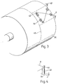
- Figs. 3 and 4 show some details of carrier means on the third roller 36 for the thread deployed from the positioning mechanism, arranged to allow a continuous series of spaced thread loops to be formed on the periphery of the roller at a pitch corresponding to the width of the tea bags.
- For each thread loop there is an arrangement of four projecting pins 42 provided with notches 44 (Fig. 4) or hooks or both near their outer ends, so arranged as to catch a thread that is laid around them by a dispensing wand (Fig. 4 or Fig. 6). It will be noted that the thread is shown disposed entirely to one side of a centre line 48 indicating a radial plane at the middle of the axial length of the roller.
- a similar thread loop pattern can therefore be laid on the other half of the roller periphery, in mirror image to the illustrated thread pattern.
- the webs 2a,2b are double the width of the individual tea bags so as to form two rows of bags side by side, the bags being separated from each other after they have been fully formed. Because the thread for each row does not extend over the centre of the web width, the two thread loop patterns are formed and secured independently of each other.
- Fig. 5 illustrates a first wand mechanism for positioning the thread on the carrier means of the roller 36.
- the mechanism comprises a parallelogram linkage one of the arms of which is formed by a wand 52 in the form of an elongate tube 54 through which the thread is fed over an entry guide roller 56.
- One of the pivots of the arm 60 parallel to the wand has a fixed anchorage 62 arm 60 and a further arm 64 of the linkage have extensions 60a,64a carrying followers which are guided in closed tracks 66,68 of respective rotary cams 70,72.
- the cams 70,72 are rotated in synchronism and their tracks 66,68 are so shaped that the thread exit end of the wand 52 orbits on a path 74 in the form of an approximately triangular loop.
- the thread 8 reaches the surface of the roller and is laid around successive sets of pins 42 in a series of loops which are spaced at intervals around the roller periphery, one such loop being shown in Fig. 3. These loops are temporarily retained by the notches or hooks 44 of the pins.
- a set of four heatable sealing pads 76 are provided in locations which are crossed by the thread 8. As the third roller rotates each loop is brought in turn to the paper web 2b entering the apparatus around the upper roller 32 and the associated sealing pads 76 are then heated to tack the thread to the web.
- the tacked thread loops are immediately released from the carrier means of the third roller 36 and travel onwards with the web 2b.
- the pads 76 are so located that the tacking welds are in zones that are overlaid eventually by the edge seal portions 12 and 14 of the tea bags.
- the pins 42 are preferably displaceably mounted on the roller.
- the pins may be radially displaceable to be lowered flush with the third roller periphery when the loops are transferred; this displacement may be obtained by holding the pins resiliently in their projecting positions or by providing a cam-operated mechanism to draw the pins in.
- the thread may be sprung over the ends of the pins 42 as they are retracted if it is held by hooks or notches 44 such as are shown in Fig. 4. It may be desired, however, to rotate the pins, eg. by a cam mechanism operating on an arm 78 (Fig. 4) of each pin, at the moment of transfer to facilitate the release of the looped thread from the third roller.
- FIG. 6 illustrates a thread feed mechanism for limiting thread tension which comprises a motorised drive device 80 drawing the thread 8 from a bobbin 82 through an entry guide eyelet 84. Downstream of the drive device the thread runs in an open loop 8' depending into the outer end of a suction tube 86. A central barrier 88 in the tube keeps the two lengths of the loop separate and a pervious screen 90 limits the penetration of the loop into the tube. Between the barrier 88 and the screen 90 the presence of the thread loop is detected by a sensing device 92, eg. a light-sensitive device, which is connected to a control circuit (not shown) for the drive device 80.
- a sensing device 92 eg. a light-sensitive device
- the drive 92 is operated to draw more thread from the bobbin. As thread gathers to lengthen the loop 8' it triggers the sensing device 92 and the drive is stopped or slowed.
- the distance of the sensing device from the barrier 90 and the rate at which the drive device 80 draws thread from the bobbin ensure that the thread loop 8' is always maintained at such a length that it will not tighten around the barrier 88.
- the tension load on the thread feed to the third roller 36 is thus limited to the suction force applied to it in the tube 86.
- Fig. 7 illustrates an alternative mechanism for generating the looped path 74 of the tip of the wand 54 required to place the thread around the pins 42 on the third roller 36.
- the wand is held slidably in a longitudinally fixed but pivotable guide 94 so that it can move longitudinally in the guide under the action of a first driven crank 96.
- a second driven crank 98 pivoted to the wand remote from the guide swings the wand tip laterally and by coordination of the movements of the two cranks the required loop-form path is produced for the wand tip.
Landscapes
- Engineering & Computer Science (AREA)
- Mechanical Engineering (AREA)
- Packages (AREA)
- Medical Preparation Storing Or Oral Administration Devices (AREA)
- Containers And Plastic Fillers For Packaging (AREA)
- Preparation Of Compounds By Using Micro-Organisms (AREA)
- Immobilizing And Processing Of Enzymes And Microorganisms (AREA)
- Medicines Containing Material From Animals Or Micro-Organisms (AREA)
- Distillation Of Fermentation Liquor, Processing Of Alcohols, Vinegar And Beer (AREA)
- Separation Using Semi-Permeable Membranes (AREA)
- Filtering Materials (AREA)
- Making Paper Articles (AREA)
Abstract
Description
- This invention relates to the production of packets in which a quantity of infusible material is held in a porous envelope which can be immersed in water to prepare an infusion. It is particularly concerned with a method of and apparatus for producing the packets, and the present patent application is divided from EP 754152 which is concerned with packets of this kind.
- When an infusion is prepared using such a packet a quantity of infused liquid is retained in the packet, usually both by the infusible material and by the material of the packet envelope, and mechanical means have been proposed for extracting at least some of that liquid by applying pressure to the packet. In particular, it has been proposed as a convenient and hygienic solution to provide the packet with draw strings which can be manipulated to contract the packet. Examples of such packets are disclosed in US 3539355, 3237550, 2881910 and 2466281.
- GB 910724 discloses an apparatus in accordance with the preamble of claim 7 and describes the manufacture of tagged tea bags in which a tag is attached to the bag by a thread, which however cannot function as a drawstring. The packet material is formed into a continuous series of open-topped compartments into which doses of tea are placed and then loops of thread are inserted, with ends projecting, after which the tops of the compartments are sealed and the bags are severed from each other with one end of the thread exposed.
- With regard to the drawstring bags referred to above, in US 3539355, 2881910 and 2466281 a draw string or thread passes through holes in the walls of the packet, which is thus liable to leak its contents before use. Moreover, pulling on the draw strings will create high stress concentrations at the edges of the holes, with the risk of tearing and the spillage of a quantity of the infused material into the infusion as the packet is being wrung out over it. Strengthening the walls of the packet is not a solution because of cost and because it is likely to impair the efficiency of infusion.
- In US 3237550 a string loop passes around the packet, the ends of the loop being held captive by a staple punched through an edge of the packet. Pulling the ends apart to shorten the loop contracts the packet. The staple must hold the ends sufficiently loosely to allow them to slide easily when the ends are pulled apart, but not so loosely that it allows the loop to slacken and slip off the other end of the packet, or the ends to slip out of the staple. It will be appreciated that close manufacturing tolerances must be maintained to ensure satisfactory use of such packets and the arrangement is thus ill-suited to economical large scale production. It is also a feature of this form of packet that the wringing action is concentrated along the centre line of the packet and the side edge regions may retain a considerable part of the liquid when the loop is tightened. A somewhat analogous arrangement is shown in US 3539355, in which a stiff paper strip takes the place of the string loop. This similarly does not adapt itself to economical large scale production.
- It is also known from WO91/13580, WO92/06903 and CN 93103319.5 to locate a loop of thread within a packet, an intermediate portion of the loop being anchored in a heat sealed side edge margin of the packet and the ends of the loop projecting out of the opposite side edge margin, in accordance with the preamble of claim 1. The presence of the thread in the edge seals, and in particular in the side edge anchoring the intermediate portion of the loop, weakens the seals however. This effect is intensified by the local stresses generated on the edge seal when tension is applied to the loop ends to wring moisture from the bag consequently rupture of the bag can too easily occur and the infusion material be spilled. Furthermore, these proposals for wringable infusion packets do not disclose any way in which the packets can be reasonably produced in large quantities.
- According to one aspect of the present invention, there is provided a method of producing infusion packets containing doses of infusible material, in which a thread forming a pattern comprising a longitudinally spaced series of loops is enclosed between opposed heat-sealable packet walls of porous material, portions of the thread between said loops projecting from the packets to provide a means for contracting said loops when in use, said walls being secured together to form enclosed packages by heat-sealing the edges of said packets, each packet edge seal having a first region securing an intermediate portion of the associated thread loop, characterized in that in the production of packets, the looped thread is placed against one of a pair of webs of said porous material and the second of said webs is placed against the first web with the thread loops between the webs before the edges of the webs are heat-sealed together along their length and the webs are sealed together transversely at intervals along their length to divide them into a series of sealed compartments each having a thread loop and a dose of said infusible material, the separation of said compartments from the webs providing the packets, said sealing of the webs leaving channels for said portions of the thread between the loops to project from the packets.
- An advantage of such a method of producing the packets is that it can operate in a continuous manner, the thread being laid in said pattern of loops in a continuous length, preferably before being brought together with said one web, and the individual loops being separated from each other after they are secured to said one web. Conveniently the material to be packaged is placed on the other of the webs before it is brought together with said one web and the looped thread thereon.
- A further aspect of the invention provides apparatus for producing packets of infusible material each containing a thread loop and a dose of said material, comprising means for bringing a pair of webs together, means for locating between the webs spaced doses of the infusible material and a series of correspondingly spaced loops of a thread, sealing means for sealing the peripheries of the packets to enclose said doses of infusible material, and means for dividing the joined webs into packets each having a dose of said material and corresponding thread loop, and for separating the ends of each thread loop from the loops of adjoining packets, characterized in that the thread locating means comprise means for forming the thread loops and for placing the spaced loops against one of the webs and attaching them thereto before the webs are brought together.
- The end portions of each loop may be secured to an edge region of the webs, preferably in an easily releasable manner. The intermediate region may be secured to an opposite edge region of the webs and if so this is preferably done simultaneously with the securing of said end portions.
- To form the loops a tubular delivery member may be provided as a thread guide, an outlet end of the member from which the thread is dispensed being displaceable in a circulatory path by drive means acting on the delivery member to form said loops.
- In a preferred arrangement of the apparatus, the loops are formed upon a roller by means of which they are carried on one of said webs to be attached thereto before the webs are brought together.
- To lay the thread in an optimum form of loop may require the speed of delivery of the thread to vary in the course of forming the loop. To limit the tension produced in the thread by the cyclical acceleration, suction means may be provided to maintain a free loop of thread in a feed line to the delivery device, whereby the rate of delivery from said free loop can be varied relative to the rate of feed thereto.
- The invention will be further described by way of example with reference to the accompanying drawings, in which:
- Fig. 1 illustrates one form of infusion packet that can be produced by a method and apparatus according to the invention,
- Fig. 2 is a schematic illustration of apparatus for producing a series of packets of the form shown in Fig. 1,
- Fig. 3 illustrates a means for forming the thread loops,
- Fig. 4 is a detail illustration sharing a feature of the arrangement in Fig. 3,
- Fig. 5 illustrates one form of thread feed mechanism for forming the loops,
- Fig. 6 illustrates a tension control device for the thread feed means, and
- Fig. 7 illustrates an alternative thread feed device for forming the loops.
-
- Fig. 1 illustrates a tea bag T which comprises two
identical layers 2 of conventional heat sealable paper, eg. Dexter 7146 (RTM), heat sealed together around their peripheries with a crimped orflat seal 4. Within the peripheral seal 4 adose 6 of infusible material is held between the two paper layers. A length ofthread 8 is also sandwiched between the layers in a loop pattern, its crossed ends emerging from an upper edge of the tea bag. - A
central portion 8a of the thread is firmly fixed by theheat seal 4 where it is between the layers in a wider,lower edge portion 12 of the seal. The twoends lower edge portion 12 and extend between the layers, diagonally oppositely across the tea bag, and through theupper edge seal 14. Within the upper edge seal the two ends of the thread are held innarrow channels 16 where the paper layers are more lightly sealed together than the remainder of the peripheral seal. The retention of the thread by the heat seal material in these channels can easily be sheared by pulling on the exposed thread ends and the thread is then able to slide in these channels. It is possible alternatively to leave thechannels 16 unsealed if they are sufficiently restricted to avoid any significant leakage of the contents of the bag. - In use, after the tea in the bag has been infused, the tea bag may be removed from the liquid, held by the
free ends channels 16 they are still held within those channels and between the ends thethread 8 is still firmly secured by the wider loweredge seal portion 12. The bag itself is therefore contracted and puckered by the tension in the thread so that the infusible material within it is subjected to a wringing action to extract infusion liquid in the bag. - The top and
bottom sealing margins thread 8 passes are made relatively wide to increase their resistance to tearing or delamination when the thread ends are pulled to apply a wringing force.Reliefs 22 at the ends of thelower edge portion 12 give a relatively wide seal area there to take the force that the thread applies across the seal. The relatively wideupper edge seal 14 also has the advantage of increasing the length of thechannels 16 and so reducing any tendency of particles of the infusible material to escape along these restricted routes when the seal in them is broken. - Tea bags of the illustrated form can be produced in a continuous process as outlined with the apparatus of Fig. 2. This shows a first web 2a of the heat sealable paper carrying spaced
doses 6 of infusible material, which have been deposited by adosing wheel 31 in known manner, and a secondsimilar web 2b joining the first web to enclose the doses between the webs. Thesecond web 2b enters around the upper one of a pair ofheat seal rollers peripheral seals 4 before the individual tea bags are separated. Adjacent the path of the web over theupper roller 32 is athird roller 36 with which is associated athread positioning mechanism 38 for deploying the thread in its looped pattern on the periphery of the third roller. As the laid thread comes adjacent theupper roller 36 it is attached to theweb 2b running over that roller and is so carried on its web to be sandwiched between the twowebs 2a,2b as they pass through theheat seal rollers rollers 35 separate the individual packets and also cut the thread between the packets. - The sealing pattern impressed by the
rollers central portion 8a of the thread is fixed, parallel to the crimped lines. In this manner theportion 8a can be fixed without risk to the integrity of the seal. - Figs. 3 and 4 show some details of carrier means on the
third roller 36 for the thread deployed from the positioning mechanism, arranged to allow a continuous series of spaced thread loops to be formed on the periphery of the roller at a pitch corresponding to the width of the tea bags. For each thread loop there is an arrangement of four projectingpins 42 provided with notches 44 (Fig. 4) or hooks or both near their outer ends, so arranged as to catch a thread that is laid around them by a dispensing wand (Fig. 4 or Fig. 6). It will be noted that the thread is shown disposed entirely to one side of acentre line 48 indicating a radial plane at the middle of the axial length of the roller. A similar thread loop pattern can therefore be laid on the other half of the roller periphery, in mirror image to the illustrated thread pattern. With this arrangement thewebs 2a,2b are double the width of the individual tea bags so as to form two rows of bags side by side, the bags being separated from each other after they have been fully formed. Because the thread for each row does not extend over the centre of the web width, the two thread loop patterns are formed and secured independently of each other. - Fig. 5 illustrates a first wand mechanism for positioning the thread on the carrier means of the
roller 36. The mechanism comprises a parallelogram linkage one of the arms of which is formed by awand 52 in the form of anelongate tube 54 through which the thread is fed over anentry guide roller 56. One of the pivots of thearm 60 parallel to the wand has a fixedanchorage 62arm 60 and afurther arm 64 of the linkage haveextensions closed tracks rotary cams cams tracks wand 52 orbits on apath 74 in the form of an approximately triangular loop. - Because the
third roller 36 is rotating as the wand tip describes its loop-forming orbit, thethread 8 reaches the surface of the roller and is laid around successive sets ofpins 42 in a series of loops which are spaced at intervals around the roller periphery, one such loop being shown in Fig. 3. These loops are temporarily retained by the notches or hooks 44 of the pins. In the portions of the periphery of the third roller associated with each loop a set of fourheatable sealing pads 76 are provided in locations which are crossed by thethread 8. As the third roller rotates each loop is brought in turn to thepaper web 2b entering the apparatus around theupper roller 32 and the associated sealingpads 76 are then heated to tack the thread to the web. The tacked thread loops are immediately released from the carrier means of thethird roller 36 and travel onwards with theweb 2b. Thepads 76 are so located that the tacking welds are in zones that are overlaid eventually by theedge seal portions - To hold the thread loops stably on the
third roller 36 before transfer to theweb 2b and to ensure transfer without snagging, thepins 42 are preferably displaceably mounted on the roller. For example, the pins may be radially displaceable to be lowered flush with the third roller periphery when the loops are transferred; this displacement may be obtained by holding the pins resiliently in their projecting positions or by providing a cam-operated mechanism to draw the pins in. The thread may be sprung over the ends of thepins 42 as they are retracted if it is held by hooks ornotches 44 such as are shown in Fig. 4. It may be desired, however, to rotate the pins, eg. by a cam mechanism operating on an arm 78 (Fig. 4) of each pin, at the moment of transfer to facilitate the release of the looped thread from the third roller. - Whatever way the transfer is effected, it is preferable to ensure that by this stage the thread has been drawn taut into the loop pattern assumed in the finished tea bag. It is particularly desirable to locate as precisely as possible the
ends passages 16 in theupper edge seal 14 in order to keep the width of the passages to a minimum. - Forming the loop patterns with the thread may require significant variations of velocity of the thread as it emerges from the wand. It is desirable to ensure that accelerations imposed on the thread do not lead to excessive tension loads. Fig. 6 illustrates a thread feed mechanism for limiting thread tension which comprises a
motorised drive device 80 drawing thethread 8 from abobbin 82 through anentry guide eyelet 84. Downstream of the drive device the thread runs in an open loop 8' depending into the outer end of asuction tube 86. Acentral barrier 88 in the tube keeps the two lengths of the loop separate and apervious screen 90 limits the penetration of the loop into the tube. Between thebarrier 88 and thescreen 90 the presence of the thread loop is detected by asensing device 92, eg. a light-sensitive device, which is connected to a control circuit (not shown) for thedrive device 80. - If the thread loop 8' is too short to reach the sensing device the
drive 92 is operated to draw more thread from the bobbin. As thread gathers to lengthen the loop 8' it triggers thesensing device 92 and the drive is stopped or slowed. The distance of the sensing device from thebarrier 90 and the rate at which thedrive device 80 draws thread from the bobbin ensure that the thread loop 8' is always maintained at such a length that it will not tighten around thebarrier 88. Apart from any friction in the wand, the tension load on the thread feed to thethird roller 36 is thus limited to the suction force applied to it in thetube 86. - Fig. 7 illustrates an alternative mechanism for generating the looped
path 74 of the tip of thewand 54 required to place the thread around thepins 42 on thethird roller 36. The wand is held slidably in a longitudinally fixed butpivotable guide 94 so that it can move longitudinally in the guide under the action of a first drivencrank 96. A second driven crank 98 pivoted to the wand remote from the guide swings the wand tip laterally and by coordination of the movements of the two cranks the required loop-form path is produced for the wand tip.
Claims (14)
- A method of producing infusion packets containing doses of infusible material, in which a thread (8) forming a pattern comprising a longitudinally spaced series of loops is enclosed between opposed heat-sealable packet walls (2a,2b) of porous material, portions of the thread between said loops projecting from the packets to provide a means for contracting said loops when in use, said walls being secured together to form enclosed packages by heat-sealing the edges of said packets, each packet edge seal having a first region (12) securing an intermediate portion of the associated thread loop,
characterized in that, in the production of packets, the looped thread (8) is placed against one of a pair of webs of said porous material (2b) and the second of said webs (2a) is placed against the first web with the thread loops between the webs before the edges of the webs are heat-sealed together along their length and the webs are sealed together transversely at intervals along their length to divide them into a series of sealed compartments each having a thread loop and a dose (6) of said infusible material, the separation of said compartments from the webs providing the packets, said sealing of the webs leaving channels (16) for said portions of the thread between the loops to project from the packets. - A method according to claim 1 wherein the thread (8) is laid in said pattern of spaced loops and is thereafter transferred and secured to said one web (2b).
- A method according to claim 2 wherein the material (6) to be packaged is placed on the other of the webs (2a) before it is brought together with the one (2b) web and the looped thread thereon.
- A method according to any one of claims 1 to 3 wherein at said passages (16) for the thread ends the thread is detachably secured to the webs by said sealing means.
- A method according to any one of the preceding claims wherein the thread loops of the respective packets are severed from each other simultaneously with said separation of the sealed compartments providing the packets.
- A method according to any one of the preceding claims wherein the looped thread is placed against said one web so as to overlap a side edge of the web to form said projecting thread portions.
- Apparatus for producing packets of infusible material each containing a thread loop and a dose of said material, comprising means for bringing a pair of webs together, means for locating between the webs spaced doses of the infusible material and a series of correspondingly spaced loops of a thread, sealing means (32,34) for sealing the peripheries of the packets to enclose said doses of infusible material, and means (35) for dividing the joined webs into packets each having a dose of said material and corresponding thread loop, and for separating the ends of each thread loop from the loops of adjoining packets, characterised in that the thread locating means comprise means (36,38) for forming the thread loops and for placing the spaced loops against one of the webs and attaching them thereto before the webs are brought together.
- Apparatus according to claim 7 comprising a roller (36) on which said loops are formed and are carried onto one said web (2b) to be attached thereto before the two webs are brought together.
- Apparatus according to claim 8 wherein said means (38) are provided to form the loops on said roller before the thread loops are placed in contact with said one web to be attached thereto.
- Apparatus according to claim 8 or claim 9 wherein said loops are laid onto the roller (36) by a tubular delivery member (54) through which the thread passes, an outlet end of the member being displaced in a circulatory path to form the loops on the roller.
- Apparatus according to any one of claims 8 to 10 wherein said roller (36) is provided with projecting location means (42) around which the loops are held, said location means being displaceable for assisting the transfer of the loops to said other web.
- Apparatus according to any one of claims 8 to 11 wherein the roller is provided with heating means (76) to attach the loops by heat seals to said one web.
- Apparatus according to any one of claims 7 to 12 wherein suction means (86) are provided to maintain a free loop of thread in a feed line of thread for forming the loops to be attached to said one web, whereby to limit the feed tension of the thread.
- Apparatus according to any one of claims 7 to 13 wherein means (38) for forming said thread loops are located between means (31) for dispensing said doses of material and said sealing means (32,34) for sealing the peripheries of the packets.
Applications Claiming Priority (3)
| Application Number | Priority Date | Filing Date | Title |
|---|---|---|---|
| GB9406833A GB9406833D0 (en) | 1994-04-07 | 1994-04-07 | Packets and their manufacture |
| GB9406833 | 1994-04-07 | ||
| EP95913915A EP0754152B1 (en) | 1994-04-07 | 1995-04-04 | Infusion packet |
Related Parent Applications (2)
| Application Number | Title | Priority Date | Filing Date |
|---|---|---|---|
| EP95913915A Division EP0754152B1 (en) | 1994-04-07 | 1995-04-04 | Infusion packet |
| EP95913915.5 Division | 1995-10-19 |
Publications (2)
| Publication Number | Publication Date |
|---|---|
| EP0795476A1 EP0795476A1 (en) | 1997-09-17 |
| EP0795476B1 true EP0795476B1 (en) | 1999-07-28 |
Family
ID=10753112
Family Applications (2)
| Application Number | Title | Priority Date | Filing Date |
|---|---|---|---|
| EP97107482A Expired - Lifetime EP0795476B1 (en) | 1994-04-07 | 1995-04-04 | Method and apparatus for producing infusion packets |
| EP95913915A Expired - Lifetime EP0754152B1 (en) | 1994-04-07 | 1995-04-04 | Infusion packet |
Family Applications After (1)
| Application Number | Title | Priority Date | Filing Date |
|---|---|---|---|
| EP95913915A Expired - Lifetime EP0754152B1 (en) | 1994-04-07 | 1995-04-04 | Infusion packet |
Country Status (15)
| Country | Link |
|---|---|
| US (2) | US5855938A (en) |
| EP (2) | EP0795476B1 (en) |
| JP (1) | JP3747943B2 (en) |
| AT (2) | ATE182541T1 (en) |
| AU (2) | AU698347B2 (en) |
| CA (1) | CA2185696A1 (en) |
| DE (2) | DE69511391T2 (en) |
| ES (2) | ES2134044T3 (en) |
| GB (1) | GB9406833D0 (en) |
| IN (1) | IN187191B (en) |
| NZ (2) | NZ330229A (en) |
| TR (1) | TR28410A (en) |
| TW (1) | TW273537B (en) |
| WO (1) | WO1995027666A2 (en) |
| ZA (1) | ZA952895B (en) |
Families Citing this family (23)
| Publication number | Priority date | Publication date | Assignee | Title |
|---|---|---|---|---|
| GB9422999D0 (en) * | 1994-11-15 | 1995-01-04 | Ag Patents Ltd | Method and apparatus for the manufacture of infusion packages |
| ES2155630T3 (en) * | 1995-11-17 | 2001-05-16 | Unilever Nv | ENVELOPE OF INFUSION AND ITS MANUFACTURE. |
| IT1279697B1 (en) * | 1995-12-07 | 1997-12-16 | Tecnomeccanica Srl | MACHINE FOR PACKAGING ASSEMBLIES FOR INFUSION IN A LIQUID IN WHICH AN INFUSIBLE PRODUCT IS CONTAINED IN A FILTER BAG IN |
| EP0806352B1 (en) * | 1996-05-07 | 2001-11-07 | Teepack Spezialmaschinen Gmbh & Co. Kg | Twin-compartment infusion bag, especially for tea, and process for its manufactue |
| WO1998002365A1 (en) * | 1996-07-11 | 1998-01-22 | Unilever Plc | Infusion package and their manufacture |
| IT1286767B1 (en) * | 1996-11-15 | 1998-07-17 | Luxteco International S A Soci | PACKAGING EQUIPMENT |
| WO1999003734A1 (en) * | 1997-07-18 | 1999-01-28 | Thaumaturge Pty. Limited | Squeezable beverage bags |
| GB9722490D0 (en) * | 1997-10-25 | 1997-12-24 | Cambridge Consultants | Improvements in and relating to tags and their attachment to products |
| AU5819200A (en) * | 1999-07-14 | 2001-02-05 | Unilever Plc | Apparatus for attaching a tag and a thread to a web of filter material |
| AU3269201A (en) * | 1999-11-12 | 2001-06-06 | Krumpet International, Llc | Infusion bag squeezing assembly |
| AU2003211855A1 (en) * | 2002-02-07 | 2003-09-02 | Teangle A/S | A tea bag |
| USD526892S1 (en) | 2004-04-13 | 2006-08-22 | Innovative Beverage Concepts, Inc. | Tea sachet packaging |
| US7523595B2 (en) * | 2005-10-12 | 2009-04-28 | Haussier & Sauter Kg | Method for attaching a draw string to an infusion bag automatically |
| US20070087083A1 (en) * | 2005-10-18 | 2007-04-19 | Riley William T | Tea bag cozy |
| FR2897047B1 (en) * | 2006-02-07 | 2008-05-02 | Cie Mediterraneenne Des Cafes | PACKAGING FOR INFUSER SUBSTANCE |
| JP5397381B2 (en) * | 2009-11-20 | 2014-01-22 | 大紀商事株式会社 | Extraction bag sheet manufacturing method and manufacturing machine |
| WO2011158293A1 (en) * | 2010-06-17 | 2011-12-22 | 不双産業株式会社 | Extraction bag and packaging material sheet |
| RU2446085C1 (en) | 2010-08-20 | 2012-03-27 | Елена Аркадьевна Меринова | Disposable sieve for tea brewing with spinning system |
| RU2011143577A (en) * | 2011-10-28 | 2013-05-10 | Елена Аркадьевна Меринова | DISPOSABLE WELDING SYSTEMS WITH SPIN SYSTEM |
| RU2011149134A (en) * | 2011-12-02 | 2015-03-27 | Елена Аркадьевна Меринова | METHOD FOR MANUFACTURING A DISPOSABLE BREWING SCREEN WITH EXTRACTION SYSTEM |
| EP2626318B1 (en) * | 2012-02-10 | 2015-01-21 | Teepack Spezialmaschinen Gmbh & Co. Kg | Infusion bag |
| ITBO20120208A1 (en) | 2012-04-17 | 2013-10-18 | Ima Ind Srl | SOVRA ENVELOPE ENVELOPE FOR BAGS - INFUSION AND WELDER DEVICE PRODUCT FILTER TO OBTAIN THE LARGE ENVELOPE ENVELOPE |
| GB2566737A (en) * | 2017-09-25 | 2019-03-27 | Milne Downey Donald | Infusion device |
Family Cites Families (28)
| Publication number | Priority date | Publication date | Assignee | Title |
|---|---|---|---|---|
| US2335159A (en) * | 1941-09-30 | 1943-11-23 | Ivers Lee Co | Adhesively sealed package |
| US2350930A (en) * | 1942-01-01 | 1944-06-06 | Ivers Lee Co | Machine for making and filling packages |
| US2334256A (en) * | 1942-03-25 | 1943-11-16 | Pneumatic Scale Corp | Method of and apparatus for making bags |
| US2406018A (en) * | 1942-10-14 | 1946-08-20 | Nat Urn Bag Co Inc | Method of manufacturing infusion packages |
| US2466281A (en) * | 1947-09-23 | 1949-04-05 | William R Shaw | Tea bag |
| FR1169388A (en) * | 1957-03-12 | 1958-12-26 | Pneumatic Scale Corp | Infusion bag |
| US2881910A (en) * | 1958-04-17 | 1959-04-14 | Clarence W Jones | Tea bag |
| US3191355A (en) * | 1960-01-16 | 1965-06-29 | Morpurgo Fulvio | Tea bags and apparatus for use in their manufacture |
| US3143834A (en) * | 1961-05-24 | 1964-08-11 | Nat Tea Packing Company Inc | Compressible infusion package |
| US3237550A (en) * | 1963-10-18 | 1966-03-01 | Joseph A Christopher | Extraction package for infusion materials |
| US3316686A (en) * | 1964-03-16 | 1967-05-02 | Welin-Berger Guy John Olof | Method of manufacturing a package |
| US3415656A (en) * | 1965-09-09 | 1968-12-10 | Philip L. Lundgren | Compressible infusion bag |
| US3539355A (en) * | 1967-06-28 | 1970-11-10 | Sam Kasakoff | Coffee filter bag |
| US3597222A (en) * | 1968-03-22 | 1971-08-03 | Thaddeus John Kalemba | Infusion packet |
| IT1207875B (en) * | 1979-03-06 | 1989-06-01 | Ima Spa | EQUIPMENT FOR THE APPLICATION OF A SUSPENSION WIRE TO BAGS FILTER FOR INFUSION PRODUCTS |
| CH661905A5 (en) * | 1983-09-02 | 1987-08-31 | Tourpac Productions Ag | Process and apparatus for connecting a bag to a label |
| US4551336A (en) * | 1983-12-22 | 1985-11-05 | Chen Ying Cheng | Infusion bag |
| IT1207629B (en) * | 1987-03-09 | 1989-05-25 | Cestind Centro Studi Ind | SWIVEL WHEEL EQUIPMENT WITH GRIPPING MACHINES TO APPLY LABELS AND WIRE TO A FILLED TUBE ACCORDING TO BAGS-FILTER DISPOSABLE IN SERIES IN CONTINUOUS PACKAGING MACHINES OF SAID BAGS-FILTER |
| US5358724A (en) * | 1990-03-14 | 1994-10-25 | Raffaele Peter R | Double chamber infusion bag and method of manufacture |
| TR26456A (en) * | 1990-03-21 | 1995-03-15 | Unilever Nv | METHODS AND DEVICES FOR PRODUCTION OF TWIN-SECTION PACKS AND TWIN-SECTION PACKS. |
| ATE116252T1 (en) * | 1990-10-10 | 1995-01-15 | Tidy Tea Ltd | INFUSION BAGS. |
| GB9026123D0 (en) * | 1990-11-30 | 1991-01-16 | Unilever Plc | Tagged articles and method and apparatus for their production |
| GB9103156D0 (en) * | 1991-02-14 | 1991-04-03 | Ag Patents Ltd | Manufacturing infusion packages |
| US5674545A (en) * | 1992-03-27 | 1997-10-07 | Tidy Tea Limited | Compressible packages for infusible substances |
| GB9219657D0 (en) * | 1992-09-17 | 1992-10-28 | Unilever Plc | Tagged articles |
| TW264443B (en) * | 1992-10-02 | 1995-12-01 | Unilever Nv | |
| PL177401B1 (en) * | 1993-10-12 | 1999-11-30 | Unilever Nv | Infusion packs and method of making them |
| GB9422999D0 (en) * | 1994-11-15 | 1995-01-04 | Ag Patents Ltd | Method and apparatus for the manufacture of infusion packages |
-
1994
- 1994-04-07 GB GB9406833A patent/GB9406833D0/en active Pending
-
1995
- 1995-03-30 TW TW084103058A patent/TW273537B/zh active
- 1995-04-04 AT AT97107482T patent/ATE182541T1/en not_active IP Right Cessation
- 1995-04-04 ES ES97107482T patent/ES2134044T3/en not_active Expired - Lifetime
- 1995-04-04 NZ NZ330229A patent/NZ330229A/en unknown
- 1995-04-04 DE DE69511391T patent/DE69511391T2/en not_active Expired - Fee Related
- 1995-04-04 ES ES95913915T patent/ES2136283T3/en not_active Expired - Lifetime
- 1995-04-04 AT AT95913915T patent/ATE183165T1/en not_active IP Right Cessation
- 1995-04-04 WO PCT/GB1995/000775 patent/WO1995027666A2/en not_active Ceased
- 1995-04-04 EP EP97107482A patent/EP0795476B1/en not_active Expired - Lifetime
- 1995-04-04 NZ NZ283155A patent/NZ283155A/en unknown
- 1995-04-04 CA CA002185696A patent/CA2185696A1/en not_active Abandoned
- 1995-04-04 AU AU21126/95A patent/AU698347B2/en not_active Ceased
- 1995-04-04 DE DE69511104T patent/DE69511104T2/en not_active Expired - Fee Related
- 1995-04-04 JP JP52615495A patent/JP3747943B2/en not_active Expired - Fee Related
- 1995-04-04 EP EP95913915A patent/EP0754152B1/en not_active Expired - Lifetime
- 1995-04-07 IN IN170BO1995 patent/IN187191B/en unknown
- 1995-04-07 ZA ZA952895A patent/ZA952895B/en unknown
- 1995-04-07 TR TR00380/95A patent/TR28410A/en unknown
-
1996
- 1996-10-01 US US08/724,339 patent/US5855938A/en not_active Expired - Fee Related
-
1997
- 1997-07-31 AU AU32425/97A patent/AU686984B3/en not_active Ceased
-
1998
- 1998-04-17 US US09/062,352 patent/US5878550A/en not_active Expired - Fee Related
Also Published As
| Publication number | Publication date |
|---|---|
| NZ330229A (en) | 2000-01-28 |
| JP3747943B2 (en) | 2006-02-22 |
| NZ283155A (en) | 1998-09-24 |
| TR28410A (en) | 1996-06-19 |
| US5855938A (en) | 1999-01-05 |
| ZA952895B (en) | 1996-10-07 |
| ES2136283T3 (en) | 1999-11-16 |
| DE69511391T2 (en) | 1999-12-30 |
| ES2134044T3 (en) | 1999-09-16 |
| EP0795476A1 (en) | 1997-09-17 |
| WO1995027666A3 (en) | 1995-12-07 |
| EP0754152B1 (en) | 1999-08-11 |
| WO1995027666A2 (en) | 1995-10-19 |
| AU698347B2 (en) | 1998-10-29 |
| IN187191B (en) | 2002-02-23 |
| US5878550A (en) | 1999-03-09 |
| TW273537B (en) | 1996-04-01 |
| AU3242597A (en) | 1997-11-06 |
| AU686984B3 (en) | 1998-02-12 |
| ATE183165T1 (en) | 1999-08-15 |
| DE69511391D1 (en) | 1999-09-16 |
| DE69511104D1 (en) | 1999-09-02 |
| CA2185696A1 (en) | 1995-10-19 |
| ATE182541T1 (en) | 1999-08-15 |
| DE69511104T2 (en) | 1999-11-18 |
| JPH09511475A (en) | 1997-11-18 |
| EP0754152A1 (en) | 1997-01-22 |
| GB9406833D0 (en) | 1994-06-01 |
| AU2112695A (en) | 1995-10-30 |
Similar Documents
| Publication | Publication Date | Title |
|---|---|---|
| US5855938A (en) | Infusion packet | |
| PL177401B1 (en) | Infusion packs and method of making them | |
| PL171052B1 (en) | Method of and apparatus for making infusion bags with labels attached thereto | |
| US5527419A (en) | Apparatus for the production of tagged articles | |
| US5412924A (en) | Method of making reclosable plastic bags on a form, fill and seal machine | |
| US5399224A (en) | Method and apparatus for producing tagged articles | |
| JPH0659883B2 (en) | Method and apparatus for packaging rectangular compressible articles | |
| EP0790927B1 (en) | Method and apparatus for the manufacture of infusion packages | |
| PL184809B1 (en) | Method of and apparatus for making labelled packages and labelled package obtained thereby | |
| AU715300B2 (en) | Infusion package and their manufacture | |
| AU708800B2 (en) | Method and apparatus for the manufacture of packets | |
| CA2237933C (en) | Infusion packet and its manufacture | |
| EP0691915A1 (en) | Improved tabs and manufacture thereof | |
| JP2507402B2 (en) | Tea bag and manufacturing method thereof | |
| WO1997036787A1 (en) | Infusion packages and methods for their manufacture | |
| GB2283223A (en) | Tagged infusion packages |
Legal Events
| Date | Code | Title | Description |
|---|---|---|---|
| PUAI | Public reference made under article 153(3) epc to a published international application that has entered the european phase |
Free format text: ORIGINAL CODE: 0009012 |
|
| 17P | Request for examination filed |
Effective date: 19970526 |
|
| AC | Divisional application: reference to earlier application |
Ref document number: 754152 Country of ref document: EP |
|
| AK | Designated contracting states |
Kind code of ref document: A1 Designated state(s): AT BE CH DE DK ES FR GB GR IE IT LI NL PT SE |
|
| 17Q | First examination report despatched |
Effective date: 19980218 |
|
| GRAG | Despatch of communication of intention to grant |
Free format text: ORIGINAL CODE: EPIDOS AGRA |
|
| GRAG | Despatch of communication of intention to grant |
Free format text: ORIGINAL CODE: EPIDOS AGRA |
|
| GRAH | Despatch of communication of intention to grant a patent |
Free format text: ORIGINAL CODE: EPIDOS IGRA |
|
| GRAH | Despatch of communication of intention to grant a patent |
Free format text: ORIGINAL CODE: EPIDOS IGRA |
|
| GRAA | (expected) grant |
Free format text: ORIGINAL CODE: 0009210 |
|
| AC | Divisional application: reference to earlier application |
Ref document number: 754152 Country of ref document: EP |
|
| AK | Designated contracting states |
Kind code of ref document: B1 Designated state(s): AT BE CH DE DK ES FR GB GR IE IT LI NL PT SE |
|
| PG25 | Lapsed in a contracting state [announced via postgrant information from national office to epo] |
Ref country code: NL Free format text: LAPSE BECAUSE OF FAILURE TO SUBMIT A TRANSLATION OF THE DESCRIPTION OR TO PAY THE FEE WITHIN THE PRESCRIBED TIME-LIMIT Effective date: 19990728 Ref country code: LI Free format text: LAPSE BECAUSE OF FAILURE TO SUBMIT A TRANSLATION OF THE DESCRIPTION OR TO PAY THE FEE WITHIN THE PRESCRIBED TIME-LIMIT Effective date: 19990728 Ref country code: GR Free format text: LAPSE BECAUSE OF NON-PAYMENT OF DUE FEES Effective date: 19990728 Ref country code: CH Free format text: LAPSE BECAUSE OF FAILURE TO SUBMIT A TRANSLATION OF THE DESCRIPTION OR TO PAY THE FEE WITHIN THE PRESCRIBED TIME-LIMIT Effective date: 19990728 Ref country code: AT Free format text: LAPSE BECAUSE OF FAILURE TO SUBMIT A TRANSLATION OF THE DESCRIPTION OR TO PAY THE FEE WITHIN THE PRESCRIBED TIME-LIMIT Effective date: 19990728 |
|
| REF | Corresponds to: |
Ref document number: 182541 Country of ref document: AT Date of ref document: 19990815 Kind code of ref document: T |
|
| REG | Reference to a national code |
Ref country code: CH Ref legal event code: EP |
|
| REF | Corresponds to: |
Ref document number: 69511104 Country of ref document: DE Date of ref document: 19990902 |
|
| REG | Reference to a national code |
Ref country code: ES Ref legal event code: FG2A Ref document number: 2134044 Country of ref document: ES Kind code of ref document: T3 |
|
| ET | Fr: translation filed | ||
| ITF | It: translation for a ep patent filed | ||
| REG | Reference to a national code |
Ref country code: IE Ref legal event code: FG4D |
|
| PG25 | Lapsed in a contracting state [announced via postgrant information from national office to epo] |
Ref country code: PT Free format text: LAPSE BECAUSE OF FAILURE TO SUBMIT A TRANSLATION OF THE DESCRIPTION OR TO PAY THE FEE WITHIN THE PRESCRIBED TIME-LIMIT Effective date: 19991028 Ref country code: DK Free format text: LAPSE BECAUSE OF FAILURE TO SUBMIT A TRANSLATION OF THE DESCRIPTION OR TO PAY THE FEE WITHIN THE PRESCRIBED TIME-LIMIT Effective date: 19991028 |
|
| NLV1 | Nl: lapsed or annulled due to failure to fulfill the requirements of art. 29p and 29m of the patents act | ||
| REG | Reference to a national code |
Ref country code: CH Ref legal event code: PL |
|
| PLBE | No opposition filed within time limit |
Free format text: ORIGINAL CODE: 0009261 |
|
| STAA | Information on the status of an ep patent application or granted ep patent |
Free format text: STATUS: NO OPPOSITION FILED WITHIN TIME LIMIT |
|
| 26N | No opposition filed | ||
| REG | Reference to a national code |
Ref country code: GB Ref legal event code: IF02 |
|
| PGFP | Annual fee paid to national office [announced via postgrant information from national office to epo] |
Ref country code: IE Payment date: 20070426 Year of fee payment: 13 Ref country code: ES Payment date: 20070426 Year of fee payment: 13 |
|
| PGFP | Annual fee paid to national office [announced via postgrant information from national office to epo] |
Ref country code: SE Payment date: 20070427 Year of fee payment: 13 |
|
| PGFP | Annual fee paid to national office [announced via postgrant information from national office to epo] |
Ref country code: BE Payment date: 20070515 Year of fee payment: 13 |
|
| PGFP | Annual fee paid to national office [announced via postgrant information from national office to epo] |
Ref country code: DE Payment date: 20070531 Year of fee payment: 13 |
|
| PGFP | Annual fee paid to national office [announced via postgrant information from national office to epo] |
Ref country code: GB Payment date: 20070425 Year of fee payment: 13 |
|
| PGFP | Annual fee paid to national office [announced via postgrant information from national office to epo] |
Ref country code: IT Payment date: 20070522 Year of fee payment: 13 |
|
| PGFP | Annual fee paid to national office [announced via postgrant information from national office to epo] |
Ref country code: FR Payment date: 20070417 Year of fee payment: 13 |
|
| BERE | Be: lapsed |
Owner name: *UNILEVER N.V. Effective date: 20080430 |
|
| EUG | Se: european patent has lapsed | ||
| GBPC | Gb: european patent ceased through non-payment of renewal fee |
Effective date: 20080404 |
|
| REG | Reference to a national code |
Ref country code: IE Ref legal event code: MM4A |
|
| PG25 | Lapsed in a contracting state [announced via postgrant information from national office to epo] |
Ref country code: DE Free format text: LAPSE BECAUSE OF NON-PAYMENT OF DUE FEES Effective date: 20081101 |
|
| REG | Reference to a national code |
Ref country code: FR Ref legal event code: ST Effective date: 20081231 |
|
| PG25 | Lapsed in a contracting state [announced via postgrant information from national office to epo] |
Ref country code: BE Free format text: LAPSE BECAUSE OF NON-PAYMENT OF DUE FEES Effective date: 20080430 |
|
| PG25 | Lapsed in a contracting state [announced via postgrant information from national office to epo] |
Ref country code: IE Free format text: LAPSE BECAUSE OF NON-PAYMENT OF DUE FEES Effective date: 20080404 Ref country code: FR Free format text: LAPSE BECAUSE OF NON-PAYMENT OF DUE FEES Effective date: 20080430 |
|
| REG | Reference to a national code |
Ref country code: ES Ref legal event code: FD2A Effective date: 20080405 |
|
| PG25 | Lapsed in a contracting state [announced via postgrant information from national office to epo] |
Ref country code: GB Free format text: LAPSE BECAUSE OF NON-PAYMENT OF DUE FEES Effective date: 20080404 |
|
| PG25 | Lapsed in a contracting state [announced via postgrant information from national office to epo] |
Ref country code: ES Free format text: LAPSE BECAUSE OF NON-PAYMENT OF DUE FEES Effective date: 20080405 |
|
| PG25 | Lapsed in a contracting state [announced via postgrant information from national office to epo] |
Ref country code: IT Free format text: LAPSE BECAUSE OF NON-PAYMENT OF DUE FEES Effective date: 20080404 |
|
| PG25 | Lapsed in a contracting state [announced via postgrant information from national office to epo] |
Ref country code: SE Free format text: LAPSE BECAUSE OF NON-PAYMENT OF DUE FEES Effective date: 20080405 |