EP0795176B1 - Data cartridge with composite drive belt - Google Patents
Data cartridge with composite drive belt Download PDFInfo
- Publication number
- EP0795176B1 EP0795176B1 EP95938283A EP95938283A EP0795176B1 EP 0795176 B1 EP0795176 B1 EP 0795176B1 EP 95938283 A EP95938283 A EP 95938283A EP 95938283 A EP95938283 A EP 95938283A EP 0795176 B1 EP0795176 B1 EP 0795176B1
- Authority
- EP
- European Patent Office
- Prior art keywords
- stiffness material
- drive belt
- cartridge
- belt
- tape
- Prior art date
- Legal status (The legal status is an assumption and is not a legal conclusion. Google has not performed a legal analysis and makes no representation as to the accuracy of the status listed.)
- Expired - Lifetime
Links
- 239000002131 composite material Substances 0.000 title description 3
- 239000000463 material Substances 0.000 claims description 62
- 229920000642 polymer Polymers 0.000 claims description 7
- 238000013016 damping Methods 0.000 claims description 6
- 230000009477 glass transition Effects 0.000 claims description 6
- 229920002635 polyurethane Polymers 0.000 claims description 4
- 239000004814 polyurethane Substances 0.000 claims description 4
- 150000003673 urethanes Chemical class 0.000 claims description 4
- 229920000728 polyester Polymers 0.000 claims description 3
- 239000010410 layer Substances 0.000 description 27
- -1 poly(vinyl acetate) Polymers 0.000 description 9
- 238000000034 method Methods 0.000 description 8
- 239000004743 Polypropylene Substances 0.000 description 7
- 229920001155 polypropylene Polymers 0.000 description 7
- 230000008569 process Effects 0.000 description 5
- 238000012360 testing method Methods 0.000 description 4
- 230000035882 stress Effects 0.000 description 3
- 244000043261 Hevea brasiliensis Species 0.000 description 2
- 230000008859 change Effects 0.000 description 2
- 230000000052 comparative effect Effects 0.000 description 2
- 229920003052 natural elastomer Polymers 0.000 description 2
- 229920001194 natural rubber Polymers 0.000 description 2
- 230000007935 neutral effect Effects 0.000 description 2
- 229920000570 polyether Polymers 0.000 description 2
- 229920001296 polysiloxane Polymers 0.000 description 2
- 238000004611 spectroscopical analysis Methods 0.000 description 2
- 229920003048 styrene butadiene rubber Polymers 0.000 description 2
- 238000012935 Averaging Methods 0.000 description 1
- 239000004709 Chlorinated polyethylene Substances 0.000 description 1
- 229920001634 Copolyester Polymers 0.000 description 1
- 229920000459 Nitrile rubber Polymers 0.000 description 1
- 239000005062 Polybutadiene Substances 0.000 description 1
- 239000004721 Polyphenylene oxide Substances 0.000 description 1
- 239000002174 Styrene-butadiene Substances 0.000 description 1
- 230000001133 acceleration Effects 0.000 description 1
- 229920006243 acrylic copolymer Polymers 0.000 description 1
- 229920006397 acrylic thermoplastic Polymers 0.000 description 1
- 230000032683 aging Effects 0.000 description 1
- 229920001400 block copolymer Polymers 0.000 description 1
- NTXGQCSETZTARF-UHFFFAOYSA-N buta-1,3-diene;prop-2-enenitrile Chemical compound C=CC=C.C=CC#N NTXGQCSETZTARF-UHFFFAOYSA-N 0.000 description 1
- MTAZNLWOLGHBHU-UHFFFAOYSA-N butadiene-styrene rubber Chemical compound C=CC=C.C=CC1=CC=CC=C1 MTAZNLWOLGHBHU-UHFFFAOYSA-N 0.000 description 1
- 238000000576 coating method Methods 0.000 description 1
- 238000011109 contamination Methods 0.000 description 1
- 229920001577 copolymer Polymers 0.000 description 1
- 238000003851 corona treatment Methods 0.000 description 1
- 150000002170 ethers Chemical class 0.000 description 1
- 238000007765 extrusion coating Methods 0.000 description 1
- 229920002681 hypalon Polymers 0.000 description 1
- 238000003780 insertion Methods 0.000 description 1
- 230000037431 insertion Effects 0.000 description 1
- 238000010030 laminating Methods 0.000 description 1
- 238000012886 linear function Methods 0.000 description 1
- 238000004519 manufacturing process Methods 0.000 description 1
- 238000005259 measurement Methods 0.000 description 1
- 230000007246 mechanism Effects 0.000 description 1
- 229920001084 poly(chloroprene) Polymers 0.000 description 1
- 229920002755 poly(epichlorohydrin) Polymers 0.000 description 1
- 229920003229 poly(methyl methacrylate) Polymers 0.000 description 1
- 229920000058 polyacrylate Polymers 0.000 description 1
- 229920002857 polybutadiene Polymers 0.000 description 1
- 229920001195 polyisoprene Polymers 0.000 description 1
- 229920003246 polypentenamer Polymers 0.000 description 1
- 229920001451 polypropylene glycol Polymers 0.000 description 1
- 229920002689 polyvinyl acetate Polymers 0.000 description 1
- 239000011118 polyvinyl acetate Substances 0.000 description 1
- 230000002028 premature Effects 0.000 description 1
- 238000005096 rolling process Methods 0.000 description 1
- 239000002356 single layer Substances 0.000 description 1
- 239000011115 styrene butadiene Substances 0.000 description 1
- 229920001897 terpolymer Polymers 0.000 description 1
- ISXSCDLOGDJUNJ-UHFFFAOYSA-N tert-butyl prop-2-enoate Chemical compound CC(C)(C)OC(=O)C=C ISXSCDLOGDJUNJ-UHFFFAOYSA-N 0.000 description 1
Images
Classifications
-
- G—PHYSICS
- G11—INFORMATION STORAGE
- G11B—INFORMATION STORAGE BASED ON RELATIVE MOVEMENT BETWEEN RECORD CARRIER AND TRANSDUCER
- G11B23/00—Record carriers not specific to the method of recording or reproducing; Accessories, e.g. containers, specially adapted for co-operation with the recording or reproducing apparatus ; Intermediate mediums; Apparatus or processes specially adapted for their manufacture
- G11B23/02—Containers; Storing means both adapted to cooperate with the recording or reproducing means
- G11B23/04—Magazines; Cassettes for webs or filaments
- G11B23/08—Magazines; Cassettes for webs or filaments for housing webs or filaments having two distinct ends
- G11B23/087—Magazines; Cassettes for webs or filaments for housing webs or filaments having two distinct ends using two different reels or cores
-
- G—PHYSICS
- G11—INFORMATION STORAGE
- G11B—INFORMATION STORAGE BASED ON RELATIVE MOVEMENT BETWEEN RECORD CARRIER AND TRANSDUCER
- G11B23/00—Record carriers not specific to the method of recording or reproducing; Accessories, e.g. containers, specially adapted for co-operation with the recording or reproducing apparatus ; Intermediate mediums; Apparatus or processes specially adapted for their manufacture
- G11B23/02—Containers; Storing means both adapted to cooperate with the recording or reproducing means
- G11B23/04—Magazines; Cassettes for webs or filaments
- G11B23/08—Magazines; Cassettes for webs or filaments for housing webs or filaments having two distinct ends
- G11B23/087—Magazines; Cassettes for webs or filaments for housing webs or filaments having two distinct ends using two different reels or cores
- G11B23/08707—Details
- G11B23/08778—Driving features, e.g. belt
Definitions
- the present invention concerns a tape cartridge in which a flexible, elastic drive belt contacts the tape which is wound on tape spools and movement of the belt causes movement of the tape between the spools.
- Tension in the tape is created by a difference in belt tension at each tape pack periphery caused by the controlled drag in the corner rollers. This tension difference causes the tape to wind from one spool to another as well as creating the desired value of tension at the read/write head. A minimum tape tension is necessary for reliable reading and recording of information. However, if the tape tension is too high undue wear occurs at the tape/head interface.
- US-A-5,131,891 discloses a two layer drive belt adapted for use in a belt-driven data cartridge which includes tape pack, a drive roller, and the drive belt wound around the tape pack and the roller.
- This known drive belt has a k-factor in the range from 0.01 to 0.25 N -1 and comprises a layer of a high stiffness material and a low stiffness material.
- the present invention provides a belt driven magnetic tape cartridge with a belt which reduces end to end variation in tape tension, i.e. bow-tie, without an undue increase in dynamic tape tension. This is achieved by moving the neutral axis of stress in the belt toward the tape pack as the belt is contacted with the tape pack in an arc.
- this invention is a thin, flexible, continuous belt adapted for use in a belt-driven data cartridge which includes a tape pack, a drive roller, and the belt wound around the tape pack and the roller.
- the belt has a k-factor in the range from 0.01 to 0.25 N -1 and comprises a layer of a high stiffness material and a layer of a low stiffness material, wherein the layer of the high stiffness material is adjacent to the tape pack.
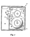
- Figure 1 is a schematic representation of a belt-driven data cartridge.
- a cartridge 10 is shown in a tape deck 28 .
- Cartridge 10 has a pair of hubs 12 and 14 on which is wound a length of magnetic recording tape 16 .
- a drive belt 18 is entrained or wound around a belt drive roller 20 , a pair of belt guide rollers 22 and 24 , and one or two tape packs 17 formed by the portion of tape 16 wound around hubs 12 and 14 .
- drive puck 26 of tape deck 28 contacts belt drive roller 20
- the magnetic recording head 30 of deck 28 contacts tape 16 .
- the belt-contacting portion 32 of belt drive roller 20 is recessed to permit tape 16 to pass without touching roller 20 .
- Stiffness of belt material may be defined in various ways including compliance, which is also known as k-factor.
- k-factor is measured only after the belt has been stretched to the length it would be in the tape cartridge. It is important to perform this step preliminary to testing for two reasons.
- the k-factor is not necessarily a linear function of strain and the belt material may have a different k-factor at its working length and tension than in its original unstretched state.
- the material may have a different k-factor the first time it is stretched than is obtained on subsequent stretching and testing. After the belt is stretched to its working tension or length, the belt is stretched an additional incremental amount and the incremental increase in tension is measured.
- the composite belt of this invention has a k-factor in the range of 0.01 to 0.25 N -1 , preferably 0.01 to 0.1 N -1 .
- the belt working thickness is in the range of 0.05 to 0.127 mm with a working width of about 2-6 mm.
- Working thickness and width refer to the thickness and width when the belt is inserted in a tape cartridge.
- the ratio of the thickness of the high stiffness material to the thickness of the low stiffness material is preferably less than 1:1, more preferably less than 1:2, and most preferably less than 1:3.
- the layer of the high stiffness material has a minimum thickness of about 1.3 ⁇ m, preferably at least 1.5 ⁇ m, more preferably at least 5 ⁇ m.
- the high and low stiffness materials may be defined in terms of the k-factor of a single layer belt having only that material and having a cross section of about 0.19 mm 2 .
- Such a belt made of the high stiffness material alone would preferably have a k-factor of no more than about 0.02 N -1 .
- a similar belt made of a low stiffness material alone would preferably have a k-factor of no less than 0.02 N -1 .
- the modulus of elasticity of the high stiffness material divided by the modulus of elasticity of the low stiffness material is greater than 1, preferably greater than 1.2, more preferably in the range of 1.4-10, and most preferably in the range from 1.5 to 5.
- the neutral axis of stress as the belt contacts the tape pack in an arc be located as close as possible to the interface of the layer of the high stiffness material and the layer of the low stiffness material.
- the material for both layers of the belt may be polymers with elastic characteristics.
- Non-limiting examples of such materials include polyurethanes, copolyester ethers, styrene-diene block copolymers, polyethers, polyacrylates, fluorocarbons, fluorosilicones, fluoroalkoxyphosphazenes, silicones, ethylene-acrylic copolymers, butadiene-acrylonitrile copolymers, natural rubber, styrene butadiene copolymers, polyisoprene, polybutadiene, polychloroprene, isobutylene-propylene-diene terpolymers, polyepichlorohydrin, chlorosulfonated polyethylene, chlorinated polyethylene, polypropylene oxide, and polypentenamers.
- the polyurethanes such as polyether urethanes and polyester urethanes, are preferred, and polyester urethanes are particularly preferred.
- the low stiffness materials are polymers having glass transition temperatures (T g ) of less than -25°C as indicated by the tan delta peak at 1 Hz by Dynamic Mechanical Spectroscopy (DMS).
- T g glass transition temperatures
- the high stiffness materials are preferably polymers having Tg as indicated by the tan delta peak at 1 Hz by DMS in the range of -25 to 50°C, preferably 0 to 50°C.
- a damping material may optionally be used between the low stiffness layer and the high stiffness layer.
- Suitable damping materials preferably have T g between 0 and 50°C at frequency of 0 to 500 Hz.
- Some damping materials include asphaltics, polyurethanes, poly(vinyl acetate) and copolymers thereof, acrylics, natural rubber, styrenebutadiene, and silicones.
- the thickness of the damping layer is preferably from 12 to 100 ⁇ m, more preferably 12 to 50 ⁇ m. Coatings may also be applied to the belt as is known in the art to provide desired antistatic and durability characteristics.
- the composite belt may be manufactured by laminating, by coextruding the high stiffness material and the low stiffness material, or by extrusion coating. A concentric ring is punched out of a sheet of the laminated or coextruded material. This concentric ring is then stretched for insertion into the data cartridge.
- the belts of this invention are manufactured according to the following process:
- Belts were made according to the above procedure. These belts were tested for k-factor according to the method described above. The belts were inserted into cartridges and tape tension variation from the beginning to the end of the tape (bow-tie) and dynamic tape tension were measured. Bowtie is determined by subtracting tape tension measurements at the end of tape (EOT) from those made at the beginning of the tape (BOT). When tape tension is measured, data over one inch spans is used to determine "local" averages, maximums, and minimums. Tape tension at EOT and BOT is determined by averaging the local averages computed over the first (BOT) or last (EOT) 36 inches (91 cm).
- each sample belt had a stretched width of 2.54 mm.
- Layer 1 is the layer closest to the tape pack and Layer 2 is further away from the tape pack.
- Samples 2-6 Layer 1 is stiffer than Layer 2.
- Comparative Sample 1 has only one layer. While Comparative Sample 7 is a two layer belt inserted backwards so that the high stiffness layer is further from the tape pack and the low stiffness layer is closer to the tape pack. The results shown in the Table indicate that the belts of this invention have better bow-tie, i.e. lower end to end variation in tape tension than do non-inventive belts.
Landscapes
- Compositions Of Macromolecular Compounds (AREA)
- Laminated Bodies (AREA)
- Magnetic Record Carriers (AREA)
- Mechanical Pencils And Projecting And Retracting Systems Therefor, And Multi-System Writing Instruments (AREA)
- Inks, Pencil-Leads, Or Crayons (AREA)
- Input Circuits Of Receivers And Coupling Of Receivers And Audio Equipment (AREA)
Description
- The present invention concerns a tape cartridge in which a flexible, elastic drive belt contacts the tape which is wound on tape spools and movement of the belt causes movement of the tape between the spools.
- Belt driven tape cartridges are frequently used to interface with computers where high tape speeds and rapid acceleration and deceleration of the tape are required. US-A-3,692,255 discloses such a cartridge in which the magnetic recording tape is wound on two tape spools by an endless flexible belt in frictional contact with the magnetic tape on both spools. The endless flexible belt is wrapped around and driven by a capstan within the cartridge. The capstan itself is driven by a motor drive roller or drive puck which is external to the cartridge and is a portion of a recording/playback tape recorder mechanism into which the cartridge is inserted.
- Tension in the tape is created by a difference in belt tension at each tape pack periphery caused by the controlled drag in the corner rollers. This tension difference causes the tape to wind from one spool to another as well as creating the desired value of tension at the read/write head. A minimum tape tension is necessary for reliable reading and recording of information. However, if the tape tension is too high undue wear occurs at the tape/head interface.
- Because the belt has finite thickness, the centerline of the belt is moving at a slightly different speed than the tape pack peripheries. This causes the tape tension to increase as the tape winds from one tape hub to the other. If tape tension is profiled for running the tape cartridge in both the forward and reverse directions a bow-tie appears as shown in Figure 1. This variation in tape tension results in a variation in the drive force required to propel the tape and a higher maximum drive force required at the end of the tape pack. A tape tension profile that is as flat as possible is desirable to limit the variation in drive force, reduce the maximum drive force required, and improve the performance of the cartridge over a variety of temperatures and after aging and use. The latter occurs because a flat tape tension profile allows for variation with temperature, age, and use without moving the cartridge out of the reasonable process window.
- In addition to the overall variations in tape tension and drive force as the tape winds from one spool to another, small variations in tape tension may occur with a relatively high frequency during the process of running the tape cartridge. These small variations are called dynamic tape tension and result from small longitudinal movements of the tape caused by imperfections in the rotating components. High dynamic tape tension is undesirable because they may interfere with data reading or writing.
- Conventional one layer belts that are more elastic show reduced bow-tie when compared to stiffer belts. Unfortunately, such elastic belts may also increase dynamic tape tension depending on the frequency of the rotating component imperfections.
- US-A-5,131,891 discloses a two layer drive belt adapted for use in a belt-driven data cartridge which includes tape pack, a drive roller, and the drive belt wound around the tape pack and the roller. This known drive belt has a k-factor in the range from 0.01 to 0.25 N-1 and comprises a layer of a high stiffness material and a low stiffness material.
- It is the object of the present invention to provide a belt driven cartridge in which dynamic tape tensions are further minimized.
- According to the invention this object is solved in a belt driven cartridge as defined in the main claim. The subclaims relate to preferred embodiments, respectively.
- The present invention provides a belt driven magnetic tape cartridge with a belt which reduces end to end variation in tape tension, i.e. bow-tie, without an undue increase in dynamic tape tension. This is achieved by moving the neutral axis of stress in the belt toward the tape pack as the belt is contacted with the tape pack in an arc.
- Specifically, this invention is a thin, flexible, continuous belt adapted for use in a belt-driven data cartridge which includes a tape pack, a drive roller, and the belt wound around the tape pack and the roller. The belt has a k-factor in the range from 0.01 to 0.25 N-1 and comprises a layer of a high stiffness material and a layer of a low stiffness material, wherein the layer of the high stiffness material is adjacent to the tape pack.
- A preferred embodiment of the invention will be described hereinbelow referring to the drawing in which:
- Figure 1 is a schematic representation of a belt-driven data cartridge.
- Referring to Figure 1, a
cartridge 10 is shown in atape deck 28. Cartridge 10 has a pair ofhubs magnetic recording tape 16. Adrive belt 18 is entrained or wound around a belt drive roller 20, a pair ofbelt guide rollers tape 16 wound aroundhubs cartridge 10 is moved into operative position intape deck 28 as shown in Fig. 1, drivepuck 26 oftape deck 28 contacts belt drive roller 20, and themagnetic recording head 30 ofdeck 28contacts tape 16. The belt-contactingportion 32 of belt drive roller 20 is recessed to permittape 16 to pass without touching roller 20. - Stiffness of belt material may be defined in various ways including compliance, which is also known as k-factor. For purposes of this application k-factor is measured only after the belt has been stretched to the length it would be in the tape cartridge. It is important to perform this step preliminary to testing for two reasons. First, the k-factor is not necessarily a linear function of strain and the belt material may have a different k-factor at its working length and tension than in its original unstretched state. Moreover, the material may have a different k-factor the first time it is stretched than is obtained on subsequent stretching and testing. After the belt is stretched to its working tension or length, the belt is stretched an additional incremental amount and the incremental increase in tension is measured. K-factor is equal to the change in length of the belt divided by the initial stretched length of the belt and the change in tension or
- The composite belt of this invention has a k-factor in the range of 0.01 to 0.25 N-1, preferably 0.01 to 0.1 N-1. The belt working thickness is in the range of 0.05 to 0.127 mm with a working width of about 2-6 mm. Working thickness and width refer to the thickness and width when the belt is inserted in a tape cartridge. The ratio of the thickness of the high stiffness material to the thickness of the low stiffness material is preferably less than 1:1, more preferably less than 1:2, and most preferably less than 1:3. However, the layer of the high stiffness material has a minimum thickness of about 1.3 µm, preferably at least 1.5 µm, more preferably at least 5 µm.
- The layer of the high stiffness material is adjacent to the tape pack peripheries when the belt is inserted in the tape cartridge. The layer of low stiffness material is further away from the tape pack peripheries than is the high stiffness material when the belt is inserted in the tape cartridge. If the belt is inserted in the opposite manner, the benefits of having a stiffer layer and a less stiff layer are not realized. According to one embodiment, the high and low stiffness materials may be defined in terms of the k-factor of a single layer belt having only that material and having a cross section of about 0.19 mm2. Such a belt made of the high stiffness material alone would preferably have a k-factor of no more than about 0.02 N-1. A similar belt made of a low stiffness material alone would preferably have a k-factor of no less than 0.02 N-1.
- The modulus of elasticity of the high stiffness material divided by the modulus of elasticity of the low stiffness material is greater than 1, preferably greater than 1.2, more preferably in the range of 1.4-10, and most preferably in the range from 1.5 to 5.
- It is desirable that the neutral axis of stress as the belt contacts the tape pack in an arc be located as close as possible to the interface of the layer of the high stiffness material and the layer of the low stiffness material.
- The material for both layers of the belt may be polymers with elastic characteristics. Non-limiting examples of such materials include polyurethanes, copolyester ethers, styrene-diene block copolymers, polyethers, polyacrylates, fluorocarbons, fluorosilicones, fluoroalkoxyphosphazenes, silicones, ethylene-acrylic copolymers, butadiene-acrylonitrile copolymers, natural rubber, styrene butadiene copolymers, polyisoprene, polybutadiene, polychloroprene, isobutylene-propylene-diene terpolymers, polyepichlorohydrin, chlorosulfonated polyethylene, chlorinated polyethylene, polypropylene oxide, and polypentenamers. The polyurethanes, such as polyether urethanes and polyester urethanes, are preferred, and polyester urethanes are particularly preferred.
- Preferably, the low stiffness materials are polymers having glass transition temperatures (Tg) of less than -25°C as indicated by the tan delta peak at 1 Hz by Dynamic Mechanical Spectroscopy (DMS). The high stiffness materials are preferably polymers having Tg as indicated by the tan delta peak at 1 Hz by DMS in the range of -25 to 50°C, preferably 0 to 50°C.
- To further reduce the dynamic tape tension variations, a damping material may optionally be used between the low stiffness layer and the high stiffness layer. Suitable damping materials preferably have Tg between 0 and 50°C at frequency of 0 to 500 Hz. Some damping materials include asphaltics, polyurethanes, poly(vinyl acetate) and copolymers thereof, acrylics, natural rubber, styrenebutadiene, and silicones. The thickness of the damping layer is preferably from 12 to 100 µm, more preferably 12 to 50 µm. Coatings may also be applied to the belt as is known in the art to provide desired antistatic and durability characteristics.
- The composite belt may be manufactured by laminating, by coextruding the high stiffness material and the low stiffness material, or by extrusion coating. A concentric ring is punched out of a sheet of the laminated or coextruded material. This concentric ring is then stretched for insertion into the data cartridge.
- According to a preferred method the belts of this invention are manufactured according to the following process:
- 1. The high and low stiffness materials are coextruded onto a textured polypropylene sheet. The polypropylene sheet provides texture to one side of the belt while a release coated, textured nip roll provides texture to the other side of the sheet. It is important for the performance of the cartridge to maintain a uniform belt thickness and relatively uniform thickness of each layer.
- 2. Rings are cut or punched from the coated sheet. The polypropylene sheet provides important protection to the belt during this manufacturing process since it is important to avoid contamination to the belt which could later be transferred to the tape surface. Low kilowatt levels of high electrical voltage corona treatment of the polypropylene may optionally be used to provide an increase in adhesion of the polypropylene to the belt material to prevent premature removal of the polypropylene while still allowing the polypropylene to be easily peeled off at the desired time.
- 3. After removing the liner. The rings are heated to partly anneal or stress relax the polymer.
- 4. The rings are then stretched while being heat treated or annealed. Typically, the belts are stretched 200 to 500%. This hot stretching can be carried out by stretching the belt between two rolling rollers to the desired tension or elongation and moving it past a heat source such as an infrared lamp. The hot stretching process causes the tension in the belt to decrease. The process may be stopped when the tension reaches a desired level.
- 5. The annealed belts are then installed on tape cartridges. Further details may be found in European Patent Publication 579 116 A2.
-
- This invention is further described in the following example.
- Belts were made according to the above procedure. These belts were tested for k-factor according to the method described above. The belts were inserted into cartridges and tape tension variation from the beginning to the end of the tape (bow-tie) and dynamic tape tension were measured. Bowtie is determined by subtracting tape tension measurements at the end of tape (EOT) from those made at the beginning of the tape (BOT). When tape tension is measured, data over one inch spans is used to determine "local" averages, maximums, and minimums. Tape tension at EOT and BOT is determined by averaging the local averages computed over the first (BOT) or last (EOT) 36 inches (91 cm). The glass transition temperature of each material was also determined as the tan delta peak by dynamic mechanical spectroscopy (DMS) at 1 Hz. Each sample belt had a stretched width of 2.54 mm. As inserted in the tape cartridge, Layer 1 is the layer closest to the tape pack and Layer 2 is further away from the tape pack. For the inventive belts, Samples 2-6, Layer 1 is stiffer than Layer 2. Comparative Sample 1 has only one layer. While Comparative Sample 7 is a two layer belt inserted backwards so that the high stiffness layer is further from the tape pack and the low stiffness layer is closer to the tape pack. The results shown in the Table indicate that the belts of this invention have better bow-tie, i.e. lower end to end variation in tape tension than do non-inventive belts.

Claims (14)
- A belt driven tape cartridge comprisingcharacterized in thata belt drive roller (20),a pair of belt guide rollers (22,24),a pair of hubs (12,14) on which is wound a length of magnetic tape (16), thereby forming a tape pack, andthe drive belt (18) entrained around the drive roller (20), the pair of guide rollers (22,24), and the tape pack, whereby rotation of the drive roller (20) causes the drive belt (18) to transfer the magnetic tape (16) from one hub (12;14) to the other (14;12),wherein the drive belt (18) has a k-factor in the range from 0.01 to 0.25 N-1 and comprises a layer of a high stiffness material and a low stiffness material,the layer of the high stiffness material of the drive belt (18) is adjacent to the tape pack.
- The cartridge of claim 1 wherein the modulus of elasticity of the high stiffness material of the drive belt (18) divided by the modulus of elasticity of the low stiffness material of the drive belt (18) is greater than 1.
- The cartridge of claim 1 or 2 wherein the drive belt (18) has a thickness in the range from 50 to 130 µm, the ratio of the thickness of the layer of high stiffness material to the thickness of the low stiffness material is less than 1:1, and the layer of the high stiffness material is at least 1.3 µm thick.
- The cartridge of claim 3 wherein the ratio of the thickness of the layer of high stiffness material of the drive belt (18) to the thickness of the low stiffness material of the drive belt (18) is less than 1:2.
- The cartridge of any one of claims 1 to 4 wherein the modulus of elasticity of the high stiffness material of the drive belt (18) divided by the modulus of elasticity of the low stiffness material of the drive belt (18) is greater than 1.2.
- The cartridge of any one of claims 1 to 5 wherein the modulus of elasticity of the high stiffness material of the drive belt (18) divided by the modulus of elasticity of the low stiffness material of the drive belt (18) is in the range from 1.4 to 10.
- The cartridge of any one of claims 1 to 6 wherein the drive belt (18) comprises a layer of a damping material between its layer of high stiffness material and its layer of low stiffness material.
- The cartridge of claim 7 wherein the damping material has a glass transition temperature in the range of 0 to 50° C at 1 to 500 Hz.
- The cartridge of any one of claims 1 to 8 wherein the high stiffness material and the low stiffness material of the drive belt (18) are polyurethanes.
- The cartridge of any one of claims 1 to 9 wherein the high stiffness material and the low stiffness material of the drive belt (18) are polyester urethanes.
- The cartridge of any one of claims 1 to 10 wherein the high stiffness material of the drive belt (18) is a polymer having a glass transition temperature in the range of -25 to 50° C.
- The cartridge of any one of claims 1 to 11 wherein the low stiffness material of the drive belt (18) is a polymer having a glass transition temperature less than -25° C.
- The cartridge of any one of claims 1 to 12 wherein the layers of the high stiffness material and the low stiffness material of the drive belt (18) are coextruded.
- The cartridge of any one of claims 1 to 13 wherein the high stiffness material of the drive belt (18) is a polymer having a glass transition temperature in the range of 0 to 50° C.
Applications Claiming Priority (3)
| Application Number | Priority Date | Filing Date | Title |
|---|---|---|---|
| US08/346,635 US6205000B1 (en) | 1994-11-30 | 1994-11-30 | Composite data cartridge drive belt |
| US346635 | 1994-11-30 | ||
| PCT/US1995/013543 WO1996017350A1 (en) | 1994-11-30 | 1995-10-19 | Composite data cartridge drive belt |
Publications (2)
| Publication Number | Publication Date |
|---|---|
| EP0795176A1 EP0795176A1 (en) | 1997-09-17 |
| EP0795176B1 true EP0795176B1 (en) | 1999-02-10 |
Family
ID=23360332
Family Applications (1)
| Application Number | Title | Priority Date | Filing Date |
|---|---|---|---|
| EP95938283A Expired - Lifetime EP0795176B1 (en) | 1994-11-30 | 1995-10-19 | Data cartridge with composite drive belt |
Country Status (7)
| Country | Link |
|---|---|
| US (1) | US6205000B1 (en) |
| EP (1) | EP0795176B1 (en) |
| JP (1) | JPH10510086A (en) |
| KR (1) | KR980700660A (en) |
| CN (1) | CN1173236A (en) |
| DE (1) | DE69507838T2 (en) |
| WO (1) | WO1996017350A1 (en) |
Families Citing this family (2)
| Publication number | Priority date | Publication date | Assignee | Title |
|---|---|---|---|---|
| US20050129983A1 (en) * | 2003-12-15 | 2005-06-16 | Imation Corp. | Magnetic recording medium having a backside coating dispersion |
| USD1052851S1 (en) * | 2021-10-29 | 2024-12-03 | Urban Outfitters Wholesale, Inc. | Garment |
Family Cites Families (15)
| Publication number | Priority date | Publication date | Assignee | Title |
|---|---|---|---|---|
| US3305186A (en) | 1963-04-18 | 1967-02-21 | Kinclogic Corp | Tape transport system using a drive belt contacting tape packs |
| US3692255A (en) | 1971-06-17 | 1972-09-19 | Minnesota Mining & Mfg | Belt driven tape cartridge |
| US4342809A (en) | 1980-06-24 | 1982-08-03 | Newell Research Corporation | High-friction, low-elasticity drive belt for tape cartridges |
| US4396465A (en) * | 1980-06-24 | 1983-08-02 | Newell Research Corporation | Method for making seamless metallic ribbon belts for tape cartridges |
| CH661103A5 (en) | 1983-01-06 | 1987-06-30 | Habasit Ag | FLAT DRIVE BELT. |
| US4688742A (en) | 1985-02-26 | 1987-08-25 | Datametrics Corporation | Strip media tensioning system |
| JP2615782B2 (en) | 1988-03-18 | 1997-06-04 | ソニー株式会社 | Data cartridge |
| US5057177A (en) * | 1989-01-13 | 1991-10-15 | Mobil Oil Corporation | Laminated packaging film |
| FR2643964A1 (en) | 1989-03-06 | 1990-09-07 | Hutchinson | POWER TRANSMISSION BELT TENSION DEVICE |
| JPH04163776A (en) | 1990-10-29 | 1992-06-09 | Sony Corp | Tape cartridge |
| US5131891A (en) | 1991-02-04 | 1992-07-21 | Gigatek Memory Systems Limited Partnership | Highly durable tape cartridge drive belt |
| US5203519A (en) * | 1991-03-01 | 1993-04-20 | Athana Incorporated | Tape cartridge drive belt having a low ratio of static to dynamic friction |
| US5199660A (en) | 1992-04-02 | 1993-04-06 | Minnesota Mining And Manufacturing Company | Ribbed-belt for belt-driven tape pack |
| WO1993024928A1 (en) | 1992-05-28 | 1993-12-09 | Minnesota Mining And Manufacturing Company | Coated belt for belt-driven tape cartridge |
| EP0579116A3 (en) | 1992-07-13 | 1994-07-20 | Minnesota Mining & Mfg | Drive belt for magnetic tape cartridge |
-
1994
- 1994-11-30 US US08/346,635 patent/US6205000B1/en not_active Expired - Fee Related
-
1995
- 1995-10-19 CN CN95197352A patent/CN1173236A/en active Pending
- 1995-10-19 JP JP8517183A patent/JPH10510086A/en not_active Ceased
- 1995-10-19 EP EP95938283A patent/EP0795176B1/en not_active Expired - Lifetime
- 1995-10-19 WO PCT/US1995/013543 patent/WO1996017350A1/en not_active Ceased
- 1995-10-19 KR KR1019970703586A patent/KR980700660A/en not_active Withdrawn
- 1995-10-19 DE DE69507838T patent/DE69507838T2/en not_active Expired - Fee Related
Also Published As
| Publication number | Publication date |
|---|---|
| US6205000B1 (en) | 2001-03-20 |
| CN1173236A (en) | 1998-02-11 |
| JPH10510086A (en) | 1998-09-29 |
| EP0795176A1 (en) | 1997-09-17 |
| WO1996017350A1 (en) | 1996-06-06 |
| KR980700660A (en) | 1998-03-30 |
| DE69507838T2 (en) | 1999-10-07 |
| DE69507838D1 (en) | 1999-03-25 |
Similar Documents
| Publication | Publication Date | Title |
|---|---|---|
| US4996622A (en) | Magnetic disk with textured area on part of disk | |
| US4466564A (en) | Belt for belt-driven recording tape pack | |
| US6205000B1 (en) | Composite data cartridge drive belt | |
| US4581189A (en) | Method of making a belt for belt-driven recording tape pack | |
| US5203519A (en) | Tape cartridge drive belt having a low ratio of static to dynamic friction | |
| US5415361A (en) | Data cartridge | |
| EP0584751B1 (en) | Low-friction, belt-driven tape cartridge | |
| JP2615782B2 (en) | Data cartridge | |
| JP3199079B2 (en) | Method and apparatus for winding long body | |
| WO1993020558A1 (en) | Ribbed-belt for belt-driven tape pack | |
| EP0579116A2 (en) | Drive belt for magnetic tape cartridge | |
| JP2004307153A (en) | Winding device and winding method | |
| JPH0519906Y2 (en) | ||
| JPS609961Y2 (en) | tape feeding device | |
| Rogers et al. | Measurement of magnetic tape abrasivity by interchanging tape thickness | |
| US5793581A (en) | Magnetic tape cartridge and system | |
| JPH0551154A (en) | Winding device | |
| JP3149103B2 (en) | Manufacturing method of magnetic recording medium | |
| Isabeau et al. | The High Speed Tape Transport | |
| GB2260753A (en) | Slack limiting tab for a magnetic tape cassette | |
| JPH10192772A (en) | Coating applicator and coating method | |
| JP2002150545A (en) | Heat treatment of magnetic tape under tension | |
| JP2003026358A (en) | Film tape and tape winding device | |
| JPH05296901A (en) | Abrasion test equipment | |
| JP2007004874A (en) | Manufacturing method of tape-like recording medium |
Legal Events
| Date | Code | Title | Description |
|---|---|---|---|
| PUAI | Public reference made under article 153(3) epc to a published international application that has entered the european phase |
Free format text: ORIGINAL CODE: 0009012 |
|
| 17P | Request for examination filed |
Effective date: 19970409 |
|
| AK | Designated contracting states |
Kind code of ref document: A1 Designated state(s): DE FR GB IT |
|
| 17Q | First examination report despatched |
Effective date: 19971103 |
|
| GRAG | Despatch of communication of intention to grant |
Free format text: ORIGINAL CODE: EPIDOS AGRA |
|
| GRAG | Despatch of communication of intention to grant |
Free format text: ORIGINAL CODE: EPIDOS AGRA |
|
| GRAH | Despatch of communication of intention to grant a patent |
Free format text: ORIGINAL CODE: EPIDOS IGRA |
|
| GRAH | Despatch of communication of intention to grant a patent |
Free format text: ORIGINAL CODE: EPIDOS IGRA |
|
| GRAA | (expected) grant |
Free format text: ORIGINAL CODE: 0009210 |
|
| AK | Designated contracting states |
Kind code of ref document: B1 Designated state(s): DE FR GB IT |
|
| PG25 | Lapsed in a contracting state [announced via postgrant information from national office to epo] |
Ref country code: IT Free format text: LAPSE BECAUSE OF FAILURE TO SUBMIT A TRANSLATION OF THE DESCRIPTION OR TO PAY THE FEE WITHIN THE PRESCRIBED TIME-LIMIT;WARNING: LAPSES OF ITALIAN PATENTS WITH EFFECTIVE DATE BEFORE 2007 MAY HAVE OCCURRED AT ANY TIME BEFORE 2007. THE CORRECT EFFECTIVE DATE MAY BE DIFFERENT FROM THE ONE RECORDED. Effective date: 19990210 |
|
| REF | Corresponds to: |
Ref document number: 69507838 Country of ref document: DE Date of ref document: 19990325 |
|
| ET | Fr: translation filed | ||
| PG25 | Lapsed in a contracting state [announced via postgrant information from national office to epo] |
Ref country code: GB Free format text: LAPSE BECAUSE OF NON-PAYMENT OF DUE FEES Effective date: 19991019 |
|
| PLBE | No opposition filed within time limit |
Free format text: ORIGINAL CODE: 0009261 |
|
| STAA | Information on the status of an ep patent application or granted ep patent |
Free format text: STATUS: NO OPPOSITION FILED WITHIN TIME LIMIT |
|
| 26N | No opposition filed | ||
| GBPC | Gb: european patent ceased through non-payment of renewal fee |
Effective date: 19991019 |
|
| PG25 | Lapsed in a contracting state [announced via postgrant information from national office to epo] |
Ref country code: FR Free format text: LAPSE BECAUSE OF NON-PAYMENT OF DUE FEES Effective date: 20000630 |
|
| REG | Reference to a national code |
Ref country code: FR Ref legal event code: ST |
|
| PGFP | Annual fee paid to national office [announced via postgrant information from national office to epo] |
Ref country code: DE Payment date: 20001030 Year of fee payment: 6 |
|
| PG25 | Lapsed in a contracting state [announced via postgrant information from national office to epo] |
Ref country code: DE Free format text: LAPSE BECAUSE OF NON-PAYMENT OF DUE FEES Effective date: 20020702 |