EP0794720B1 - Innerspring construction with springs having free terminal convolutions - Google Patents
Innerspring construction with springs having free terminal convolutions Download PDFInfo
- Publication number
- EP0794720B1 EP0794720B1 EP95938759A EP95938759A EP0794720B1 EP 0794720 B1 EP0794720 B1 EP 0794720B1 EP 95938759 A EP95938759 A EP 95938759A EP 95938759 A EP95938759 A EP 95938759A EP 0794720 B1 EP0794720 B1 EP 0794720B1
- Authority
- EP
- European Patent Office
- Prior art keywords
- springs
- spring
- innerspring
- offset segments
- body portion
- Prior art date
- Legal status (The legal status is an assumption and is not a legal conclusion. Google has not performed a legal analysis and makes no representation as to the accuracy of the status listed.)
- Expired - Lifetime
Links
Images


Classifications
-
- A—HUMAN NECESSITIES
- A47—FURNITURE; DOMESTIC ARTICLES OR APPLIANCES; COFFEE MILLS; SPICE MILLS; SUCTION CLEANERS IN GENERAL
- A47C—CHAIRS; SOFAS; BEDS
- A47C27/00—Spring, stuffed or fluid mattresses or cushions specially adapted for chairs, beds or sofas
- A47C27/04—Spring, stuffed or fluid mattresses or cushions specially adapted for chairs, beds or sofas with spring inlays
- A47C27/06—Spring inlays or spring units therefor
- A47C27/07—Attaching, or interconnecting of, springs in spring inlays
-
- B—PERFORMING OPERATIONS; TRANSPORTING
- B21—MECHANICAL METAL-WORKING WITHOUT ESSENTIALLY REMOVING MATERIAL; PUNCHING METAL
- B21F—WORKING OR PROCESSING OF METAL WIRE
- B21F33/00—Tools or devices specially designed for handling or processing wire fabrics or the like
- B21F33/04—Connecting ends of helical springs for mattresses
Definitions
- the present invention relates to a helical spring for use in an innerspring assembly, and to an innerspring and a mattress innerspring containing such springs.
- Innerspring assemblies are conventionally made from arrays of vertically-oriented coil springs (i.e., the longitudinal axes of the typical helical springs are perpendicular to the innerspring support surface).
- the springs are arranged in a generally side-by-side arrangement, usually in parallel columns and parallel rows, to form a support surface.
- some form of attachment means is normally employed such as clips, cross-helical springs and the like.
- adjacent springs are attached together at their terminal convolutions, i.e., the metal turn at the very top and bottom of the springs. See, for example, Bell U.S. 2,611,910, and particularly Flesher et.al. U.S. 4,726,572.
- pocketed coil springs i.e., individual coil springs which are each encased in a "cell" made from fabric or other flexible material.
- the individual flexible covers of the pocketed coil springs are attached to one another by sewing, strings, hot melt adhesives or other means.
- the springs themselves are, however, typically not interconnected except through this joining of their pockets.
- the pocketed coil design offers a degree of mobility between individual springs, in particular because the terminal convolutions of adjacent coils are not directly secured together. A certain amount of "float" between springs is therefore available.
- Conventional designs using clipped or otherwise wire-joined spring ends tend to offer superior longevity and ease of manufacture, in part because the use of fabrics is eliminated.
- GB-380,582 discloses a spring having a main body portion with end coil turns which are connected to adjacent springs, and terminal convolutions extending from the ends of the main body portion and having a smaller diameter than the main body portion.
- US-2,480,158 discloses a spring in accordance with the pre-characterising portion of claim 1.
- a helical spring for use in an innerspring assembly made from a plurality of said springs, said spring comprising a compressible body portion comprised of a plurality of coil turns, and two offset segments formed on opposite sides of a first coil turn of said body portion, said offset segments having straight portions which are generally parallel to and laterally outboard from a tangent to a cylindrical shape generally defined by the turns of said body portion, said offset segments being located in substantially the same plane which is perpendicular to a longitudinal axis defined by said cylindrical shape, said offset segments being adapted for engagement with means for interconnecting a plurality of said springs in the innerspring assembly;
- This free end construction has the ability to readily move in response to a load, which is particularly advantageous if the load is off-axis (such as a load with a lateral component relative to the support surface).
- a "free-floating" support surface is therefore available by connecting such springs to form an innerspring assembly, yet the springs themselves can be joined together in a very stable array using conventional manufacturing techniques (e.g., cross-helical connections).
- the terminal convolution and the intermediate turn(s) remain free of the interconnecting means when the springs are in the innerspring assembly. This yields a free end for the spring, which provides the noted “float” to the spring end, and flexibility to the support surface that the spring ends define for the innerspring. Depending on where the engagement is made along the body portions of adjacent springs in the innerspring, the "float" or flexibility can be thereby adjusted.
- a preferred embodiment of the spring further comprises a second terminal convolution at the other end of said body portion, said spring further comprising two offset segments formed on opposite sides of a second coil turn of said body portion, said offset segments on said second coil turn having straight portions which are generally parallel to and laterally outboard from a tangent to said cylindrical shape, said offset segments on said second coil turn being located in substantially the same plane which is perpendicular to said longitudinal axis defined by said cylindrical shape, said offset segments being adapted for engagement with means for interconnecting a plurality of said springs in the innerspring assembly such that said second terminal convolution and a second turn inboard from said second terminal convolution remain free of said interconnecting means when said spring is in the innerspring assembly.
- said first coil turn has a third offset segment located between said first and second offset segments, said third offset segment having a straight portion tangential to said cylindrical shape defined by the turns of said body portion.
- said body portion defines an attachment coil at each end of said spring, each attachment coil being spaced from a respective terminal convolution, the first, second, and third offset segments of each attachment coil being located in substantially the same plane which is perpendicular to said longitudinal axis defined by said cylindrical shape.
- each attachment coil is the second turn inboard from a respective terminal convolution.
- an innerspring is an array of helical coil springs arranged in orthogonal rows and columns.
- the offset segments may be overlapped and then laced together using a small diameter cross-helical spring.
- the springs are attached to each other at the offset segments at a point spaced axially inboard from the end of the spring.
- the manufacturing techniques for applying the cross-helicals for joining the springs remain virtually unchanged.
- the terminal convolutions of adjacent springs are not attached to one another, leaving the spring ends free to act independently of one another in response to an applied load.
- the upper surface of the innerspring is far more flexible and responsive to contour differences (i.e., a body lying thereon) than conventional pocketless designs in which the upper terminal convolutions are attached to one another, where the displacement of one spring in turn fairly immediately involves displacement of adjacent springs to which its terminal convolution is joined.
- the overall result achieved by the free-end innerspring of the present invention can be an improvement in comfort with all the advantages of "hard-wired" spring designs.
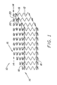
- an inventive innerspring assembly comprises a plurality of coil springs 12 (also referred to as “spring coils” or simply “springs”) arranged side-by-side in rows 14 and columns 16 to thereby form an innerspring assembly generally rectangular in shape.
- coil springs 12 also referred to as “spring coils” or simply “springs”
- rows 14 and columns 16 to thereby form an innerspring assembly generally rectangular in shape.
- cross-helical springs 20 and helical border wire springs 18 are coiled around convolutions of the individual spring coils, as described more particularly below.
- the cross-helical and helical attachments remain conventional, however, which is an advantage of the present invention.
- each coil spring 12 is composed of a single, continuous piece of wire stock which is generally helical in configuration and includes an upper terminal convolution or portion 22, a lower terminal convolution or portion 24, and a body portion made up of a number of turns of the wire stock.
- an attachment convolution 28, 30 for attaching adjacent coils to one another is formed on one of the turns of body portion inboard of a respective terminal convolution 22, 24.
- the springs 12 are arranged so that portions of the attachment convolutions 28 of adjacent coils overlap one another; it is these overlapping segments which are secured together by means of the cross-helical springs 20.
- upper terminal portion 22 is composed of a convolution of the helical coil which is substantially in the same plane AA.
- the lower terminal portion or convolution 24 has the same shape as the other end of the spring 12, and is similarly disposed in plane BB. When organized into a support surface, these terminal convolntions 22, 24 will occupy a common respective plane AA, BB
- Upper attachment convolutions 28 and lower attachment convolutions 30 are provided for allowing attachment of adjacent coils to one another. These attachment convolutions are also relatively flattened so that a major portion of the turn is in a respective common plane: CC in the case of upper attachment convolution 28 and plane DD in the case of lower attachment convolution 30.
- upper attachment convolutions 28 and lower attachment convolutions 30 have essentially the same shape as the terminal coils described in commonly-assigned patent U.S. 4,726,572, the disclosure of which is incorporated herein by reference.
- the terminal convolution described in that patent is moved inboard to a body turn of the inventive spring herein.
- these attachment convolutions are somewhat rectangular in shape, with first offset portions 32, second offset portions 34 and third offset portions 36 which are spaced radially (laterally) outwardly from the spring coil axis and from a cylindrical shape generally defined by the circular coils of the body portion.
- the third offset portions of the springs each have a stepped segment comprising a substantially straight major part 38 extending generally perpendicular to the first and second offset portions, and short parts 40 extending from the ends of the straight part to the remaining portions 42 of the third offset portions 36.
- Attachment convolutions of this structure are advantageously employed, for example, in securing the coils located on the periphery of the array to a border wire to prevent rotation of the third offset portion relative to the border wire, as described in the above noted U.S. 4,726,572.
- Adjacent spring coils are attached to one another by means of cross-helical springs 20 used to join the overlapped attachment convolution portions together. While overlapped segments are preferred, obviously spacing the attachment segments 32, 34 of adjacent springs closely together and joining them with the cross-helical springs 20 would also work, but is considered less desirable.
- the terminal convolution turn outboard of the attachment is left free, when an external pressure or force is applied thereto, these free ends can readily move off-axis of their respective spring (i.e., shift sideways) and independently of any other spring.
- the inventive innerspring assembly is more flexible in use, since action on one spring terminal convolution is not necessarily directly translated to an adjacent spring. It is considered that the surface of an innerspring having such "free" spring ends will adjust itself much more readily to diverse contours applied to the surface of the innerspring. The overall result can be greater comfort to the user.
- the mattress is considered to be more stable, long term, and is easier to manufacture than mattresses employing a pocketed spring design, since conventional manufacturing techniques using clips and cross-helicals are employed.
- the flexibility of an innerspring assembly embodying the present invention can be adjusted by varying the relative distance between planes AA and CC, between planes CC and DD, and between planes DD and BB, either individually or in combination.
- increasing the distance between planes AA and CC is considered to result in more flexibility of upper convolutions 22 relative to one another.
- innerspring assembly of the present invention can be used to make innerspring mattresses of any type.
- innerspring mattresses are typically made by covering at least the upper surface of the innerspring, defined by the upper terminal convolutions or portions of the coils, with insulators, flexible padding made from a flexible fabric or foam, ticking and the like.
- springs in the interior of the array are provided with attachment convolutions having the generally rectangular shape illustrated in U.S. 4,726,572.
- This shape with the third offset allows adjacent interior coils to be secured together in pairs by helical springs in a transverse direction (i.e., in the direction of columns 16 of FIG. 1) in addition to longitudinally in the direction of rows 14.
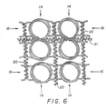
- This can be done as shown in FIG. 6 by arranging adjacent springs in a row 14 in pairs, with the coils in each pair in mirror-image relation with one another so that the third offset portions 36 of the attachment convolutions of each spring pair overlap one another.
- individual springs 12 can be made from multiple pieces rather than a single, continuous piece of wire as shown in the illustrated embodiments.
- terminal portions of springs in the innerspring could be loosely interconnected one to another, as by various engagements of the same to an insulator applied over the innerspring surface. Such an engagement would not defeat the free movement of the remainder of the terminal portions with respect to one another. So long as the majority of the terminal portions of the springs are free to move independently of one another in the axial direction, i.e., in the direction of the respective axes of the spring helixes, the advantages of the invention should be realized. All such modifications are intended to be included within the scope of the present invention.
Landscapes
- Engineering & Computer Science (AREA)
- Mechanical Engineering (AREA)
- Springs (AREA)
- Mattresses And Other Support Structures For Chairs And Beds (AREA)
- Connections Arranged To Contact A Plurality Of Conductors (AREA)
- Magnetic Heads (AREA)
Abstract
Description
- The present invention relates to a helical spring for use in an innerspring assembly, and to an innerspring and a mattress innerspring containing such springs.
- Innerspring assemblies are conventionally made from arrays of vertically-oriented coil springs (i.e., the longitudinal axes of the typical helical springs are perpendicular to the innerspring support surface). The springs are arranged in a generally side-by-side arrangement, usually in parallel columns and parallel rows, to form a support surface. To secure the individual spring coils together and thereby form a unitary innerspring assembly, some form of attachment means is normally employed such as clips, cross-helical springs and the like. Usually adjacent springs are attached together at their terminal convolutions, i.e., the metal turn at the very top and bottom of the springs. See, for example, Bell U.S. 2,611,910, and particularly Flesher et.al. U.S. 4,726,572.
- Another design for uniting coil springs in an innerspring assembly employs pocketed coil springs, i.e., individual coil springs which are each encased in a "cell" made from fabric or other flexible material. To form an integral innerspring assembly for these pocketed coil springs, the individual flexible covers of the pocketed coil springs are attached to one another by sewing, strings, hot melt adhesives or other means. The springs themselves are, however, typically not interconnected except through this joining of their pockets.
- Each of these designs has its own advantages. For example, the pocketed coil design offers a degree of mobility between individual springs, in particular because the terminal convolutions of adjacent coils are not directly secured together. A certain amount of "float" between springs is therefore available. Conventional designs using clipped or otherwise wire-joined spring ends tend to offer superior longevity and ease of manufacture, in part because the use of fabrics is eliminated.
- GB-380,582 discloses a spring having a main body portion with end coil turns which are connected to adjacent springs, and terminal convolutions extending from the ends of the main body portion and having a smaller diameter than the main body portion.
- US-2,480,158 discloses a spring in accordance with the pre-characterising portion of claim 1.
- According to the present invention, there is provided a helical spring for use in an innerspring assembly made from a plurality of said springs, said spring comprising a compressible body portion comprised of a plurality of coil turns, and two offset segments formed on opposite sides of a first coil turn of said body portion, said offset segments having straight portions which are generally parallel to and laterally outboard from a tangent to a cylindrical shape generally defined by the turns of said body portion, said offset segments being located in substantially the same plane which is perpendicular to a longitudinal axis defined by said cylindrical shape, said offset segments being adapted for engagement with means for interconnecting a plurality of said springs in the innerspring assembly;
wherein: - said spring further comprises a first terminal convolution at one end of said body portion;
- said first coil turn of said body portion is at said one end of said body portion;
- said first coil turn has a diameter which is generally coplanar with said two offset segments;
- said first coil turn is spaced from said first terminal convolution; and
- said offset segments are arranged such that said first terminal convolution and a first turn inboard from said first terminal convolution remain free of said interconnecting means when said spring is in the innerspring assembly; characterized in that said first terminal convolution has a diameter which is at least as great as that of said first coil turn such that said terminal convolution cannot pass through said plane upon compression of said spring along said longitudinal axis.
-
- This free end construction has the ability to readily move in response to a load, which is particularly advantageous if the load is off-axis (such as a load with a lateral component relative to the support surface). A "free-floating" support surface is therefore available by connecting such springs to form an innerspring assembly, yet the springs themselves can be joined together in a very stable array using conventional manufacturing techniques (e.g., cross-helical connections).
- By connecting the springs at points inboard from the terminal convolution, the terminal convolution and the intermediate turn(s) remain free of the interconnecting means when the springs are in the innerspring assembly. This yields a free end for the spring, which provides the noted "float" to the spring end, and flexibility to the support surface that the spring ends define for the innerspring. Depending on where the engagement is made along the body portions of adjacent springs in the innerspring, the "float" or flexibility can be thereby adjusted.
- Because helical springs are generally manufactured with axial symmetry, a preferred embodiment of the spring further comprises a second terminal convolution at the other end of said body portion, said spring further comprising two offset segments formed on opposite sides of a second coil turn of said body portion, said offset segments on said second coil turn having straight portions which are generally parallel to and laterally outboard from a tangent to said cylindrical shape, said offset segments on said second coil turn being located in substantially the same plane which is perpendicular to said longitudinal axis defined by said cylindrical shape, said offset segments being adapted for engagement with means for interconnecting a plurality of said springs in the innerspring assembly such that said second terminal convolution and a second turn inboard from said second terminal convolution remain free of said interconnecting means when said spring is in the innerspring assembly.
- Preferably, said first coil turn has a third offset segment located between said first and second offset segments, said third offset segment having a straight portion tangential to said cylindrical shape defined by the turns of said body portion. Usually, said body portion defines an attachment coil at each end of said spring, each attachment coil being spaced from a respective terminal convolution, the first, second, and third offset segments of each attachment coil being located in substantially the same plane which is perpendicular to said longitudinal axis defined by said cylindrical shape. For example, each attachment coil is the second turn inboard from a respective terminal convolution.
- In an embodiment of the invention, an innerspring is an array of helical coil springs arranged in orthogonal rows and columns. The offset segments may be overlapped and then laced together using a small diameter cross-helical spring.
- The springs are attached to each other at the offset segments at a point spaced axially inboard from the end of the spring. The manufacturing techniques for applying the cross-helicals for joining the springs remain virtually unchanged. The terminal convolutions of adjacent springs are not attached to one another, leaving the spring ends free to act independently of one another in response to an applied load. As a result, the upper surface of the innerspring is far more flexible and responsive to contour differences (i.e., a body lying thereon) than conventional pocketless designs in which the upper terminal convolutions are attached to one another, where the displacement of one spring in turn fairly immediately involves displacement of adjacent springs to which its terminal convolution is joined. The overall result achieved by the free-end innerspring of the present invention can be an improvement in comfort with all the advantages of "hard-wired" spring designs.
- The foregoing features and advantages of the present invention will be further understood upon consideration of the following detailed description of certain embodiments of the present invention with reference to the accompanying drawings.
-
- FIG. 1 is a schematic pictorial view of an innerspring assembly made in accordance with the present invention;
- FIG. 2 is a plan view of a section of an innerspring assembly such as shown in FIG. 1 illustrating the attachment of a number of spring coils located in the interior of the inventive innerspring assembly;
- FIG. 3 is an elevational view taken along line 3-3 of FIG. 2;
- FIG. 4 is another elevational view taken along line 4-4 of FIG. 3 showing two adjacent springs joined together;
- FIG. 5 is a view similar to FIG. 2 illustrating specific features of one set of overlapped offset portions of the attachment convolutions in accordance with a preferred embodiment of the invention; and
- FIG. 6 is a view similar to FIG. 2 illustrating another embodiment of the invention in which coil springs are arranged in mirror-image relation and secured together along transverse directions.
-
- As shown in FIG. 1, an inventive innerspring assembly, generally indicated at 10, comprises a plurality of coil springs 12 (also referred to as "spring coils" or simply "springs") arranged side-by-side in
rows 14 andcolumns 16 to thereby form an innerspring assembly generally rectangular in shape. The foregoing would represent a typical mattress innerspring, for example. While the embodiments discussed hereafter will generally relate to such a mattress innerspring, it will nonetheless be understood that the invention has application in other environments and other innerspring assemblies, such as furniture cushions and the like. Also, the reference to "rows" and "columns" herein is not meant to be limiting, since the terms could be used interchangeably depending on the point of reference taken. - To hold the
springs 12 in place and make an integral assembly,cross-helical springs 20 and helicalborder wire springs 18 are coiled around convolutions of the individual spring coils, as described more particularly below. The cross-helical and helical attachments remain conventional, however, which is an advantage of the present invention. - As illustrated in FIGS. 3 and 4, for example, each
coil spring 12 is composed of a single, continuous piece of wire stock which is generally helical in configuration and includes an upper terminal convolution orportion 22, a lower terminal convolution orportion 24, and a body portion made up of a number of turns of the wire stock. With particular reference to Figs. 2 and 4, anattachment convolution terminal convolution springs 12 are arranged so that portions of theattachment convolutions 28 of adjacent coils overlap one another; it is these overlapping segments which are secured together by means of thecross-helical springs 20. - In the embodiments shown,
upper terminal portion 22 is composed of a convolution of the helical coil which is substantially in the same plane AA. Likewise, the lower terminal portion orconvolution 24 has the same shape as the other end of thespring 12, and is similarly disposed in plane BB. When organized into a support surface, theseterminal convolntions -
Upper attachment convolutions 28 andlower attachment convolutions 30 are provided for allowing attachment of adjacent coils to one another. These attachment convolutions are also relatively flattened so that a major portion of the turn is in a respective common plane: CC in the case ofupper attachment convolution 28 and plane DD in the case oflower attachment convolution 30. - Preferably, upper attachment convolutions 28 and
lower attachment convolutions 30 have essentially the same shape as the terminal coils described in commonly-assigned patent U.S. 4,726,572, the disclosure of which is incorporated herein by reference. In essence, the terminal convolution described in that patent is moved inboard to a body turn of the inventive spring herein. As illustrated in FIGS. 2 and 6, these attachment convolutions are somewhat rectangular in shape, with first offsetportions 32, second offset portions 34 and third offset portions 36 which are spaced radially (laterally) outwardly from the spring coil axis and from a cylindrical shape generally defined by the circular coils of the body portion. The third offset portions of the springs, or at least those of the springs located on the periphery of the array, each have a stepped segment comprising a substantially straightmajor part 38 extending generally perpendicular to the first and second offset portions, andshort parts 40 extending from the ends of the straight part to the remainingportions 42 of the third offset portions 36. Attachment convolutions of this structure are advantageously employed, for example, in securing the coils located on the periphery of the array to a border wire to prevent rotation of the third offset portion relative to the border wire, as described in the above noted U.S. 4,726,572. - Adjacent spring coils, as illustrated in FIG. 2 through 4, are attached to one another by means of
cross-helical springs 20 used to join the overlapped attachment convolution portions together. While overlapped segments are preferred, obviously spacing theattachment segments 32, 34 of adjacent springs closely together and joining them with the cross-helical springs 20 would also work, but is considered less desirable. - Since the terminal convolution turn outboard of the attachment is left free, when an external pressure or force is applied thereto, these free ends can readily move off-axis of their respective spring (i.e., shift sideways) and independently of any other spring. As a result, the inventive innerspring assembly is more flexible in use, since action on one spring terminal convolution is not necessarily directly translated to an adjacent spring. It is considered that the surface of an innerspring having such "free" spring ends will adjust itself much more readily to diverse contours applied to the surface of the innerspring. The overall result can be greater comfort to the user. Moreover, since encasement fabrics are not involved as in pocketed springs, the mattress is considered to be more stable, long term, and is easier to manufacture than mattresses employing a pocketed spring design, since conventional manufacturing techniques using clips and cross-helicals are employed.
- In accordance with still another feature of the invention, the flexibility of an innerspring assembly embodying the present invention -- in other words the degree to which the upper portions or
convolutions 22 of adjacent springs are free to move independently of one another -- can be adjusted by varying the relative distance between planes AA and CC, between planes CC and DD, and between planes DD and BB, either individually or in combination. Thus, for example, increasing the distance between planes AA and CC is considered to result in more flexibility ofupper convolutions 22 relative to one another. Adjustment of the distances between the different planes, and locating the interconnection planes with one, two or even more turns outboard from the same, yields a spring assembly which can be made having a desired degree of flexibility from a broad range of possible choices. - The innerspring assembly of the present invention can be used to make innerspring mattresses of any type. As well appreciated in the art, innerspring mattresses are typically made by covering at least the upper surface of the innerspring, defined by the upper terminal convolutions or portions of the coils, with insulators, flexible padding made from a flexible fabric or foam, ticking and the like.
- In the embodiment depicted in FIG. 6, springs in the interior of the array are provided with attachment convolutions having the generally rectangular shape illustrated in U.S. 4,726,572. This shape with the third offset allows adjacent interior coils to be secured together in pairs by helical springs in a transverse direction (i.e., in the direction of
columns 16 of FIG. 1) in addition to longitudinally in the direction ofrows 14. This can be done as shown in FIG. 6 by arranging adjacent springs in arow 14 in pairs, with the coils in each pair in mirror-image relation with one another so that the third offset portions 36 of the attachment convolutions of each spring pair overlap one another. - Accordingly, while some embodiments of the present invention have been illustrated above, it should be appreciated that many modifications can be made without departing from the scope of the invention. For example, although the above illustrates cross-helical springs being used for attaching adjacent coils together, any attachment means can be used. For example, clips as illustrated in the above noted Bell patent can be employed. Also, the
terminal portions - Furthermore, the individual springs 12 can be made from multiple pieces rather than a single, continuous piece of wire as shown in the illustrated embodiments.
- Finally, it is also within the scope of the invention that some terminal portions of springs in the innerspring could be loosely interconnected one to another, as by various engagements of the same to an insulator applied over the innerspring surface. Such an engagement would not defeat the free movement of the remainder of the terminal portions with respect to one another. So long as the majority of the terminal portions of the springs are free to move independently of one another in the axial direction, i.e., in the direction of the respective axes of the spring helixes, the advantages of the invention should be realized. All such modifications are intended to be included within the scope of the present invention.
Claims (11)
- A helical spring (12) for use in an innerspring assembly (10) made from a plurality of said springs, said spring comprising a compressible body portion comprised of a plurality of coil turns, and two offset segments (32,34) formed on opposite sides of a first coil turn (28) of said body portion, said offset segments (32,34) having straight portions which are generally parallel to and laterally outboard from a tangent to a cylindrical shape generally defined by the turns of said body portion, said offset segments (32,34) being located in substantially the same plane which is perpendicular to a longitudinal axis defined by said cylindrical shape, said offset segments (32,34) being adapted for engagement with means (20) for interconnecting a plurality of said springs (12) in the innerspring assembly;
wherein:characterized in that said first terminal convolution (22) has a diameter which is at least as great as that of said first coil turn (28) such that said terminal convolution (22) cannot pass through said plane upon compression of said spring (12) along said longitudinal axis.said spring (12) further comprises a first terminal convolution (22) at one end of said body portion;said first coil turn (28) of said body portion is at said one end of said body portion;said first coil turn (28) has a diameter which is generally coplanar with said two offset segments (32,34);said first coil turn (28) is spaced from said first terminal convolution (22); andsaid offset segments (32,34) are arranged such that said first terminal convolution (22) and a first turn inboard from said first terminal convolution remain free of said interconnecting means (20) when said spring (12) is in the innerspring assembly (10); - The spring of Claim 1 wherein said spring (12) further comprises a second terminal convolution (24) at the other end of said body portion, said spring further comprising two offset segments (32,34) formed on opposite sides of a second coil turn (30) of said body portion, said offset segments (32,34) on said second coil turn (30) having straight portions which are generally parallel to and laterally outboard from a tangent to said cylindrical shape, said offset segments (32,34) on said second coil turn (30) being located in substantially the same plane which is perpendicular to said longitudinal axis defined by said cylindrical shape, said offset segments (32,34) being adapted for engagement with means for interconnecting (20) a plurality of said springs (12) in the innerspring assembly such that said second terminal convolution (24) and a second turn inboard from said second terminal convolution remain free of said interconnecting means (20) when said spring (12) is in the innerspring assembly (10).
- The spring of Claim 1 wherein said first coil turn (28) has a third offset segment (36) located between said first and second offset segments (32,34), said third offset segment (36) having a straight portion (38) tangential to said cylindrical shape defined by the turns of said body portion.
- The spring of Claim 3 wherein said body portion defines an attachment coil (28,30) at each end of said spring (12), each attachment coil (28,30) being spaced from a respective terminal convolution (22,24), the first, second, and third offset segments (32,34,36) of each attachment coil (28,30) being located in substantially the same plane which is perpendicular to said longitudinal axis defined by said cylindrical shape.
- The spring of Claim 4 wherein each attachment coil (28,30) is the second turn inboard from a respective terminal convolution (22,24).
- An innerspring (10) comprising:a plurality of helical springs (12) each according to Claim 1 or 2, said springs (12) being organized into an array and defining a support surface to said innerspring, andmeans (20) interconnecting said springs (12) into said array.
- The innerspring of Claim 6 wherein said springs (12) are organized into an array of orthogonal rows (14) and columns (16) and define support surfaces to said innerspring on top and bottom sides thereof,
wherein said interconnecting means is a cross-helical spring (20), and
wherein said springs (12) are located in said array such that offset segments (32,34) of springs in adjacent rows are parallel and close together in said array with said cross-helical spring (20) surrounding and joining said close together offset segments (32,34) along said rows (14). - The innerspring of Claim 7 wherein the offset segments (32,34) of adjacent springs (12) are overlapped.
- The innerspring of Claim 7 wherein said springs (12) each further include a third offset segment (36) which is generally perpendicular to said other two offset segments (32,34) at said one end of said body portion, with said springs being further located in said array such that said third offset segments (36) of springs in adjacent columns (16) are parallel and close together in said array with a second cross-helical spring (21) surrounding and joining said close together third offset segments (36) along said columns.
- A mattress innerspring (10) comprising:a plurality of helical springs (12) organized into an array of orthogonal rows (14) and columns (16), each said spring (12) being according to any one of Claims 3 to 5; andmeans (20) interconnecting a plurality of said springs (12) by connecting the close-together offset segments (32,34) of pairs of springs together.
- The mattress innerspring of Claim 10 wherein said interconnecting means comprises cross-helical springs (20).
Applications Claiming Priority (3)
| Application Number | Priority Date | Filing Date | Title |
|---|---|---|---|
| US32702394A | 1994-10-21 | 1994-10-21 | |
| US327023 | 1994-10-21 | ||
| PCT/US1995/013263 WO1996012428A1 (en) | 1994-10-21 | 1995-10-20 | Innerspring construction with springs having free terminal convolutions |
Publications (4)
| Publication Number | Publication Date |
|---|---|
| EP0794720A1 EP0794720A1 (en) | 1997-09-17 |
| EP0794720A4 EP0794720A4 (en) | 2000-06-07 |
| EP0794720B1 true EP0794720B1 (en) | 2005-02-02 |
| EP0794720B8 EP0794720B8 (en) | 2005-06-29 |
Family
ID=23274799
Family Applications (1)
| Application Number | Title | Priority Date | Filing Date |
|---|---|---|---|
| EP95938759A Expired - Lifetime EP0794720B8 (en) | 1994-10-21 | 1995-10-20 | Helical spring for an innerspring assembly and an innerspring and a matress innerspring containing such springs |
Country Status (14)
| Country | Link |
|---|---|
| US (1) | US5713088A (en) |
| EP (1) | EP0794720B8 (en) |
| JP (2) | JPH10509347A (en) |
| KR (1) | KR100355167B1 (en) |
| CN (1) | CN1209061C (en) |
| AT (1) | ATE288215T1 (en) |
| BR (1) | BR9509412A (en) |
| DE (1) | DE69533990T8 (en) |
| DK (1) | DK0794720T3 (en) |
| ES (1) | ES2236717T3 (en) |
| IL (1) | IL115704A (en) |
| NZ (1) | NZ296267A (en) |
| WO (1) | WO1996012428A1 (en) |
| ZA (1) | ZA958901B (en) |
Families Citing this family (37)
| Publication number | Priority date | Publication date | Assignee | Title |
|---|---|---|---|---|
| AU715385B2 (en) * | 1996-07-30 | 2000-02-03 | Sleep Haven Bedding Co Pty Ltd | Spring assembly for mattress |
| USD409024S (en) * | 1998-02-02 | 1999-05-04 | Ohio Mattress Company Licensing and Components Group, Inc. | Mattress innerspring |
| US6128798A (en) | 1998-09-04 | 2000-10-10 | Sealy Technology Llc | Cavitated pad and innerspring assembly combination having springs with free terminal convolutions |
| US6256820B1 (en) * | 2000-02-09 | 2001-07-10 | L&P Property Management Company | Multilayered pocketed bedding or seating product |
| US6658682B1 (en) | 2000-04-25 | 2003-12-09 | L&P Property Management Company | Bedding or seating product with spring core topper |
| US6353952B1 (en) | 2000-05-31 | 2002-03-12 | L&P Property Management Company | Posturized bedding or seating product with springs of differing heights |
| US6263533B1 (en) | 2000-06-02 | 2001-07-24 | Sealy Technology Llc | Extruded foam reinforcement structures for innerspring assemblies and mattresses |
| KR100503556B1 (en) * | 2003-01-07 | 2005-07-25 | 주식회사 에이스침대 | Structure and Mnaufacture method of pocket spring set using in matress |
| US6983503B2 (en) * | 2003-09-09 | 2006-01-10 | Ace Bed Co., Ltd. | Apparatus for packing free terminal convolutions of spring assembly used in mattress |
| US6931685B2 (en) * | 2003-09-12 | 2005-08-23 | Dreamwell, Ltd. | One-sided mattress |
| US7404223B2 (en) * | 2004-08-28 | 2008-07-29 | Sealy Technology Llc | Innerspring coils and innersprings with non-helical segments |
| US7178187B2 (en) * | 2004-08-28 | 2007-02-20 | Sealy Technology Llc | Asymmetric spring components and innersprings for one-sided mattresses |
| DE102005053123A1 (en) * | 2005-11-08 | 2007-05-10 | Agro Federkernproduktions Gmbh | innerspring |
| KR100717543B1 (en) * | 2006-03-14 | 2007-05-15 | 주식회사 에이스침대 | Spring structure for bed mattress |
| KR100717535B1 (en) * | 2006-04-07 | 2007-05-15 | 주식회사 에이스침대 | Spring for bed mattress with anti-contact and rigid reinforcement structure |
| USD652235S1 (en) | 2010-12-16 | 2012-01-17 | Sealy Technology Llc | Coil |
| USD651828S1 (en) | 2010-12-16 | 2012-01-10 | Sealy Technology Llc | Coil |
| US9022369B2 (en) * | 2011-01-20 | 2015-05-05 | Sealy Technology, Llc | Reverse coil head coils and innersprings |
| GB2495499B (en) * | 2011-10-11 | 2019-02-06 | Hs Products Ltd | Hybrid spring |
| EP2689695B1 (en) | 2012-07-26 | 2016-06-08 | L & P Swiss Holding AG | Spring core |
| USD739162S1 (en) | 2012-08-22 | 2015-09-22 | L&P Swiss Holding Ag | Coil spring |
| JPWO2014115750A1 (en) * | 2013-01-24 | 2017-01-26 | 五光発條株式会社 | Spring assembly |
| KR101355896B1 (en) * | 2013-03-28 | 2014-01-28 | 안유수 | Coil spring of bed matress with means for preventing the friction noise |
| KR101410355B1 (en) * | 2013-09-25 | 2014-06-24 | 안유수 | High tension coil spring of bed matress with means for preventing the friction noise |
| KR101410357B1 (en) * | 2013-09-25 | 2014-07-02 | 안유수 | High tension coil spring of bed matress with means for preventing the friction noise |
| CN104643727B (en) * | 2013-11-18 | 2017-04-12 | 许汉忠 | Spring mattress |
| US11076705B2 (en) | 2014-05-30 | 2021-08-03 | Sealy Technology, Llc | Spring core with integrated cushioning layer |
| CN104455135A (en) * | 2014-12-09 | 2015-03-25 | 常州特斯克车镜有限公司 | Spiral spring |
| US11033114B2 (en) | 2015-12-17 | 2021-06-15 | Sealy Technology, Llc | Coil-in-coil spring with variable loading response and mattresses including the same |
| CN108697242B (en) | 2016-01-21 | 2021-08-20 | 丝涟科技有限责任公司 | Coil-in-coil spring with nonlinear load response and cushion including the same |
| US10598242B2 (en) | 2016-05-20 | 2020-03-24 | Sealy Technology, Llc | Coil springs with non-linear loading responses and mattresses including the same |
| MX2019006917A (en) | 2016-12-15 | 2019-08-22 | Sealy Technology Llc | OPEN COIL SPRING ASSEMBLIES. |
| CN107387630A (en) * | 2017-06-29 | 2017-11-24 | 太仓市惠得利弹簧有限公司 | A kind of tower hook spring group |
| EP3703537B1 (en) | 2017-10-31 | 2024-06-26 | Sealy Technology, LLC | Pocket coil spring assembly including flexible foam |
| KR102635827B1 (en) * | 2018-02-09 | 2024-02-13 | 마다드 피티와이 엘티디 | Wire coil and inner spring system |
| CN108930738A (en) * | 2018-10-02 | 2018-12-04 | 湖州杭佳弹簧有限公司 | Single load bearing spring |
| CN120720354A (en) * | 2024-03-29 | 2025-09-30 | 厦门新技术集成有限公司 | A spring with a positioning ring and an elastic pad |
Family Cites Families (29)
| Publication number | Priority date | Publication date | Assignee | Title |
|---|---|---|---|---|
| US184703A (en) * | 1876-11-28 | Improvement in bed-bottoms | ||
| US137030A (en) * | 1873-03-18 | Improvement in mattresses | ||
| US1211267A (en) * | 1916-02-11 | 1917-01-02 | Leonard A Young | Seat-spring. |
| US1337320A (en) * | 1919-05-17 | 1920-04-20 | Karr Francis | Spring-mattress |
| US1798885A (en) * | 1925-06-01 | 1931-03-31 | Karr Francis | Spring cushion |
| CH155726A (en) * | 1930-11-08 | 1932-07-15 | Hueser Schlaraffia Werke | Padding for mattresses, pillows, upholstered furniture or the like. |
| US1950770A (en) * | 1931-01-03 | 1934-03-13 | Simmons Co | Inner spring construction for matresses and the like |
| US1907324A (en) * | 1932-05-13 | 1933-05-02 | Leggett And Platt Spring Bed A | Spring bed bottom |
| US1938489A (en) * | 1932-06-20 | 1933-12-05 | Charles D Karr | Spring assembly |
| US1989302A (en) * | 1933-05-10 | 1935-01-29 | William H Wilmot | Spring structure |
| US2054868A (en) * | 1935-04-22 | 1936-09-22 | Schwartzman Jacob | Bedspring |
| GB494428A (en) * | 1937-05-01 | 1938-10-26 | Albert James Ludlam | Improvements in spring mattresses and the like |
| US2214135A (en) * | 1939-11-21 | 1940-09-10 | Leggett And Platt Spring Bed A | Spring structure for use in bed mattresses, pillows, and cushions |
| US2348897A (en) * | 1942-06-06 | 1944-05-16 | Gladstone Benjamin | Spring for beds or mattresses |
| US2480158A (en) * | 1945-07-23 | 1949-08-30 | David T Owen | Spring and spring construction |
| US2562099A (en) * | 1948-05-18 | 1951-07-24 | Hilton John | Spring assembly |
| US2611910A (en) * | 1949-06-30 | 1952-09-30 | Bell Sam | Mattress coil spring unit |
| US2617124A (en) * | 1949-10-06 | 1952-11-11 | Gustave P Johnson | Spring unit for mattresses, cushions, and the like |
| US3107367A (en) * | 1960-11-21 | 1963-10-22 | Jr Fred A Nachman | Bed spring assembly |
| US3089154A (en) * | 1961-03-09 | 1963-05-14 | Truman C Boyles | Mattress construction having different degrees of firmness |
| US3533114A (en) * | 1968-07-12 | 1970-10-13 | Holland Wire Products Co Inc | Coil spring configuration |
| US4122566A (en) * | 1977-03-16 | 1978-10-31 | Steadley Company, Inc. | Foundation unit having a posturized inner border |
| CH658778A5 (en) * | 1982-06-28 | 1986-12-15 | Spuehl Ag | SPRING CORE FOR A MATTRESS. |
| DE3333846A1 (en) * | 1983-09-20 | 1985-04-04 | Spühl AG, St. Gallen | SPRING CORE FOR A MATTRESS |
| US4566926A (en) * | 1984-03-09 | 1986-01-28 | Simmons U.S.A. Corporation | Method and apparatus for manufacturing innerspring constructions |
| US4578834A (en) * | 1984-03-09 | 1986-04-01 | Simmons U.S.A. Corporation | Innerspring construction |
| US4726572A (en) * | 1986-05-16 | 1988-02-23 | Sealy, Incorporated | Spring coil and spring assembly |
| US4781360A (en) * | 1987-12-07 | 1988-11-01 | Webster Spring Co. Inc. | Spring assembly with helical coils of spring wire with unknotted ends |
| US4960267A (en) * | 1989-05-26 | 1990-10-02 | Leggett & Platt, Incorporated | Edge-reinforced spring bedding product |
-
1995
- 1995-10-20 DE DE69533990T patent/DE69533990T8/en active Active
- 1995-10-20 AT AT95938759T patent/ATE288215T1/en not_active IP Right Cessation
- 1995-10-20 IL IL11570495A patent/IL115704A/en not_active IP Right Cessation
- 1995-10-20 NZ NZ296267A patent/NZ296267A/en not_active IP Right Cessation
- 1995-10-20 KR KR1019970702616A patent/KR100355167B1/en not_active Expired - Fee Related
- 1995-10-20 CN CNB951957910A patent/CN1209061C/en not_active Expired - Lifetime
- 1995-10-20 JP JP8514019A patent/JPH10509347A/en active Pending
- 1995-10-20 ES ES95938759T patent/ES2236717T3/en not_active Expired - Lifetime
- 1995-10-20 ZA ZA958901A patent/ZA958901B/en unknown
- 1995-10-20 EP EP95938759A patent/EP0794720B8/en not_active Expired - Lifetime
- 1995-10-20 BR BR9509412A patent/BR9509412A/en not_active IP Right Cessation
- 1995-10-20 DK DK95938759T patent/DK0794720T3/en active
- 1995-10-20 WO PCT/US1995/013263 patent/WO1996012428A1/en not_active Ceased
-
1997
- 1997-04-08 US US08/835,544 patent/US5713088A/en not_active Expired - Lifetime
-
2005
- 2005-10-26 JP JP2005312039A patent/JP2006095323A/en not_active Withdrawn
Also Published As
| Publication number | Publication date |
|---|---|
| KR100355167B1 (en) | 2002-12-16 |
| BR9509412A (en) | 1998-11-03 |
| DE69533990D1 (en) | 2005-03-10 |
| EP0794720A1 (en) | 1997-09-17 |
| ES2236717T3 (en) | 2005-07-16 |
| IL115704A (en) | 1998-10-30 |
| IL115704A0 (en) | 1996-01-19 |
| CN1161639A (en) | 1997-10-08 |
| JPH10509347A (en) | 1998-09-14 |
| ZA958901B (en) | 1996-08-15 |
| WO1996012428A1 (en) | 1996-05-02 |
| DE69533990T2 (en) | 2006-03-16 |
| DK0794720T3 (en) | 2005-05-09 |
| DE69533990T8 (en) | 2006-11-16 |
| US5713088A (en) | 1998-02-03 |
| EP0794720B8 (en) | 2005-06-29 |
| EP0794720A4 (en) | 2000-06-07 |
| ATE288215T1 (en) | 2005-02-15 |
| NZ296267A (en) | 1999-03-29 |
| CN1209061C (en) | 2005-07-06 |
| JP2006095323A (en) | 2006-04-13 |
Similar Documents
| Publication | Publication Date | Title |
|---|---|---|
| US5713088A (en) | Innerspring construction with springs having free terminal convolutions | |
| EP0269681B1 (en) | Spring coil and spring assembly | |
| US5127635A (en) | Pocketed continuous wire multiple coil spring bedding product | |
| US4790038A (en) | Bedding spring assembly | |
| KR0169951B1 (en) | Spring bedding product | |
| US6338174B1 (en) | Spring mattress | |
| US4369534A (en) | Center reinforced mattress | |
| US5649332A (en) | Posturized continuous mattress spring core | |
| US4790519A (en) | Borderwire hinge clip | |
| EP0989814B1 (en) | Spring mattress | |
| US4124041A (en) | Method of assembling coil springs | |
| KR100372273B1 (en) | an innerspring assembly for mattress | |
| GB2198938A (en) | A spring interior for a double mattress | |
| WO1988005640A1 (en) | Bedding spring assembly |
Legal Events
| Date | Code | Title | Description |
|---|---|---|---|
| PUAI | Public reference made under article 153(3) epc to a published international application that has entered the european phase |
Free format text: ORIGINAL CODE: 0009012 |
|
| 17P | Request for examination filed |
Effective date: 19970520 |
|
| AK | Designated contracting states |
Kind code of ref document: A1 Designated state(s): AT BE CH DE DK ES FR GB GR IE IT LI NL SE |
|
| A4 | Supplementary search report drawn up and despatched |
Effective date: 20000427 |
|
| AK | Designated contracting states |
Kind code of ref document: A4 Designated state(s): AT BE CH DE DK ES FR GB GR IE IT LI NL SE |
|
| RIC1 | Information provided on ipc code assigned before grant |
Free format text: 7A 47C 23/02 A, 7A 47C 23/04 B, 7A 47C 27/04 B, 7F 16F 3/00 B, 7F 16F 3/04 B, 7A 47C 27/06 B, 7A 47C 23/05 B |
|
| 17Q | First examination report despatched |
Effective date: 20020325 |
|
| GRAP | Despatch of communication of intention to grant a patent |
Free format text: ORIGINAL CODE: EPIDOSNIGR1 |
|
| GRAS | Grant fee paid |
Free format text: ORIGINAL CODE: EPIDOSNIGR3 |
|
| GRAA | (expected) grant |
Free format text: ORIGINAL CODE: 0009210 |
|
| AK | Designated contracting states |
Kind code of ref document: B1 Designated state(s): AT BE CH DE DK ES FR GB GR IE IT LI NL SE |
|
| PG25 | Lapsed in a contracting state [announced via postgrant information from national office to epo] |
Ref country code: NL Free format text: LAPSE BECAUSE OF FAILURE TO SUBMIT A TRANSLATION OF THE DESCRIPTION OR TO PAY THE FEE WITHIN THE PRESCRIBED TIME-LIMIT Effective date: 20050202 Ref country code: BE Free format text: LAPSE BECAUSE OF FAILURE TO SUBMIT A TRANSLATION OF THE DESCRIPTION OR TO PAY THE FEE WITHIN THE PRESCRIBED TIME-LIMIT Effective date: 20050202 Ref country code: AT Free format text: LAPSE BECAUSE OF FAILURE TO SUBMIT A TRANSLATION OF THE DESCRIPTION OR TO PAY THE FEE WITHIN THE PRESCRIBED TIME-LIMIT Effective date: 20050202 |
|
| REG | Reference to a national code |
Ref country code: GB Ref legal event code: FG4D |
|
| REG | Reference to a national code |
Ref country code: CH Ref legal event code: EP |
|
| REG | Reference to a national code |
Ref country code: IE Ref legal event code: FG4D |
|
| REF | Corresponds to: |
Ref document number: 69533990 Country of ref document: DE Date of ref document: 20050310 Kind code of ref document: P |
|
| PG25 | Lapsed in a contracting state [announced via postgrant information from national office to epo] |
Ref country code: GR Free format text: LAPSE BECAUSE OF FAILURE TO SUBMIT A TRANSLATION OF THE DESCRIPTION OR TO PAY THE FEE WITHIN THE PRESCRIBED TIME-LIMIT Effective date: 20050502 |
|
| RTI2 | Title (correction) |
Free format text: HELICAL SPRING FOR AN INNERSPRING ASSEMBLY AND AN INNERSPRING AND A MATRESS INNERSPRING CONTAINING SUCH SPRINGS |
|
| REG | Reference to a national code |
Ref country code: DK Ref legal event code: T3 |
|
| REG | Reference to a national code |
Ref country code: SE Ref legal event code: TRGR |
|
| REG | Reference to a national code |
Ref country code: CH Ref legal event code: NV Representative=s name: MICHELI & CIE INGENIEURS-CONSEILS |
|
| REG | Reference to a national code |
Ref country code: ES Ref legal event code: FG2A Ref document number: 2236717 Country of ref document: ES Kind code of ref document: T3 |
|
| NLV1 | Nl: lapsed or annulled due to failure to fulfill the requirements of art. 29p and 29m of the patents act | ||
| PG25 | Lapsed in a contracting state [announced via postgrant information from national office to epo] |
Ref country code: IE Free format text: LAPSE BECAUSE OF NON-PAYMENT OF DUE FEES Effective date: 20051020 |
|
| PLBE | No opposition filed within time limit |
Free format text: ORIGINAL CODE: 0009261 |
|
| STAA | Information on the status of an ep patent application or granted ep patent |
Free format text: STATUS: NO OPPOSITION FILED WITHIN TIME LIMIT |
|
| ET | Fr: translation filed | ||
| 26N | No opposition filed |
Effective date: 20051103 |
|
| REG | Reference to a national code |
Ref country code: IE Ref legal event code: MM4A |
|
| PGFP | Annual fee paid to national office [announced via postgrant information from national office to epo] |
Ref country code: CH Payment date: 20070912 Year of fee payment: 13 |
|
| PGFP | Annual fee paid to national office [announced via postgrant information from national office to epo] |
Ref country code: DK Payment date: 20071004 Year of fee payment: 13 |
|
| PGFP | Annual fee paid to national office [announced via postgrant information from national office to epo] |
Ref country code: SE Payment date: 20071017 Year of fee payment: 13 |
|
| REG | Reference to a national code |
Ref country code: CH Ref legal event code: PL |
|
| REG | Reference to a national code |
Ref country code: DK Ref legal event code: EBP |
|
| EUG | Se: european patent has lapsed | ||
| PG25 | Lapsed in a contracting state [announced via postgrant information from national office to epo] |
Ref country code: LI Free format text: LAPSE BECAUSE OF NON-PAYMENT OF DUE FEES Effective date: 20081031 Ref country code: DK Free format text: LAPSE BECAUSE OF NON-PAYMENT OF DUE FEES Effective date: 20081031 Ref country code: CH Free format text: LAPSE BECAUSE OF NON-PAYMENT OF DUE FEES Effective date: 20081031 |
|
| PG25 | Lapsed in a contracting state [announced via postgrant information from national office to epo] |
Ref country code: SE Free format text: LAPSE BECAUSE OF NON-PAYMENT OF DUE FEES Effective date: 20081021 |
|
| PGFP | Annual fee paid to national office [announced via postgrant information from national office to epo] |
Ref country code: ES Payment date: 20111115 Year of fee payment: 17 |
|
| REG | Reference to a national code |
Ref country code: ES Ref legal event code: FD2A Effective date: 20140116 |
|
| PG25 | Lapsed in a contracting state [announced via postgrant information from national office to epo] |
Ref country code: ES Free format text: LAPSE BECAUSE OF NON-PAYMENT OF DUE FEES Effective date: 20121021 |
|
| PGFP | Annual fee paid to national office [announced via postgrant information from national office to epo] |
Ref country code: GB Payment date: 20141027 Year of fee payment: 20 Ref country code: FR Payment date: 20141017 Year of fee payment: 20 Ref country code: DE Payment date: 20141029 Year of fee payment: 20 |
|
| PGFP | Annual fee paid to national office [announced via postgrant information from national office to epo] |
Ref country code: IT Payment date: 20141027 Year of fee payment: 20 |
|
| REG | Reference to a national code |
Ref country code: DE Ref legal event code: R071 Ref document number: 69533990 Country of ref document: DE |
|
| REG | Reference to a national code |
Ref country code: GB Ref legal event code: PE20 Expiry date: 20151019 |
|
| PG25 | Lapsed in a contracting state [announced via postgrant information from national office to epo] |
Ref country code: GB Free format text: LAPSE BECAUSE OF EXPIRATION OF PROTECTION Effective date: 20151019 |