EP0794419A2 - Method for analyzing tire uniformity utilizing first and second derivative calculation - Google Patents
Method for analyzing tire uniformity utilizing first and second derivative calculation Download PDFInfo
- Publication number
- EP0794419A2 EP0794419A2 EP97103113A EP97103113A EP0794419A2 EP 0794419 A2 EP0794419 A2 EP 0794419A2 EP 97103113 A EP97103113 A EP 97103113A EP 97103113 A EP97103113 A EP 97103113A EP 0794419 A2 EP0794419 A2 EP 0794419A2
- Authority
- EP
- European Patent Office
- Prior art keywords
- waveform
- derivative
- radial
- tire
- tangential
- Prior art date
- Legal status (The legal status is an assumption and is not a legal conclusion. Google has not performed a legal analysis and makes no representation as to the accuracy of the status listed.)
- Withdrawn
Links
Images


Classifications
-
- G—PHYSICS
- G01—MEASURING; TESTING
- G01M—TESTING STATIC OR DYNAMIC BALANCE OF MACHINES OR STRUCTURES; TESTING OF STRUCTURES OR APPARATUS, NOT OTHERWISE PROVIDED FOR
- G01M17/00—Testing of vehicles
- G01M17/007—Wheeled or endless-tracked vehicles
- G01M17/02—Tyres
- G01M17/022—Tyres the tyre co-operating with rotatable rolls
Definitions
- This invention pertains generally to the art of methods and apparatuses for measuring and analyzing uniformity characteristics of tires, and more specifically to the measurement and analysis of radial and lateral forces using the waveforms of the forces and the first and second derivatives of those waveforms.
- Production tires are screened by uniformity machines, and the measured and calculated information is then compared to original equipment manufacturer's (OEM) specifications for a pass or fail sorting.
- OEM original equipment manufacturer's
- the peak-to-peak amplitude of the above-mentioned parameters is important, but the rate of change of these parameters is also important.
- the rate of change of these parameters may be defined by the first and second derivatives with respect to time of these measured parameters.
- Peak-to-peak variations may be within specifications, but the rate of change of these parameters can be very localized and cause instantaneous changes in velocity and acceleration.
- Today's sensitive automobile suspensions can pick up and transmit the localized changes through the vehicle.
- grinding of the offending tire may lower the peak-to-peak measurements of the above-mentioned parameters, grinding may not eliminate the high rates of change of the forces. In such case the tire may still produce an unacceptable ride.
- US-A-Reissue 28 775 discloses the use of force harmonics to mark tires.
- US-A- 4 258 567 (FISHER, III) is directed to the use of force data to identify sidewall deformity in tires.
- US-A- 5 313 827 (YOVICHIN) is directed to the use of runout measurements to identify sidewall deformity in tires.
- US-A-3 894 421 SPERBERG
- US-A-4 938 056 DeRUDDER et al
- the present invention contemplates a new and improved method for analyzing tire uniformity which is simple in design, effective in use, and overcomes the foregoing difficulties and others while providing better and more advantageous overall results.
- a new and improved method of analyzing the uniformity of tires which utilizes the first and second derivatives of the radial and lateral force waveforms.
- a method for analyzing tire uniformity including a force machine, the method including the steps of measuring radial forces of a tire and measuring lateral forces of a tire.
- the method further includes the steps of creating a radial waveform from measurements of the radial forces of the tire, creating a lateral waveform from measurements of the lateral forces of the tire, calculating a first derivative of the radial waveform, calculating a first derivative of the lateral waveform, calculating a second derivative of the radial waveform, and calculating a second derivative of the lateral waveform.
- the derivatives are calculated using a point-to-point slope calculation.
- the method further includes the steps of comparing the first derivative of the radial waveform to predetermined specifications, comparing the second derivative of the radial waveform to predetermined specifications, comparing the first derivative of the lateral waveform to predetermined specifications, and comparing the second derivative of the lateral waveform to predetermined specifications.
- One advantage of the present invention is the ability to analyze and recognize tire non-uniformity that is undetected by peak-to-peak force calculations.
- Another advantage of the present invention is the ability to recognize tires that can yield an unacceptable ride despite being within uniformity peak-to-peak force specifications.
- Another advantage of the present invention is the ability to use existing force machines with only minor modifications in data analysis.
- Another advantage of the present invention is to expose tire abnormalities such as tread splices, ply splices, mold non-uniformities, mold runout, and tread pattern effects that are of indistinguishable in force data sets.
- Fig 1 shows a schematic of a force machine 10 used to measure the lateral and radial forces generated by tire non-uniformity.
- a load wheel 14 applies a load to the tire 16 that is rotated by a drive wheel 18.
- Gauges 22 measure the lateral, tangential, and radial forces exerted by the tire 16. Lateral forces occur perpendicular to the plane in which the tire 16 rotates. Tangential forces act tangentially to the tire's footprint. Radial forces act parallel to a radius of the tire 16.
- Fig 2 shows a graph of a waveform 30 of a radial force variation as measured by a force machine.
- Graphs of lateral force variations or tangential force variations are derived in the same manner as the graphs of the radial force variations and are therefore not illustrated here to avoid the redundancy.
- the peak-to-peak, or amplitude "A" of the waveform is the difference of the maximum and minimum forces in one revolution of the waveform 30.
- the x-axis 32 denotes "time”
- the y-axis 34 denotes "radial force”.
- Fig 3 shows an expanded view of the waveform 30 of one revolution of a tire. The amplitude of the waveform is shown by the measurement A.
- Fig 4 shows a frequency spectrum graph 38, which reveals the harmonics of the tire.
- the frequency content of the radial force is calculated by measuring the number of force measurements recorded per rotation.
- a force variation that occurs once per rotation of the tire is denoted the "first harmonic.”
- a force variation that occurs twice per revolution of the tire is denoted the "second harmonic,” and so on.
- the frequency spectrum graph 38 shows a first harmonic 40, third harmonic 42, and a fifth harmonic 44 on the particular tire (not shown) in the example.
- Fig 5 shows the graph of the first derivative 48 of the waveform.
- the value "delta T" was 0.0035 seconds and represents the increment between force samples.
- the first derivative of radial force is then graphed point by point.
- the computer, or a human technician may then reject a tire that has a peak-to-peak amplitude within the specifications appropriate for that tire, but which has a first derivative of radial force that reveals unacceptable changes in amplitude of force variations.
- the second derivative enables the computer or human technician to reject a tire that exhibits unacceptably fluctuating rates of change of the first derivative, which also may cause unacceptable riding performance.
- Existing force machines may be used to make the measurements required for uniformity analysis, with only minor changes required for the gathering and analysis of the data. Such changes would include providing for the calculation and graphing of the first and second derivatives. Once tire non-uniformity is detected, or the derivatives of the particular force variation in question are found to be outside the range of the original equipment specifications, the offending tire may then be pulled from the production line. Tires which are outside of the specification range may be ground for the non-uniformity. Changes in the production process may then be implemented to correct the non-uniformities.
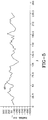
- Fig 6 shows a graph of the frequency spectrum 52 of the first derivative of the waveform.
- the first derivative frequency spectrum 52 enhances tire anomalies such as tread splices, ply splices, mold non-uniformities, mold runout, and tread pattern effects that are difficult to distinguish in the frequency spectrum of the waveform (see Fig 4).
- the radial and lateral forces of the tire 16 and the derivatives of the waveforms 30 may be represented in terms of maximum rates of change to compare the greatest tire force fluctuations to original equipment specifications.
- the derivatives may also be represented in terms of root mean squares to compare the tire specifications to original equipment specifications.
Landscapes
- Physics & Mathematics (AREA)
- General Physics & Mathematics (AREA)
- Testing Of Balance (AREA)
- Force Measurement Appropriate To Specific Purposes (AREA)
- Tires In General (AREA)
Abstract
The tyre uniformity analysis involves first measuring radial forces of a tire. A radial waveform is generated from measurements of the radial forces of the tyre. A first derivative of the radial waveform is calculated to obtain rate of change data between consecutive measurements of radial forces, preferably using a point-to-point slope calculation. The rate of change data of radial forces is compared to predetermined specifications. The derivatives may be represented in terms of peak-to-peak pounds force per square seconds, in terms of frequency spectrum, maximum rate of change, or in terms of root mean squares. Tyres not falling within the specifications are then removed.
Description
- This invention pertains generally to the art of methods and apparatuses for measuring and analyzing uniformity characteristics of tires, and more specifically to the measurement and analysis of radial and lateral forces using the waveforms of the forces and the first and second derivatives of those waveforms.
- 2. Conventional uniformity machine measurements and calculations depict the tire uniformity characteristics in terms of peak-to-peak amplitudes and spectral components for radial, lateral, and tangential forces. Plysteer, conicity, bulge, and valley radial and lateral runouts are also included.
- 3. Production tires are screened by uniformity machines, and the measured and calculated information is then compared to original equipment manufacturer's (OEM) specifications for a pass or fail sorting.
- 4. Ride testing indicates that its possible for tires to pass all OEM specifications and still cause rough ride and other undesirable vehicle effects.
- 5. The peak-to-peak amplitude of the above-mentioned parameters is important, but the rate of change of these parameters is also important. The rate of change of these parameters may be defined by the first and second derivatives with respect to time of these measured parameters.
- 6. Peak-to-peak variations may be within specifications, but the rate of change of these parameters can be very localized and cause instantaneous changes in velocity and acceleration. Today's sensitive automobile suspensions can pick up and transmit the localized changes through the vehicle. Additionally, while grinding of the offending tire may lower the peak-to-peak measurements of the above-mentioned parameters, grinding may not eliminate the high rates of change of the forces. In such case the tire may still produce an unacceptable ride.
- 7. US-A-Reissue 28 775 (TARPINIAN et al) discloses the use of force harmonics to mark tires.
- 8. US-A- 4 258 567 (FISHER, III) is directed to the use of force data to identify sidewall deformity in tires.
- 9. US-A- 5 313 827 (YOVICHIN) is directed to the use of runout measurements to identify sidewall deformity in tires.
- 10. US-A-3 894 421 (SPERBERG) and US-A-4 938 056 (DeRUDDER et al) disclose the measurement of pneumatic pressure in tires to detect uniformity problems.
- 11. The present invention contemplates a new and improved method for analyzing tire uniformity which is simple in design, effective in use, and overcomes the foregoing difficulties and others while providing better and more advantageous overall results.
- In accordance with the present invention, a new and improved method of analyzing the uniformity of tires is provided which utilizes the first and second derivatives of the radial and lateral force waveforms.
- 13. More particularly, in accordance with the present invention, a method for analyzing tire uniformity including a force machine, the method including the steps of measuring radial forces of a tire and measuring lateral forces of a tire. The method further includes the steps of creating a radial waveform from measurements of the radial forces of the tire, creating a lateral waveform from measurements of the lateral forces of the tire, calculating a first derivative of the radial waveform, calculating a first derivative of the lateral waveform, calculating a second derivative of the radial waveform, and calculating a second derivative of the lateral waveform.
- 14. According to one aspect of the present invention, the derivatives are calculated using a point-to-point slope calculation.
- 15. According to another aspect of the invention, the method further includes the steps of comparing the first derivative of the radial waveform to predetermined specifications, comparing the second derivative of the radial waveform to predetermined specifications, comparing the first derivative of the lateral waveform to predetermined specifications, and comparing the second derivative of the lateral waveform to predetermined specifications.
- 16. One advantage of the present invention is the ability to analyze and recognize tire non-uniformity that is undetected by peak-to-peak force calculations.
- 17. Another advantage of the present invention is the ability to recognize tires that can yield an unacceptable ride despite being within uniformity peak-to-peak force specifications.
- 18. Another advantage of the present invention is the ability to use existing force machines with only minor modifications in data analysis.
- 19. Another advantage of the present invention is to expose tire abnormalities such as tread splices, ply splices, mold non-uniformities, mold runout, and tread pattern effects that are of indistinguishable in force data sets.
- 20. Still other benefits and advantages of the invention will become apparent to those skilled in the art upon a reading and understanding of the following detailed specification.
- The invention may take physical form in certain parts and arrangement of parts. A preferred embodiment of these parts will be described in detail in the specification and illustrated in the accompanying drawings, which form a part of this disclosure and wherein:
- 22. Fig 1 shows a schematic representation of a tire force machine;
- Fig 2 shows a graph of a typical tire force variation of a tire;
- Fig 3 shows a graph of a typical tire force variation through one revolution of the tire referred to in Fig 2;
- Fig 4 shows a graph of the force variation frequency spectrum of the tire referred to in Fig 2;
- Fig 5 shows a graph of the first derivative of the force variation waveform of the tire referred to in Fig 2; and,
- Fig 6 shows a graph of the first derivative frequency spectrum of the tire referred to in Fig 2.
- Referring now to the drawings, which are for purposes of illustrating a preferred embodiment of the invention only, and not for purposes of limiting the invention, Fig 1 shows a schematic of a
force machine 10 used to measure the lateral and radial forces generated by tire non-uniformity. Aload wheel 14 applies a load to thetire 16 that is rotated by adrive wheel 18.Gauges 22 measure the lateral, tangential, and radial forces exerted by thetire 16. Lateral forces occur perpendicular to the plane in which thetire 16 rotates. Tangential forces act tangentially to the tire's footprint. Radial forces act parallel to a radius of thetire 16. The measurements are made electronically by theforce machine 10 in volts and converted to a force measurement by the following equation, herein known as "Equation 1":
force machine 10, and "forcei" is the force measurement converted to pounds. Uniformity data is then preferably transferred to acomputer 26 for analysis. - 24. Fig 2 shows a graph of a
waveform 30 of a radial force variation as measured by a force machine. Graphs of lateral force variations or tangential force variations (not shown) are derived in the same manner as the graphs of the radial force variations and are therefore not illustrated here to avoid the redundancy. The peak-to-peak, or amplitude "A" of the waveform is the difference of the maximum and minimum forces in one revolution of thewaveform 30. On the graph, thex-axis 32 denotes "time" and the y-axis 34 denotes "radial force". - 25. Fig 3 shows an expanded view of the
waveform 30 of one revolution of a tire. The amplitude of the waveform is shown by the measurement A. - 26. Fig 4 shows a
frequency spectrum graph 38, which reveals the harmonics of the tire. The frequency content of the radial force is calculated by measuring the number of force measurements recorded per rotation. A force variation that occurs once per rotation of the tire is denoted the "first harmonic." Similarly, a force variation that occurs twice per revolution of the tire is denoted the "second harmonic," and so on. Thefrequency spectrum graph 38 shows a first harmonic 40, third harmonic 42, and a fifth harmonic 44 on the particular tire (not shown) in the example. - 27. Fig 5 shows the graph of the
first derivative 48 of the waveform. The first derivative is calculated by a point-to-point method using the following equation, herein known as "Equation 2":
Equation 3":
- 28. Existing force machines may be used to make the measurements required for uniformity analysis, with only minor changes required for the gathering and analysis of the data. Such changes would include providing for the calculation and graphing of the first and second derivatives. Once tire non-uniformity is detected, or the derivatives of the particular force variation in question are found to be outside the range of the original equipment specifications, the offending tire may then be pulled from the production line. Tires which are outside of the specification range may be ground for the non-uniformity. Changes in the production process may then be implemented to correct the non-uniformities.
- 29. Fig 6 shows a graph of the
frequency spectrum 52 of the first derivative of the waveform. The firstderivative frequency spectrum 52 enhances tire anomalies such as tread splices, ply splices, mold non-uniformities, mold runout, and tread pattern effects that are difficult to distinguish in the frequency spectrum of the waveform (see Fig 4). - 30. The radial and lateral forces of the
tire 16 and the derivatives of thewaveforms 30 may be represented in terms of maximum rates of change to compare the greatest tire force fluctuations to original equipment specifications. The derivatives may also be represented in terms of root mean squares to compare the tire specifications to original equipment specifications. - 31. The invention has been described with reference to the preferred embodiment. Obviously, modifications and alterations will occur to others upon a reading and understanding of the specification. It is intended by applicant to include all such modifications and alterations insofar as they come within the scope of the appended claims.
Claims (10)
- A method for analyzing tire uniformity using a force machine (10), said method characterized by the steps of:measuring radial forces of a tire (16);generating a radial waveform from measurements of the radial forces of the tire;calculating a first derivative of the radial waveform to obtain rate of change data between consecutive measurements of radial forces;comparing the rate of change data of radial forces;calculating a second derivative of the radial waveform to obtain data about the first derivative of the radial waveform; and,comparing the data about the first derivative of the radial waveform to predetermined specifications.
- The method of claim 1 further comprising the steps of:measuring lateral forces of the tire;generating a lateral waveform from measurements of the lateral forces of the tire;calculating a first derivative of the lateral waveform to obtain rate of change data between consecutive measurements of lateral forces;comparing the rate of change data of lateral forces to predetermined specifications;calculating a second derivative of the lateral waveform to obtain data about the first derivative of the lateral waveform; and,comparing the data about the first derivative of the lateral waveform to predetermined specifications.
- The method of claim 2 wherein the radial and lateral waveforms are represented as force-time functions, and wherein the method further comprises the steps of:representing the first derivative of the radial waveform in terms of pounds force per seconds (N/s);representing the second derivative of the radial waveform in terms of pounds force per square seconds (N/s2);representing the first derivative of the lateral waveform in terms of pounds force per seconds (N/s); and,representing the second derivative of the lateral waveform in terms of pounds force per square seconds (N/s2).
- The method of Claim 1 further comprising the steps of:determining a root mean square of the rate of change data; andcomparing the root mean square with predetermined specifications.
- The method of claim 1 further comprising the steps of:measuring tangential forces of the tire;generating a tangential waveform from measurements of the tangential forces of the tire;calculating a first derivative of the tangential waveform to obtain rate of change data between consecutive measurements of tangential forces;calculating a second derivative of the tangential waveform to obtain data about the first derivative of the tangential waveform;comparing the rate of change data of tangential forces to predetermined specifications;comparing the data about the first derivative of the tangential waveform to predetermined specifications;removing the tire from sale when the first derivative of the tangential waveform does not fall within said predetermined specifications; and,removing the tire from sale when the second derivative of the tangential waveform does not fall within said predetermined specifications.
- A method for analyzing tire uniformity using a force machine (10), said method characterized by the steps of:measuring lateral forces of the tire (16);generating a lateral waveform from measurements of the lateral forces of the tire;calculating a first derivative of the lateral waveform to obtain rate of change data between consecutive measurements of the lateral forces;comparing the rate of change data of lateral forces to predetermined specifications;calculating a second derivative of the lateral waveform to obtain data about the first derivative; and,comparing the data about the first derivative to predetermined specifications.
- The method of claim 6 further comprising the steps of:measuring radial forces of the tire;generating a radial waveform from measurements of the radial forces of the tire;calculating a first derivative of the radial waveform to obtain rate of change data between consecutive measurements of the radial forces;calculating a second derivative of the radial waveform to obtain data about the first derivative of the radial waveform.comparing the rate of change data of the radial waveform to predetermined specifications;comparing the data about the first derivative of the radial waveform to predetermined specifications;removing the tire from sale when the first derivative of the radial waveform does not fall within said predetermined specifications; andremoving the tire from sale when the second derivative of the radial waveform does not fall within said predetermined specifications.
- The method of claim 6 further comprising the steps of:measuring tangential forces of the tire;generating a tangential waveform from measurements of the tangential forces of the tire;calculating a first derivative of the tangential waveform to obtain rate of change data between consecutive measurements of the tangential forces;calculating a second derivative of the tangential waveform to obtain data about the first derivative of the tangential waveform;comparing the rate of change data of the tangential waveform to predetermined specifications;comparing the data about the first derivative of the tangential waveform to predetermined specifications;removing the tire from sale when the first derivative of the tangential waveform does not fall within said predetermined specifications; andremoving the tire from sale when the second derivative of the tangential waveform does not fall within said predetermined specifications.
- The method of claim 8 wherein the lateral and tangential waveforms are represented as force-time functions, and wherein the method further comprises the steps of:determining the maximum value of the first derivative of the lateral waveform in terms of pounds force per seconds (N/s);determining the maximum value of the second derivative of the lateral waveform in terms of pounds force per square seconds (N/s2);determining the maximum value of the first derivative of the tangential waveform in terms of pounds force per seconds (N/s); and,determining the maximum value of the second derivative of the tangential waveform in terms of pounds force per square seconds (N/s2).
- The method of claim 9 wherein the lateral and tangential waveforms are represented as frequency spectrums.
Applications Claiming Priority (2)
| Application Number | Priority Date | Filing Date | Title |
|---|---|---|---|
| US08/611,916 US5639962A (en) | 1996-03-06 | 1996-03-06 | Enhanced tire uniformity machine data utilizing first and second derivative calculations |
| US611916 | 1996-03-06 |
Publications (2)
| Publication Number | Publication Date |
|---|---|
| EP0794419A2 true EP0794419A2 (en) | 1997-09-10 |
| EP0794419A3 EP0794419A3 (en) | 1998-11-04 |
Family
ID=24450921
Family Applications (1)
| Application Number | Title | Priority Date | Filing Date |
|---|---|---|---|
| EP97103113A Withdrawn EP0794419A3 (en) | 1996-03-06 | 1997-02-26 | Method for analyzing tire uniformity utilizing first and second derivative calculation |
Country Status (4)
| Country | Link |
|---|---|
| US (1) | US5639962A (en) |
| EP (1) | EP0794419A3 (en) |
| JP (1) | JPH09329510A (en) |
| CA (1) | CA2176413A1 (en) |
Cited By (3)
| Publication number | Priority date | Publication date | Assignee | Title |
|---|---|---|---|---|
| DE19942695C2 (en) * | 1998-10-14 | 2003-07-03 | Toyo Tire & Rubber Co | Method for changing the uniformity of a tire |
| WO2014105409A1 (en) * | 2012-12-28 | 2014-07-03 | Bridgestone Americas Tire Operations, Llc | Scalable vehicle models for indoor tire testing |
| US9428018B2 (en) | 2012-12-28 | 2016-08-30 | Bridgestone Americas Tire Operations, Llc | Scalable vehicle models for indoor tire testing |
Families Citing this family (17)
| Publication number | Priority date | Publication date | Assignee | Title |
|---|---|---|---|---|
| US5845232A (en) * | 1996-05-10 | 1998-12-01 | Measurement Systems, Incorporated | Apparatus and method for detecting splice overlaps or splice gaps in a tire |
| US6826951B1 (en) | 1998-01-15 | 2004-12-07 | International Marketing, Inc. | Tire management system and method for surveying and servicing a vehicle tire |
| DE19909162A1 (en) | 1999-03-03 | 2000-09-07 | Schenck Rotec Gmbh | Method for reducing vibrations caused by a wheel unit of a vehicle and device therefor |
| US6673184B1 (en) | 2000-02-23 | 2004-01-06 | The Goodyear Tire & Rubber Company | Tire and method for correcting tire uniformity thereof |
| US6651716B1 (en) | 2000-02-23 | 2003-11-25 | The Goodyear Tire & Rubber Company | Method and tire adapted for post cure tire uniformity correction |
| US6257956B1 (en) | 2000-03-06 | 2001-07-10 | The Goodyear Tire & Rubber Company | Method to identify and remove machine contributions from tire uniformity measurements |
| US6740280B1 (en) | 2000-04-10 | 2004-05-25 | The Goodyear Tire & Rubber Company | Tire construction method for improving tire uniformity |
| DE10062251C2 (en) * | 2000-12-14 | 2002-12-12 | Fraunhofer Ges Forschung | Device and method for checking the quality of a body |
| US7228732B2 (en) * | 2001-01-26 | 2007-06-12 | Bridgestone Firestone North American Tire, Llc | Tire wear analysis method |
| US6532811B2 (en) | 2001-01-26 | 2003-03-18 | Bridgestone/Firestone North American Tire, Llc | Method of wear testing a tire |
| US20090260743A1 (en) * | 2003-11-21 | 2009-10-22 | William David Mawby | Tire manufacturing method for improving the uniformity of a tire |
| US7328114B2 (en) * | 2005-12-09 | 2008-02-05 | General Electric Company | Methods and systems for measuring a rate of change of frequency |
| DE102007001837B4 (en) * | 2007-01-12 | 2010-12-09 | Ford Global Technologies, LLC, Dearborn | Method and device for determining fluctuations of tangential forces on a tire of a motor vehicle and motor vehicle |
| WO2009041980A1 (en) * | 2007-09-28 | 2009-04-02 | Societe De Technologie Michelin | Correction of crown layer variance during retreading |
| WO2015069272A1 (en) | 2013-11-08 | 2015-05-14 | Compagnie Generale Des Etablissements Michelin | Tire uniformity improvement through modified sampling of uniformity parameters |
| US9677972B2 (en) * | 2015-10-26 | 2017-06-13 | Commercial Time Sharing Inc. | System and method for characterizing tire uniformity machines |
| CN115684737B (en) * | 2022-10-26 | 2023-11-17 | 常州同惠电子股份有限公司 | Algorithm for calculating waveform glitch |
Family Cites Families (22)
| Publication number | Priority date | Publication date | Assignee | Title |
|---|---|---|---|---|
| US3722270A (en) * | 1965-10-24 | 1973-03-27 | L Sperberg | Non-destructive method of determining tire life |
| US3563088A (en) * | 1966-09-12 | 1971-02-16 | Lawrence R Sperberg | Non-destructive method of determining tire life |
| US3478581A (en) * | 1967-01-10 | 1969-11-18 | Lawrence R Sperberg | Apparatus for measuring tire uniformity |
| US3577780A (en) * | 1967-01-10 | 1971-05-04 | Lawrence R Sperberg | Method of measuring tire uniformity |
| USRE28775E (en) * | 1967-06-09 | 1976-04-20 | Uniroyal Inc. | Harmonic signal analyzer system for testing tires |
| US3500681A (en) * | 1968-08-12 | 1970-03-17 | Goodrich Co B F | Locating maximum radial force variation in a tire |
| US3550442A (en) * | 1968-09-05 | 1970-12-29 | Uniroyal Inc | Method and apparatus for measuring uniformity of tires |
| DE2326046C2 (en) * | 1973-05-22 | 1974-08-29 | Gebr. Hofmann Kg Maschinenfabrik, 6100 Darmstadt | Method and device for checking the quality of tires, in particular motor vehicle tires |
| US3894421A (en) * | 1973-08-17 | 1975-07-15 | Lawrence R Sperberg | Method of measuring tire dynamic strength |
| US3919882A (en) * | 1974-02-11 | 1975-11-18 | Donald R Wells | Tire inspection apparatus and method |
| US4241300A (en) * | 1977-03-24 | 1980-12-23 | Eagle-Picher Industries, Inc. | Circuit responsive to rate change in amplitude of analog electrical signal for use in tire processing apparatus |
| US4258567A (en) * | 1979-09-27 | 1981-03-31 | The Firestone Tire & Rubber Company | Tire sidewall deformity tester and method |
| JPS56122931A (en) * | 1980-03-03 | 1981-09-26 | Bridgestone Corp | Method and device for checking tire |
| US4404848A (en) * | 1981-02-26 | 1983-09-20 | Kabushiki Kaisha Kobe Seiko Sho | Method for correcting measurement errors in tire uniformity inspecting machines |
| US4402218A (en) * | 1981-06-03 | 1983-09-06 | The Goodyear Tire & Rubber Company | Method and apparatus for sidewall bulge and valley detection |
| US4422336A (en) * | 1981-12-02 | 1983-12-27 | Eagle-Picher Industries, Inc. | Instrumentation resonance compensation |
| KR960000995B1 (en) * | 1987-06-12 | 1996-01-15 | 이글 피쳐 인더스트리즈 인코포레이티드 | Apparatus and the method for improving uniformity measurement |
| US4938056A (en) * | 1989-05-30 | 1990-07-03 | The Uniroyal Goodrich Tire Company | Determining the air permeability of a tire |
| DE4200997C2 (en) * | 1992-01-16 | 1994-02-03 | Steyr Daimler Puch Ag | Method for determining the driving dynamics safety reserve of motor vehicles |
| US5313827A (en) * | 1992-09-28 | 1994-05-24 | The Goodyear Tire & Rubber Company | Method and apparatus for detecting ply defects in pneumatic tires |
| DE4238118C2 (en) * | 1992-11-12 | 2002-12-05 | Hofmann Maschinen Und Anlagenbau Gmbh | Method for measuring tire irregularities |
| DE4335938A1 (en) * | 1992-12-17 | 1995-04-27 | Continental Ag | Aquaplaning detection method for vehicle tires |
-
1996
- 1996-03-06 US US08/611,916 patent/US5639962A/en not_active Expired - Fee Related
- 1996-05-13 CA CA002176413A patent/CA2176413A1/en not_active Abandoned
-
1997
- 1997-02-26 EP EP97103113A patent/EP0794419A3/en not_active Withdrawn
- 1997-02-27 JP JP9043690A patent/JPH09329510A/en active Pending
Cited By (3)
| Publication number | Priority date | Publication date | Assignee | Title |
|---|---|---|---|---|
| DE19942695C2 (en) * | 1998-10-14 | 2003-07-03 | Toyo Tire & Rubber Co | Method for changing the uniformity of a tire |
| WO2014105409A1 (en) * | 2012-12-28 | 2014-07-03 | Bridgestone Americas Tire Operations, Llc | Scalable vehicle models for indoor tire testing |
| US9428018B2 (en) | 2012-12-28 | 2016-08-30 | Bridgestone Americas Tire Operations, Llc | Scalable vehicle models for indoor tire testing |
Also Published As
| Publication number | Publication date |
|---|---|
| JPH09329510A (en) | 1997-12-22 |
| US5639962A (en) | 1997-06-17 |
| CA2176413A1 (en) | 1997-09-07 |
| EP0794419A3 (en) | 1998-11-04 |
Similar Documents
| Publication | Publication Date | Title |
|---|---|---|
| EP0794419A2 (en) | Method for analyzing tire uniformity utilizing first and second derivative calculation | |
| EP2837510B1 (en) | Torsional mode tire wear state estimation system and method | |
| US4311044A (en) | Tire sidewall bump/depression detection system | |
| US5396438A (en) | Tire manufacturing method | |
| EP2012106B1 (en) | Deflection calculating method at tire wheeling time, data storing method at tire wheeling time, and grounding length calculating method at tire wheeling time | |
| US6139401A (en) | Method of correcting the imbalance of a pneumatic tire with a tire uniformity machine | |
| US5027649A (en) | Process and apparatus for testing the uniformity of pneumatic tires | |
| CN106872186B (en) | System and method for characterizing a tire uniformity testing machine | |
| JPH1010015A (en) | Mechanical vibration analyzing method of tire homogeneous machine | |
| CN103245516A (en) | System for characterizing tire uniformity machines and methods of using the characterizations | |
| US6705156B2 (en) | Cross-correlation method for identification and removal of machine contribution from tire uniformity measurements | |
| CN112345273B (en) | Tire high-speed uniformity equipment controlled tire monitoring method | |
| EP0599465B1 (en) | Method of correcting radial force variations and lateral force variations in a pneumatic tire | |
| US20110257902A1 (en) | Method and system for determining the potential friction between a vehicle tyre and a rolling surface | |
| US5845232A (en) | Apparatus and method for detecting splice overlaps or splice gaps in a tire | |
| CN114940037A (en) | Safe measurement of tire characteristics | |
| US4702103A (en) | Method of quality grading in uniformity tests of rotors, in particular of automobile tires | |
| EP2827121B1 (en) | System for characterizing tire uniformity machines and methods of using the characterizations | |
| EP4010678B1 (en) | Method of testing a tyre | |
| EP1429134B1 (en) | Method and device for testing the uniformity of a tyre | |
| EP3835090B1 (en) | Tire type distinguishing method and tire type distinguishing device | |
| WO1998008070A1 (en) | Method of balance screening a pneumatic tire with a tire uniformity machine | |
| CN118776925B (en) | Method, equipment and computer program product for testing indoor impact of automobile tire | |
| WO1998016810A1 (en) | Method of correcting the imbalance of a pneumatic tire with a tire uniformity machine | |
| JP2003312219A (en) | Tire and tire abnormality detecting device using the tire |
Legal Events
| Date | Code | Title | Description |
|---|---|---|---|
| PUAI | Public reference made under article 153(3) epc to a published international application that has entered the european phase |
Free format text: ORIGINAL CODE: 0009012 |
|
| 17P | Request for examination filed |
Effective date: 19970226 |
|
| AK | Designated contracting states |
Kind code of ref document: A2 Designated state(s): DE FR GB |
|
| PUAL | Search report despatched |
Free format text: ORIGINAL CODE: 0009013 |
|
| AK | Designated contracting states |
Kind code of ref document: A3 Designated state(s): DE FR GB |
|
| STAA | Information on the status of an ep patent application or granted ep patent |
Free format text: STATUS: THE APPLICATION HAS BEEN WITHDRAWN |
|
| 18W | Application withdrawn |
Withdrawal date: 20001017 |