EP0794349B1 - Disc brake caliper assembly - Google Patents
Disc brake caliper assembly Download PDFInfo
- Publication number
- EP0794349B1 EP0794349B1 EP97301500A EP97301500A EP0794349B1 EP 0794349 B1 EP0794349 B1 EP 0794349B1 EP 97301500 A EP97301500 A EP 97301500A EP 97301500 A EP97301500 A EP 97301500A EP 0794349 B1 EP0794349 B1 EP 0794349B1
- Authority
- EP
- European Patent Office
- Prior art keywords
- brake
- disc
- pads
- caliper assembly
- pad
- Prior art date
- Legal status (The legal status is an assumption and is not a legal conclusion. Google has not performed a legal analysis and makes no representation as to the accuracy of the status listed.)
- Expired - Lifetime
Links
- 239000002184 metal Substances 0.000 claims description 4
- 230000002159 abnormal effect Effects 0.000 description 1
- 230000005484 gravity Effects 0.000 description 1
- 230000001939 inductive effect Effects 0.000 description 1
Images



Classifications
-
- F—MECHANICAL ENGINEERING; LIGHTING; HEATING; WEAPONS; BLASTING
- F16—ENGINEERING ELEMENTS AND UNITS; GENERAL MEASURES FOR PRODUCING AND MAINTAINING EFFECTIVE FUNCTIONING OF MACHINES OR INSTALLATIONS; THERMAL INSULATION IN GENERAL
- F16D—COUPLINGS FOR TRANSMITTING ROTATION; CLUTCHES; BRAKES
- F16D65/00—Parts or details
- F16D65/02—Braking members; Mounting thereof
- F16D65/04—Bands, shoes or pads; Pivots or supporting members therefor
- F16D65/092—Bands, shoes or pads; Pivots or supporting members therefor for axially-engaging brakes, e.g. disc brakes
- F16D65/095—Pivots or supporting members therefor
- F16D65/097—Resilient means interposed between pads and supporting members or other brake parts
- F16D65/0973—Resilient means interposed between pads and supporting members or other brake parts not subjected to brake forces
- F16D65/0974—Resilient means interposed between pads and supporting members or other brake parts not subjected to brake forces acting on or in the vicinity of the pad rim in a direction substantially transverse to the brake disc axis
- F16D65/0977—Springs made from sheet metal
-
- F—MECHANICAL ENGINEERING; LIGHTING; HEATING; WEAPONS; BLASTING
- F16—ENGINEERING ELEMENTS AND UNITS; GENERAL MEASURES FOR PRODUCING AND MAINTAINING EFFECTIVE FUNCTIONING OF MACHINES OR INSTALLATIONS; THERMAL INSULATION IN GENERAL
- F16D—COUPLINGS FOR TRANSMITTING ROTATION; CLUTCHES; BRAKES
- F16D55/00—Brakes with substantially-radial braking surfaces pressed together in axial direction, e.g. disc brakes
- F16D55/02—Brakes with substantially-radial braking surfaces pressed together in axial direction, e.g. disc brakes with axially-movable discs or pads pressed against axially-located rotating members
- F16D55/22—Brakes with substantially-radial braking surfaces pressed together in axial direction, e.g. disc brakes with axially-movable discs or pads pressed against axially-located rotating members by clamping an axially-located rotating disc between movable braking members, e.g. movable brake discs or brake pads
- F16D55/228—Brakes with substantially-radial braking surfaces pressed together in axial direction, e.g. disc brakes with axially-movable discs or pads pressed against axially-located rotating members by clamping an axially-located rotating disc between movable braking members, e.g. movable brake discs or brake pads with a separate actuating member for each side
-
- F—MECHANICAL ENGINEERING; LIGHTING; HEATING; WEAPONS; BLASTING
- F16—ENGINEERING ELEMENTS AND UNITS; GENERAL MEASURES FOR PRODUCING AND MAINTAINING EFFECTIVE FUNCTIONING OF MACHINES OR INSTALLATIONS; THERMAL INSULATION IN GENERAL
- F16D—COUPLINGS FOR TRANSMITTING ROTATION; CLUTCHES; BRAKES
- F16D55/00—Brakes with substantially-radial braking surfaces pressed together in axial direction, e.g. disc brakes
- F16D2055/0004—Parts or details of disc brakes
- F16D2055/007—Pins holding the braking members
Definitions
- the present invention relates to a disc brake caliper assembly for use with a brake disc and, more particularly, to a disc brake caliper assembly including a single pad-supporting pin for supporting first and second opposed pads radially outwardly of the brake disc and a spring member for moving the pads away from the brake disc upon brake release.
- Japanese Utility Model Application laid-open No. Hei 5-45266 discloses a disc brake caliper assembly for use with a brake disc.
- the disc brake caliper assembly includes first and second opposed pads positioned on opposite sides of the brake disc and movable towards and away from the brake disc; a stationary member for receiving a braking torque from the pads during braking, and a single pad-supporting pin located centrally in a radial plane which bisects the pads.
- the disc brake caliper assembly further includes a pair of spring members for moving the pads away from the brake disc upon brake release. Each of the spring members is located at a position offset from the central supporting pin.
- the provision of a pair of spring members increases the cost of the disc brake caliper assembly. If one of the spring members were omitted to reduce the cost of the disc brake caliper assembly, a portion of each pad on the side of the central pin remote from the spring could remain in engagement with the brake disc on brake release thereby increasing the drag braking torque and creating abnormal wear on the pads.
- US 3841444 discloses a disc brake with a radially open caliper and having an anti-rattle spring for holding down a pair of friction pads.
- the spring is made of wire and rests against the upper sides of the friction pads and against at least one retaining pin held in the caliper for retaining the pads.
- a disc brake caliper assembly for use with a brake disc comprising
- the disc brake caliper assembly 10 for use with a brake disc.
- the disc brake caliper assembly 10 includes first and second opposed pads 12 and 13 for mounting on opposite sides of the brake disc 11 and being movable towards and away from the brake disc 11, and a stationary member 14 for receiving a braking torque from the pads 12 and 13 upon a braking operation.
- the stationary member 14 is provided with first and second cylinders 15 and 16 into which first and second pistons 17 and 18 are inserted to define first and second braking pressure chambers 19 and 20 in the cylinders 15 and 16 respectively.
- the pistons 17 and 18 are moved by braking pressures supplied to the braking pressure chambers 19 and 20, and the pads 12 and 13 are moved against the brake disc 11 by the pistons 17 and 18 respectively for applying a braking torque to the brake disc 11.
- a single pad-supporting pin 21 and first and second reaction faces 22 and 23 are provided on the stationary member 14.
- the pad-supporting pin 21 is offset relative to a radial centre-line through the pads 12 and 13 in the normal forward rotating direction of the brake disc 11 as shown by an arrow in Figure 2. That direction of offset is referred to in this Specification as the forward direction.
- Both ends of the pad-supporting pin 21 are supported by being inserted into holes provided in the stationary member 14, and the pad-supporting pin 21 movably penetrates and slidingly supports a backing plate 24 of the pad 12 and a backing plate 25 of the pad 13.
- the first reaction face 22 absorbs braking reaction torque from a forwardly facing edge of the backing plate 24 of the pad 12 to prevent the pad 12 from undergoing pivotal movement about the pad-supporting pin 21, and associated radially inwardly directed movement of the said forwardly facing edge of the backing plate 24, during braking.
- the second reaction face 23 similarly absorbs braking reaction torque from a forwardly facing edge of the backing plate 25 of the pad 13.
- a spring member 26 For axially biasing the pads 12 and 13 apart and away from the brake disc 11 there is provided a spring member 26 made of sheet metal.
- the spring member 26 has a flexible spine portion 27 which lies above and between the pads 12 and 13, over an outer periphery of the brake disc 11.
- a curved locating portion 27b of the spine portion 27 passes beneath the pad-supporting pin 21 and is received in a recess 21a in the form of annular groove formed on a middle portion of the pad-supporting pin 21.
- Extending forwardly from the curved locating portion 27b of the spine portion 27 is a relatively short tail portion 27c which in use resiliently abuts a radially outwardly directed reaction face 14a of the stationary member 14.
- the rearwardly extending part of the spine portion 27 extends as far as a radial plane which bisects the pads, where at 27a it terminates in a pair of resilient transverse arms 28,29.
- Each resilient transverse arm 28 or 29 comprises a laterally extending portion 28a or 29a extending outwardly above, and over a centre plane, of the associated brake pad 12 or 13, and a return portion extending from a distal end portion of the laterally extending portion inwardly and downwardly so as to contact the backing plate 24 or 25 of the associated pad 12 or 13, and to bias the associated pad away from the brake disc 11 on brake release.
- Each resilient transverse arm 28 or 29 thus comprises a first portion, being the laterally extending portion 28a or 29a; a third portion, being the return portion 28c or 29c; and a second portion, being a preferably curved joining piece 28b or 29b resiliently connecting together the first and third portions.
- Each third portion 28c or 29c extends obliquely across the edge of a shallow recess 24a or 25a formed in the upper edge of the backing plate 24 or 25 of the associated brake pad 12 or 13, to apply an axial biasing force F1 and a radial biasing force F2 on the associated pad 12 or 13 as illustrated in Figure 4 with reference to pad 12.
- the force F1 separates the pads from the brake disc on brake release and the force F2 prevents rattle of the pads in use.
- the spring member 26 also limits the sliding movement of the pad-supporting pin 21 relative to the stationary member 14.
- a shim member 30 is interposed between the backing plate 24 of the first pad 12 and the piston 17, and a shim member 31 is interposed between the backing plate 25 of the second pad 13 and the piston 17.
- the shim members 30 and 31 have apertures through which the pad-supporting pin 21 passes.
- FIG 5 there is shown a spring member 32 which may be used in a second embodiment, in place of the spring member 26 and the pad-supporting pin 21 described above.
- the spring member 32 incorporates an integral pad-supporting pin 33 to replace the pad-supporting pin 21 shown in Figures 1 to 4.
- the spring member 32 and its integral pad-supporting pin 33 are made of sheet metal and formed as one piece.
- a second embodiment of the invention, incorporating the spring member 32 and integral pin 33, is otherwise precisely as described above with reference to the first embodiment.
Landscapes
- Engineering & Computer Science (AREA)
- General Engineering & Computer Science (AREA)
- Mechanical Engineering (AREA)
- Braking Arrangements (AREA)
Description
- The present invention relates to a disc brake caliper assembly for use with a brake disc and, more particularly, to a disc brake caliper assembly including a single pad-supporting pin for supporting first and second opposed pads radially outwardly of the brake disc and a spring member for moving the pads away from the brake disc upon brake release.
- Japanese Utility Model Application laid-open No. Hei 5-45266 discloses a disc brake caliper assembly for use with a brake disc. The disc brake caliper assembly includes first and second opposed pads positioned on opposite sides of the brake disc and movable towards and away from the brake disc; a stationary member for receiving a braking torque from the pads during braking, and a single pad-supporting pin located centrally in a radial plane which bisects the pads. The disc brake caliper assembly further includes a pair of spring members for moving the pads away from the brake disc upon brake release. Each of the spring members is located at a position offset from the central supporting pin.
- For moving the pads away from the brake disc upon brake release, the provision of a pair of spring members increases the cost of the disc brake caliper assembly. If one of the spring members were omitted to reduce the cost of the disc brake caliper assembly, a portion of each pad on the side of the central pin remote from the spring could remain in engagement with the brake disc on brake release thereby increasing the drag braking torque and creating abnormal wear on the pads.
- US 3841444 discloses a disc brake with a radially open caliper and having an anti-rattle spring for holding down a pair of friction pads. The spring is made of wire and rests against the upper sides of the friction pads and against at least one retaining pin held in the caliper for retaining the pads.
- It is an object of this invention to reduce both the drag braking torque and the cost.
- To achieve the above-stated object, according to the present invention there is provided a disc brake caliper assembly for use with a brake disc comprising
- first and second opposed brake pads carried by a single pad-supporting pin for mounting on opposite sides of the brake disc for transferring braking torque from the brake disc to a stationary member of the caliper assembly,
- a single spring for separating the pads on brake release in use, the spring comprising
- a forwardly extending tail portion for abutting a stationary radially outwardly directed reaction face of the caliper assembly; and
- a rearwardly extending resilient spine portion having at a rear end a pair of resilient transversely extending arms contacting central portions of the pair of pads to bias the pads away from the brake disc on brake release;
- wherein the pad-supporting pin is offset, in the direction of disc rotation, from a radial centre plane through the pads; and CHARACTERISED IN THAT the spring and the pad-supporting pin are formed in one piece.
-
-
- Figure 1 is a sectional view of an embodiment of a disc brake caliper assembly according to the invention;
- Figure 2 is a top view of the embodiment;
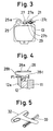
- Figure 3 is a view showing a relation among a pad, a pad-supporting pin and a spring member of an embodiment not in accordance with the invention;
- Figure 4 is a view showing a relation between a pad and the spring member of the embodiment;
- Figure 5 is a view showing a spring member and a pad-supporting pin of an embodiment of the invention; and
- Figure 6 is a side view of a friction pad illustrating the forces experienced during braking.
-
- Referring first to Figures 1 to 4, there is shown an embodiment of a disc
brake caliper assembly 10 of the invention for use with a brake disc. The discbrake caliper assembly 10 includes first and second opposedpads brake disc 11 and being movable towards and away from thebrake disc 11, and astationary member 14 for receiving a braking torque from thepads stationary member 14 is provided with first andsecond cylinders second pistons braking pressure chambers cylinders pistons braking pressure chambers pads brake disc 11 by thepistons brake disc 11. - For supporting the
pads brake disc 11, a single pad-supportingpin 21 and first and second reaction faces 22 and 23 are provided on thestationary member 14. The pad-supportingpin 21 is offset relative to a radial centre-line through thepads brake disc 11 as shown by an arrow in Figure 2. That direction of offset is referred to in this Specification as the forward direction. Both ends of the pad-supportingpin 21 are supported by being inserted into holes provided in thestationary member 14, and the pad-supportingpin 21 movably penetrates and slidingly supports abacking plate 24 of thepad 12 and abacking plate 25 of thepad 13. Thefirst reaction face 22 absorbs braking reaction torque from a forwardly facing edge of thebacking plate 24 of thepad 12 to prevent thepad 12 from undergoing pivotal movement about the pad-supportingpin 21, and associated radially inwardly directed movement of the said forwardly facing edge of thebacking plate 24, during braking. Thesecond reaction face 23 similarly absorbs braking reaction torque from a forwardly facing edge of thebacking plate 25 of thepad 13. - For axially biasing the
pads brake disc 11 there is provided aspring member 26 made of sheet metal. Thespring member 26 has aflexible spine portion 27 which lies above and between thepads brake disc 11. Acurved locating portion 27b of thespine portion 27 passes beneath the pad-supportingpin 21 and is received in arecess 21a in the form of annular groove formed on a middle portion of the pad-supportingpin 21. Extending forwardly from thecurved locating portion 27b of thespine portion 27 is a relativelyshort tail portion 27c which in use resiliently abuts a radially outwardly directed reaction face 14a of thestationary member 14. The rearwardly extending part of thespine portion 27 extends as far as a radial plane which bisects the pads, where at 27a it terminates in a pair of resilienttransverse arms - Each resilient
transverse arm portion 28a or 29a extending outwardly above, and over a centre plane, of the associatedbrake pad backing plate pad brake disc 11 on brake release. - Each resilient
transverse arm portion 28a or 29a; a third portion, being thereturn portion piece third portion shallow recess backing plate brake pad pad - The
spring member 26 also limits the sliding movement of the pad-supportingpin 21 relative to thestationary member 14. - As shown in Figures 1 and 2, a
shim member 30 is interposed between thebacking plate 24 of thefirst pad 12 and thepiston 17, and ashim member 31 is interposed between thebacking plate 25 of thesecond pad 13 and thepiston 17. Theshim members pin 21 passes. - In Figure 5, there is shown a
spring member 32 which may be used in a second embodiment, in place of thespring member 26 and the pad-supportingpin 21 described above. Thespring member 32 incorporates an integral pad-supportingpin 33 to replace the pad-supportingpin 21 shown in Figures 1 to 4. Thespring member 32 and its integral pad-supportingpin 33 are made of sheet metal and formed as one piece. A second embodiment of the invention, incorporating thespring member 32 andintegral pin 33, is otherwise precisely as described above with reference to the first embodiment. - From Figure 6 it will be seen that during braking a force F is exerted on the
pad 12 through its centre of gravity G. That provides a moment M inducing pivotal movement of thepad 12 about thepin 21. There is thus an associated bias on thepad 12 to urge the forwardly facing edge radially inwardly of the disc.
Claims (6)
- A disc brake caliper assembly (10) for use with a brake disc (11) comprising:CHARACTERISED IN THAT the spring (26,32) and the pad-supporting pin (21,33) are formed in one piece.first and second opposed brake pads (12,13) carried by a single pad-supporting pin (21,33) for mounting on opposite sides of the brake disc (11) for transferring braking torque from the brake disc to a stationary member (14) of the caliper assembly (10),a single spring (26,32) for separating the pads (12,13) on brake release in use, the spring (26,32) comprisinga forwardly extending tail portion (27c) for abutting a stationary radially outwardly directed reaction face of the caliper assembly; anda rearwardly extending resilient spine portion (27) having at a rear end (27a) a pair of resilient transversely extending arms (28,29) contacting central portions of the pair of pads (12,13) to bias the pads away from the brake disc (11) on brake release;wherein the pad-supporting pin (21,33) is offset, in the direction of disc rotation, from a radial centre plane through the pads (12,13); and
- A disc brake caliper assembly according to claim 1, wherein each of the pair of resilient transversely extending arms (28,29) comprises a laterally extending portion (28a,29a) extending laterally outwardly above, and over a central portion of, an associated one of the pair of brake pads, the transverse arms (28,29) terminating in a pair of folded-under return portions (28c,29c) connected to the distal ends of the laterally extending portions (28a,29a) by resilient joining portions (28b,29b), wherein the return portions (28c,29c) extend inwardly and downwardly from the joining portions (28b,29b) so as to contact the brake pads (12,13) to bias the pads away from the brake disc (11) on brake release.
- A disc brake caliper assembly according to claim 2, wherein the return portions (28c,29c) also bias the pads (12,13) radially inwardly of the disc (11).
- A disc brake caliper assembly according to claim 2 or claim 3, wherein the return portions (28c,29c) contact the brake pads (12,13) at recessed portions (24a,25a) formed in the upper edges of backing plates (24,25) of the brake pads (12,13).
- A disc brake caliper assembly according to any preceding claim, wherein the spring (26,32) is formed from sheet metal and the pad-supporting pin (26,33) is provided by forming lateral side extensions of the sheet metal into rolled pin ends coaxial with one another.
- A disc brake caliper assembly according to any preceding claim, further comprising first and second opposed cylinders (15,16) provided in a stationary member (14), and first and second pistons (17,18) received in the first and second cylinders (15,16) to define first and second braking pressure chambers (19,20) in the first and second cylinders (15,16) respectively, the first and second pistons (17,18) being movable by braking pressures supplied to the first and second braking pressure chambers (19,20) respectively to effect actuation of the first and second brake pads (12,13) against the brake disc (11).
Applications Claiming Priority (4)
| Application Number | Priority Date | Filing Date | Title |
|---|---|---|---|
| JP49105/96 | 1996-03-06 | ||
| JP4910596 | 1996-03-06 | ||
| JP4910596 | 1996-03-06 | ||
| US08/810,818 US5829555A (en) | 1996-03-06 | 1997-03-06 | Disc brake caliper assembly |
Publications (3)
| Publication Number | Publication Date |
|---|---|
| EP0794349A2 EP0794349A2 (en) | 1997-09-10 |
| EP0794349A3 EP0794349A3 (en) | 1998-01-28 |
| EP0794349B1 true EP0794349B1 (en) | 2001-06-13 |
Family
ID=26389461
Family Applications (1)
| Application Number | Title | Priority Date | Filing Date |
|---|---|---|---|
| EP97301500A Expired - Lifetime EP0794349B1 (en) | 1996-03-06 | 1997-03-06 | Disc brake caliper assembly |
Country Status (2)
| Country | Link |
|---|---|
| US (1) | US5829555A (en) |
| EP (1) | EP0794349B1 (en) |
Families Citing this family (11)
| Publication number | Priority date | Publication date | Assignee | Title |
|---|---|---|---|---|
| JP2004511738A (en) * | 2000-10-18 | 2004-04-15 | アケボノ・コーポレイション・ノース・アメリカ | Springs for pad retraction and retention in caliper-type disc brake assemblies |
| US6920965B2 (en) * | 2000-10-18 | 2005-07-26 | Continental Teves Ag & Co. Ohg | Spot-type disc brake with a spring assembly for a brake pad |
| JP4156516B2 (en) * | 2001-10-31 | 2008-09-24 | フレニ・ブレンボ エス・ピー・エー | Leaf spring for preloading disc brake pads |
| US7467693B2 (en) * | 2002-04-10 | 2008-12-23 | Akebono Corporation (North America) | Disc brake pad return spring |
| DE602006008047D1 (en) * | 2006-02-17 | 2009-09-03 | Freni Brembo Spa | SPRINGS FOR HOLDING BAKINGS IN A DISC BRAKE CALIPER |
| JP4732256B2 (en) * | 2006-06-26 | 2011-07-27 | 曙ブレーキ工業株式会社 | Disc brake pad clip |
| JP5454352B2 (en) * | 2010-05-20 | 2014-03-26 | 株式会社アドヴィックス | Disc brake device |
| ITPD20120398A1 (en) * | 2012-12-20 | 2014-06-21 | Freni Brembo Spa | BRAKE CALIPER WITH DISC |
| US9328785B2 (en) | 2013-03-15 | 2016-05-03 | Hb Performance Systems, Inc. | Tensioned brake pad |
| EP3175134B1 (en) * | 2014-08-01 | 2018-03-21 | Freni Brembo S.p.A. | Disc brake caliper employing a spring to influence pads acting on the disc of the disc brake |
| EP3023666B2 (en) * | 2014-11-20 | 2022-09-14 | Meritor Heavy Vehicle Braking Systems (UK) Limited | Disc brake assembly |
Family Cites Families (10)
| Publication number | Priority date | Publication date | Assignee | Title |
|---|---|---|---|---|
| DE1931752C3 (en) * | 1969-06-23 | 1982-12-02 | Alfred Teves Gmbh, 6000 Frankfurt | Brake shoe holder for partially lined disc brakes |
| US3783980A (en) * | 1971-10-13 | 1974-01-08 | Itt | Brake lining holding arrangement for spot-type disc brakes |
| FR2199828A5 (en) * | 1972-05-12 | 1974-04-12 | Bendix Gmbh | |
| DE2225178A1 (en) * | 1972-05-24 | 1974-01-17 | Teves Gmbh Alfred | PARTIAL DISC BRAKE |
| FR2425579A1 (en) * | 1978-05-11 | 1979-12-07 | Dba | DISC BRAKE AND NOISE SPRING FOR SUCH A BRAKE |
| JPS55105629U (en) * | 1979-01-19 | 1980-07-23 | ||
| AU6759981A (en) * | 1980-03-01 | 1981-09-10 | Lucas Industries Limited | Disc brakes and friction pad assemblies therefor |
| JPH07746Y2 (en) * | 1990-04-28 | 1995-01-11 | 日信工業株式会社 | Reaction force type disc brake |
| DE4115635A1 (en) * | 1991-05-14 | 1992-11-19 | Teves Gmbh Alfred | FLOATING SADDLE DISC BRAKE, ESPECIALLY FOR MOTOR VEHICLES |
| JPH0545266A (en) * | 1991-08-14 | 1993-02-23 | Canon Inc | Method for preparing specimen for interatom force microscope |
-
1997
- 1997-03-06 US US08/810,818 patent/US5829555A/en not_active Expired - Lifetime
- 1997-03-06 EP EP97301500A patent/EP0794349B1/en not_active Expired - Lifetime
Also Published As
| Publication number | Publication date |
|---|---|
| US5829555A (en) | 1998-11-03 |
| EP0794349A2 (en) | 1997-09-10 |
| EP0794349A3 (en) | 1998-01-28 |
Similar Documents
| Publication | Publication Date | Title |
|---|---|---|
| US5687817A (en) | Disc brake | |
| JP3863250B2 (en) | Disc brake | |
| US4279331A (en) | Floating-caliper disc brake | |
| US4364455A (en) | Retraction spring for disc brake pads | |
| JPH10184744A (en) | Disc brake | |
| US4467897A (en) | Disc brake with first and second springs for preventing the vibration of friction pad | |
| EP0794349A2 (en) | Disc brake caliper assembly | |
| US6971486B2 (en) | Caliper spring clip with axial force direction | |
| US6189659B1 (en) | Disk brake | |
| JPS6234968B2 (en) | ||
| JPH05240274A (en) | Disc brake | |
| EP0143170B1 (en) | Disc brake friction pad support and biasing assembly | |
| US6915882B2 (en) | Method and apparatus for constructing disc brakes | |
| JPH1054431A (en) | Disk brak device | |
| JPH0213179B2 (en) | ||
| JPS6332987Y2 (en) | ||
| JPH08159184A (en) | Disc brakes for vehicles | |
| JPH0674261A (en) | Disc brake | |
| JPH09296836A (en) | Disc brake caliper | |
| JPH07280004A (en) | Disc brake | |
| US4480725A (en) | Spot type brake with floating caliper | |
| JP2587547Y2 (en) | Disc brake | |
| JPS628654B2 (en) | ||
| JPH07139570A (en) | Disc brake device | |
| JP3792877B2 (en) | Disc brake device |
Legal Events
| Date | Code | Title | Description |
|---|---|---|---|
| PUAI | Public reference made under article 153(3) epc to a published international application that has entered the european phase |
Free format text: ORIGINAL CODE: 0009012 |
|
| AK | Designated contracting states |
Kind code of ref document: A2 Designated state(s): DE FR GB |
|
| 17P | Request for examination filed |
Effective date: 19970922 |
|
| PUAL | Search report despatched |
Free format text: ORIGINAL CODE: 0009013 |
|
| AK | Designated contracting states |
Kind code of ref document: A3 Designated state(s): DE FR GB |
|
| 17Q | First examination report despatched |
Effective date: 19990812 |
|
| GRAG | Despatch of communication of intention to grant |
Free format text: ORIGINAL CODE: EPIDOS AGRA |
|
| GRAG | Despatch of communication of intention to grant |
Free format text: ORIGINAL CODE: EPIDOS AGRA |
|
| GRAH | Despatch of communication of intention to grant a patent |
Free format text: ORIGINAL CODE: EPIDOS IGRA |
|
| GRAH | Despatch of communication of intention to grant a patent |
Free format text: ORIGINAL CODE: EPIDOS IGRA |
|
| GRAA | (expected) grant |
Free format text: ORIGINAL CODE: 0009210 |
|
| AK | Designated contracting states |
Kind code of ref document: B1 Designated state(s): DE FR GB |
|
| PG25 | Lapsed in a contracting state [announced via postgrant information from national office to epo] |
Ref country code: FR Free format text: LAPSE BECAUSE OF FAILURE TO SUBMIT A TRANSLATION OF THE DESCRIPTION OR TO PAY THE FEE WITHIN THE PRESCRIBED TIME-LIMIT Effective date: 20010613 |
|
| RIN1 | Information on inventor provided before grant (corrected) |
Inventor name: TAKEWAKI, MORIMASA Inventor name: SHIMAZAKI, TORU Inventor name: ANDA, HIROSHI |
|
| REF | Corresponds to: |
Ref document number: 69705145 Country of ref document: DE Date of ref document: 20010719 |
|
| EN | Fr: translation not filed | ||
| REG | Reference to a national code |
Ref country code: GB Ref legal event code: IF02 |
|
| PG25 | Lapsed in a contracting state [announced via postgrant information from national office to epo] |
Ref country code: GB Free format text: LAPSE BECAUSE OF NON-PAYMENT OF DUE FEES Effective date: 20020306 |
|
| PLBE | No opposition filed within time limit |
Free format text: ORIGINAL CODE: 0009261 |
|
| STAA | Information on the status of an ep patent application or granted ep patent |
Free format text: STATUS: NO OPPOSITION FILED WITHIN TIME LIMIT |
|
| 26N | No opposition filed | ||
| GBPC | Gb: european patent ceased through non-payment of renewal fee |
Effective date: 20020306 |
|
| PGFP | Annual fee paid to national office [announced via postgrant information from national office to epo] |
Ref country code: DE Payment date: 20100318 Year of fee payment: 14 |
|
| PG25 | Lapsed in a contracting state [announced via postgrant information from national office to epo] |
Ref country code: DE Free format text: LAPSE BECAUSE OF NON-PAYMENT OF DUE FEES Effective date: 20111001 |
|
| REG | Reference to a national code |
Ref country code: DE Ref legal event code: R119 Ref document number: 69705145 Country of ref document: DE Effective date: 20111001 |