EP0793608B1 - Method for fixing the inner sack of a unit-load sack to the outer sack - Google Patents
Method for fixing the inner sack of a unit-load sack to the outer sack Download PDFInfo
- Publication number
- EP0793608B1 EP0793608B1 EP95938485A EP95938485A EP0793608B1 EP 0793608 B1 EP0793608 B1 EP 0793608B1 EP 95938485 A EP95938485 A EP 95938485A EP 95938485 A EP95938485 A EP 95938485A EP 0793608 B1 EP0793608 B1 EP 0793608B1
- Authority
- EP
- European Patent Office
- Prior art keywords
- sack
- adhesive material
- inner sack
- adhesive
- folded
- Prior art date
- Legal status (The legal status is an assumption and is not a legal conclusion. Google has not performed a legal analysis and makes no representation as to the accuracy of the status listed.)
- Expired - Lifetime
Links
- 238000000034 method Methods 0.000 title claims description 52
- 239000000853 adhesive Substances 0.000 claims description 79
- 230000001070 adhesive effect Effects 0.000 claims description 77
- 239000000463 material Substances 0.000 claims description 46
- 230000000694 effects Effects 0.000 claims description 10
- 239000003292 glue Substances 0.000 claims description 10
- 230000005855 radiation Effects 0.000 claims description 4
- 239000003230 hygroscopic agent Substances 0.000 claims description 3
- 239000003054 catalyst Substances 0.000 claims description 2
- 238000004026 adhesive bonding Methods 0.000 description 4
- 230000001627 detrimental effect Effects 0.000 description 2
- 238000009958 sewing Methods 0.000 description 2
- 230000003313 weakening effect Effects 0.000 description 2
- IKZZIQXKLWDPCD-UHFFFAOYSA-N but-1-en-2-ol Chemical compound CCC(O)=C IKZZIQXKLWDPCD-UHFFFAOYSA-N 0.000 description 1
- 239000004744 fabric Substances 0.000 description 1
- 239000012943 hotmelt Substances 0.000 description 1
- 238000004519 manufacturing process Methods 0.000 description 1
- 238000012986 modification Methods 0.000 description 1
- 230000004048 modification Effects 0.000 description 1
- 238000012384 transportation and delivery Methods 0.000 description 1
- XLYOFNOQVPJJNP-UHFFFAOYSA-N water Substances O XLYOFNOQVPJJNP-UHFFFAOYSA-N 0.000 description 1
Images

Classifications
-
- B—PERFORMING OPERATIONS; TRANSPORTING
- B65—CONVEYING; PACKING; STORING; HANDLING THIN OR FILAMENTARY MATERIAL
- B65D—CONTAINERS FOR STORAGE OR TRANSPORT OF ARTICLES OR MATERIALS, e.g. BAGS, BARRELS, BOTTLES, BOXES, CANS, CARTONS, CRATES, DRUMS, JARS, TANKS, HOPPERS, FORWARDING CONTAINERS; ACCESSORIES, CLOSURES, OR FITTINGS THEREFOR; PACKAGING ELEMENTS; PACKAGES
- B65D88/00—Large containers
- B65D88/16—Large containers flexible
- B65D88/1612—Flexible intermediate bulk containers [FIBC]
- B65D88/1618—Flexible intermediate bulk containers [FIBC] double-walled or with linings
Definitions
- the invention concerns a method for fixing the inner sack of a unit-load sack to the outer sack according to the preamble of claim 1.
- the inner sack is fixed to the outer sack, for example by sewing, from behind side joints that have been formed to the inner sack.
- a folded inner sack is fixed to the outer sack from behind the joints placed at the ends of the folds, for example, by sewing.
- the inner sack is fixed to the outer sack by means of separate fastening pieces.
- a method for fastening the inner sack of a unit-load sack to the outer sack in which method the inner sack is fixed to the outer sack by means of an adhesive material.
- the inner sack is glued into the outer sack from above the area of closing of the inner sack after the unit-load sack has been filled with bulk goods.
- the gluing preferably hot-melt gluing, is carried out either onto the outer face of the outer sack or onto the inner face of the outer sack.
- the inner sack Since the inner sack is, as a rule, made of a very thin flexible material, it can often be wrinkled or twined when it is placed into the outer sack. If an inner sack that is in such a way wrinkled or twined is fixed to the outer sack, it cannot expand to its full volume, and there is a risk that holes are formed into the inner sack. The wall of an inner sack damaged in this way does, of course, not endure loads when the inner sack is filled with bulk goods. This is why, in the paper EP-0,158,361 , the mode of gluing described above is employed.
- the purpose of the fixing of the inner sack is to prevent flowing down of the inner sack along with the bulk goods in the sack when the unit-load sack is emptied. If the inner sack could flow down into the discharge opening, this would have the consequence that the discharge opening is blocked and part of the bulk goods cannot be discharged out of the inner sack. It is a further important purpose of the fixing of the inner sack that it is desirable to prevent access of water into the inner sack filled with bulk goods.
- the prior-art fastening methods involve a number of significant drawbacks. Some of the fastening solutions known from the prior art are very difficult to carry into effect in practice, because some modes of fastening require very precise alignment of the outer sack and the inner sack. On the other hand, the use of separate fastening pieces requires the use of extra material, which results in a separate step of work.
- the adhesive is spread into very narrow bends or folds in order that, in connection with opening of the folds, the adhesive material should not adhere to the opposite member too early and in order that the inner sack should be aligned correctly in relation to the outer sack so that no detrimental strains are formed between the inner sack and the outer sack, which strains might produce a hole in the inner sack.
- adhesive material can be applied to the lateral areas of the fabric if the unit-load sack is made of separate pieces by means of joints.
- the object of the present invention is to provide an improvement over the prior-art solutions for fixing the inner sack of a unit-load sack to the outer sack. It is a specific object of the invention to provide a method for fixing the inner sack of a unit-load sack, which method is very easy to carry out and, moreover, reliable and does not cause damage to the inner sack.
- the inner sack is not detached from the outer sack by the effect of its own weight. Owing to the method in accordance with the present invention, the adhesive joint or joints between the inner sack and the outer sack may glide even to a relatively great extent when the unit-load sack is filled without producing any problems whatsoever.
- a unit-load sack produced by means of the method of the present invention i.e. an inner-sack/outer-sack combination
- the user of the unit-load sack does not have to carry out any extra operations in connection with filling of the unit-load sack, such as, for example, fixing the inner sack to the outer sack by means of a tape.
- the user does not have to carry out any extra operations in order to keep the inner sack in its position during emptying of the unit-load sack.
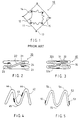
- Fig. 1 illustrates a unit-load sack known from the paper EP-0,158,361 , which is denoted generally with the reference numeral 10.
- the unit-load sack 10 consists of an outer sack 11 and of a separate inner sack 12.
- the outer sack 11 has folds 13, and the inner sack 12 has folds 14.
- sticky adhesive material 15 has been placed.
- the folds 14 with adhesive material 15 in the inner sack 12 are placed substantially halfway between the folds 13 with adhesive material 15 in the outer sack 11.
- the inner sack 12 expands and is glued onto the outer sack 11.
- the mode of positioning of the adhesive material as illustrated in Fig. 1 involves the numerous drawbacks that were described above.
- the unit-load sack is denoted generally with the reference numeral 20.
- adhesive material 23 is applied to the folded areas 24 of the outer sack 21 only, in the way indicated in the figure.
- adhesive is applied to the inner face of the outer sack 21, but not into the narrow space formed by a bend or fold 24 but, on the contrary, to the outer face of the folded area 24.
- adhesive areas 33 have been fitted to the inner face of the outer sack 31 in the unit-load sack 30, said adhesive areas being placed substantially opposite to one another and relatively far from the folded areas 34 of the outer sack 31.
- the inner sack can be fitted, for example, either in the way denoted with the reference numeral 32a or in the way denoted with the reference numeral 32b.
- This embodiment is inferior to that illustrated in Fig. 2, because the inner sack 32a or 32b meets the adhesive areas 33 very soon after the inner sack starts being filled.
- the inner sack 32a or 32b may even adhere to the outer sack 31 weakly before the inner sack is filled, but this is not harmful, because the adhesive material is an adhesive material whose adhesive capacity permits movements of the adhesive joint or joints between the inner sack 32a or 32b and the outer sack 31 as the inner sack is being filled with bulk goods.
- the inner sack 42 of the unit-load sack has been folded into a sort of a "wave form", and adhesive material has been applied to the areas 43.
- the adhesive areas 43 are placed on the outer face of the inner sack 42.
- the adhesive areas 43 are placed at a substantial distance from the wave ridge or wave ridges 44 of the inner sack 42 and from the wave bottom 45, in the area between the wave ridge 44 and the wave bottom 45.
- the embodiment shown in Fig. 5 is in the other respects the same as the embodiment shown in Fig. 4, but in the embodiment of Fig. 5 the adhesive areas 53 are placed at the edges of the folded inner sack 52 as far from the wave ridge 54 and from the wave bottom 55 as possible.
- the adhesive areas 53 adhere to the outer sack almost immediately in a way substantially similar to the embodiment as shown in Fig. 3. This solution is not detrimental either, because the adhesive material can be chosen in a way similar to the embodiment shown in Fig. 3.
- the inner sack 62 has been folded into the form of an almost closed ring, and the adhesive areas 63 are placed on the inner face of the inner sack 62 at the edges, which form the open point 64 provided in the shape of a folded ring of the inner sack 62.
- the solution operates substantially equally well as the embodiments as shown in Figs. 2 and 4 do.
- the inner sack 72 shown in Fig. 7 is a folded inner sack, and the adhesive areas 73 are placed on the outer face of the folded inner sack 72 at points from which the fold 74 starts being directed inwards.
- the solution shown in Fig. 7 operates substantially equally well as the solutions shown in Figs. 2, 4 and 6 do.
- the inner sack 82 shown in Fig. 8 has been bent into the shape of a substantially open U.
- the adhesive area 83 is placed in direct vicinity of the tip 84 of one branch of the U-section.
- the solution shown in this embodiment also operates substantially equally well as the solutions shown in Figs. 2, 4, 6 and 7 do.
- the inner sack 92 has been bent into the shape of a substantially oval ring, and the adhesive area 93 is placed in direct vicinity of one of the overlapping ends 94 of the bent inner sack 92.
- the inner sack 102 has been bent substantially in the same way as in the embodiment of Fig. 9, but the adhesive area 103 is placed substantially opposite to the area in which the ends 104 of the bent inner sack 102 overlap each other.
- the adhesive material preferably such an adhesive material is used whose adhesive capacity is sufficient to support the inner sack's own weight but which permits movements in the adhesive joint between the inner sack and the outer sack when the unit-load sack is being filled with bulk goods.
- a glue of low cohesion such as, for example, preferably a self-adhesive glue.
- the adhesive material it is possible to use, for example, a glue that is activated by the effect of outside conditions.
- One such adhesive material is a glue activated by the effect of UV radiation.
- a catalyst which produces adhesion of the adhesive material by the effect of UV radiation.
- an adhesive material it is also possible to use a glue that is activated by the effect of humidity contained in air, of rainwater, or equivalent.
- a glue that is activated by the effect of humidity contained in air, of rainwater, or equivalent.
- an adhesive material it is possible to add an inorganic or organic hygroscopic agent.
- an ethylvinylalcohol-based hygroscopic agent is highly suitable and usable for the purpose of the invention.
Landscapes
- Engineering & Computer Science (AREA)
- Mechanical Engineering (AREA)
- Making Paper Articles (AREA)
Description
Claims (16)
- A method for fixing the inner sack (22, 32a, 32b, 42, 52, 62, 72, 82, 92, 102) of a unit-load sack (20, 30) to the outer sack (21, 31), in which method the inner sack is fixed to the outer sack by using an adhesive material (23, 33, 43, 53, 63, 73, 83, 93, 103) applied exclusively either to the outer surface of the inner sack (22, 32a, 32b, 42, 52, 62, 72, 82, 92, 102) or to the inner surface of the outer sack (21, 31), characterized in that the adhesive material has an adhesion which permits movement of the adhesive joint between the inner sack (22, 32a, 32b, 42, 52, 62, 72, 82, 92, 102) and the outer sack (21, 31) when the unit-load sack (20, 30) is being filled with goods.
- A method as claimed in claim 1, characterized in that the inner sack (42) is folded substantially into wave form and that the adhesive material (43) is applied onto the outer surfaces of the inner sack (42) so as to constitute adhesive areas (43) which are placed at a substantial distance from the wave ridge (44) and from the wave bottom (45) of the inner sack (42).
- A method as claimed in claim 1, characterized in that the inner sack (52) is folded substantially into wave form and that the adhesive material (53) is applied onto the outer surfaces of the inner sack (52) so as to constitute adhesive areas (53) which are placed substantially at the edges of the wave formed inner sack (52).
- A method as claimed in claim 1, characterized in that the inner sack (62) is folded into the form of an almost closed ring and that the adhesive material (63) is applied onto the outer surfaces of the inner sack (62) so as to constitute adhesive areas (63) which are placed at the edges, and on the inwardly facing surfaces, of the folded sack, in the vicinity of the open point (64) of the almost closed ring.
- A method as claimed in claim 1, characterized in that the inner sack (72) is folded with two or more inwardly directed folds and that the adhesive material (73) is applied onto the outer surfaces of the inner sack (72) so as to constitute adhesive areas (73) positioned at points where the folds (74) start being directed inwards.
- A method as claimed in claim 1, characterized in that the inner sack (82) is bent into a substantially open U-shape and that the adhesive material (83) is applied onto the outer surface of the inner sack (82) in direct vicinity of at least one of the tips (84).
- A method as claimed in claim 1, characterized in that the inner sack (92) is bent substantially into an oval ring shape so that the ends of the inner sack (92) overlap each other, and that the adhesive material (93) is applied onto the outer surface of the inner sack (92) in direct vicinity of at least one of the overlapping ends (94).
- A method as claimed in claim 1, characterized in that the inner sack (102) is bent substantially into the shape of an oval ring so that the ends (104) of the inner sack (102) overlap each other, and that the adhesive material (103) is applied onto the outer surface of the inner sack (102) in an area that is placed substantially opposite to the area in which the ends (104) of the bent inner sack (102) overlap each other.
- A method as claimed in claim 1, characterized in that the outer sack (21) is folded with two or more inwardly directed folds and that the adhesive material (23) is applied to the inner surface of the outer sack (21) so as to constitute adhesive areas (23) positioned substantially at the tip of the inward fold.
- A method as claimed in claim 1, characterized in that the outer sack (31) is folded with two or more inwardly directed folds and that the adhesive material (33) has been applied to the inner surface of the outer sack (31) so as to constitute adhesive areas (33) which are placed substantially opposite to one another and substantially far from the folded areas (34) of the outer sack (31).
- A method as claimed in any one of the claims 1 to 10, characterized in that the adhesive material that is used is a glue of low cohesion, preferably a self-adhesive glue.
- A method as claimed in any one of the claims 1 to 10, characterized in that the adhesive material that is used is a glue that is activated by the effect of external conditions.
- A method as claimed in claim 12, characterized in that the adhesive material that is used is a glue that is activated by the effect of UV radiation.
- A method as claimed in claim 13, characterized in that to the adhesive material a catalyst is added which produces adhesion of the adhesive material by the effect of UV radiation.
- A method as claimed in claim 12, characterized in that the adhesive material that is used is a glue that is activated by the effect of humidity contained in air, of rainwater, or equivalent.
- A method as claimed in claim 15, characterized in that an inorganic or organic hygroscopic agent is added to the adhesive material.
Applications Claiming Priority (3)
| Application Number | Priority Date | Filing Date | Title |
|---|---|---|---|
| FI945686A FI102264B (en) | 1994-12-02 | 1994-12-02 | Method of attaching the inner bag of a large bag to the outer bag |
| FI945686 | 1994-12-02 | ||
| PCT/FI1995/000660 WO1996016882A1 (en) | 1994-12-02 | 1995-11-29 | Method for fixing the inner sack of a unit-load sack to the outer sack |
Publications (2)
| Publication Number | Publication Date |
|---|---|
| EP0793608A1 EP0793608A1 (en) | 1997-09-10 |
| EP0793608B1 true EP0793608B1 (en) | 1999-03-10 |
Family
ID=8541917
Family Applications (1)
| Application Number | Title | Priority Date | Filing Date |
|---|---|---|---|
| EP95938485A Expired - Lifetime EP0793608B1 (en) | 1994-12-02 | 1995-11-29 | Method for fixing the inner sack of a unit-load sack to the outer sack |
Country Status (3)
| Country | Link |
|---|---|
| EP (1) | EP0793608B1 (en) |
| FI (1) | FI102264B (en) |
| WO (1) | WO1996016882A1 (en) |
Family Cites Families (2)
| Publication number | Priority date | Publication date | Assignee | Title |
|---|---|---|---|---|
| DK150453C (en) * | 1984-04-12 | 1987-12-14 | Nyborg Plast | FLEXIBLE CONTAINER FOR TRANSPORT AND STORAGE OF LODGE |
| US4946291A (en) * | 1987-01-02 | 1990-08-07 | Schnaars Daniel R | Semi-bulk with liner |
-
1994
- 1994-12-02 FI FI945686A patent/FI102264B/en active
-
1995
- 1995-11-29 WO PCT/FI1995/000660 patent/WO1996016882A1/en not_active Ceased
- 1995-11-29 EP EP95938485A patent/EP0793608B1/en not_active Expired - Lifetime
Also Published As
| Publication number | Publication date |
|---|---|
| FI945686A0 (en) | 1994-12-02 |
| FI945686L (en) | 1996-06-03 |
| EP0793608A1 (en) | 1997-09-10 |
| FI102264B1 (en) | 1998-11-13 |
| FI102264B (en) | 1998-11-13 |
| WO1996016882A1 (en) | 1996-06-06 |
Similar Documents
| Publication | Publication Date | Title |
|---|---|---|
| US4580683A (en) | High security self-sealing mailing receptacle | |
| EP1239799B1 (en) | Ice pack with expandable opening | |
| CA2292648C (en) | Carton, carton blank and method for forming the carton | |
| US6176615B1 (en) | Side-folded bag or sack | |
| CA2372052C (en) | Multiwall paper bag | |
| US5465900A (en) | Pretaped container blanks | |
| JPH10509677A (en) | Carrying bag | |
| US5885262A (en) | Waste bag | |
| CA2066899A1 (en) | Dust filter bag | |
| US5913764A (en) | Method of manufacturing flat-bottom bags with a glued-on bottom lining | |
| US4566131A (en) | Valved bag | |
| US4453270A (en) | Pasted valve stepped end bag | |
| CA1163964A (en) | Pinch bottom valve bag | |
| US20050211755A1 (en) | Container with adhesive seal tapes | |
| EP0793608A1 (en) | Method for fixing the inner sack of a unit-load sack to the outer sack | |
| CA1207248A (en) | Edge-bonding of sheet material | |
| SE9300359D0 (en) | BEHAALLARSAECK | |
| US4382538A (en) | Valved lined container | |
| CA2635757A1 (en) | Roll of longitudinally folded masking material | |
| AU611890B2 (en) | Gable-top container closure system | |
| EP0400826B1 (en) | Flexible container | |
| US2751142A (en) | Bags | |
| AU715771B2 (en) | Safety bag | |
| EP0107500B1 (en) | Heavy duty bag | |
| JP2565413Y2 (en) | Bag body with opening means |
Legal Events
| Date | Code | Title | Description |
|---|---|---|---|
| PUAI | Public reference made under article 153(3) epc to a published international application that has entered the european phase |
Free format text: ORIGINAL CODE: 0009012 |
|
| 17P | Request for examination filed |
Effective date: 19970527 |
|
| AK | Designated contracting states |
Kind code of ref document: A1 Designated state(s): BE FR GB NL |
|
| 17Q | First examination report despatched |
Effective date: 19980203 |
|
| GRAG | Despatch of communication of intention to grant |
Free format text: ORIGINAL CODE: EPIDOS AGRA |
|
| GRAG | Despatch of communication of intention to grant |
Free format text: ORIGINAL CODE: EPIDOS AGRA |
|
| GRAH | Despatch of communication of intention to grant a patent |
Free format text: ORIGINAL CODE: EPIDOS IGRA |
|
| GRAH | Despatch of communication of intention to grant a patent |
Free format text: ORIGINAL CODE: EPIDOS IGRA |
|
| GRAA | (expected) grant |
Free format text: ORIGINAL CODE: 0009210 |
|
| AK | Designated contracting states |
Kind code of ref document: B1 Designated state(s): BE FR GB NL |
|
| ET | Fr: translation filed | ||
| PLBE | No opposition filed within time limit |
Free format text: ORIGINAL CODE: 0009261 |
|
| STAA | Information on the status of an ep patent application or granted ep patent |
Free format text: STATUS: NO OPPOSITION FILED WITHIN TIME LIMIT |
|
| 26N | No opposition filed | ||
| REG | Reference to a national code |
Ref country code: GB Ref legal event code: IF02 |
|
| PGFP | Annual fee paid to national office [announced via postgrant information from national office to epo] |
Ref country code: FR Payment date: 20031029 Year of fee payment: 9 |
|
| PGFP | Annual fee paid to national office [announced via postgrant information from national office to epo] |
Ref country code: GB Payment date: 20031126 Year of fee payment: 9 |
|
| PGFP | Annual fee paid to national office [announced via postgrant information from national office to epo] |
Ref country code: NL Payment date: 20031128 Year of fee payment: 9 |
|
| PGFP | Annual fee paid to national office [announced via postgrant information from national office to epo] |
Ref country code: BE Payment date: 20031209 Year of fee payment: 9 |
|
| PG25 | Lapsed in a contracting state [announced via postgrant information from national office to epo] |
Ref country code: GB Free format text: LAPSE BECAUSE OF NON-PAYMENT OF DUE FEES Effective date: 20041129 |
|
| PG25 | Lapsed in a contracting state [announced via postgrant information from national office to epo] |
Ref country code: BE Free format text: LAPSE BECAUSE OF NON-PAYMENT OF DUE FEES Effective date: 20041130 |
|
| BERE | Be: lapsed |
Owner name: *UPM-KYMMENE OY Effective date: 20041130 |
|
| PG25 | Lapsed in a contracting state [announced via postgrant information from national office to epo] |
Ref country code: NL Free format text: LAPSE BECAUSE OF NON-PAYMENT OF DUE FEES Effective date: 20050601 |
|
| GBPC | Gb: european patent ceased through non-payment of renewal fee |
Effective date: 20041129 |
|
| PG25 | Lapsed in a contracting state [announced via postgrant information from national office to epo] |
Ref country code: FR Free format text: LAPSE BECAUSE OF NON-PAYMENT OF DUE FEES Effective date: 20050729 |
|
| NLV4 | Nl: lapsed or anulled due to non-payment of the annual fee |
Effective date: 20050601 |
|
| REG | Reference to a national code |
Ref country code: FR Ref legal event code: ST |
|
| BERE | Be: lapsed |
Owner name: *UPM-KYMMENE OY Effective date: 20041130 |