EP0793440B1 - Laryngoscope pressure sensor and alarm - Google Patents
Laryngoscope pressure sensor and alarm Download PDFInfo
- Publication number
- EP0793440B1 EP0793440B1 EP95943576A EP95943576A EP0793440B1 EP 0793440 B1 EP0793440 B1 EP 0793440B1 EP 95943576 A EP95943576 A EP 95943576A EP 95943576 A EP95943576 A EP 95943576A EP 0793440 B1 EP0793440 B1 EP 0793440B1
- Authority
- EP
- European Patent Office
- Prior art keywords
- laryngoscope
- alarm
- sensor
- alarm system
- sensing means
- Prior art date
- Legal status (The legal status is an assumption and is not a legal conclusion. Google has not performed a legal analysis and makes no representation as to the accuracy of the status listed.)
- Expired - Lifetime
Links
- 125000006850 spacer group Chemical group 0.000 claims description 14
- 239000000853 adhesive Substances 0.000 claims description 10
- 230000001070 adhesive effect Effects 0.000 claims description 10
- 239000004020 conductor Substances 0.000 claims description 8
- 238000000576 coating method Methods 0.000 claims 1
- 239000012528 membrane Substances 0.000 abstract description 18
- 239000000463 material Substances 0.000 description 15
- 229920002799 BoPET Polymers 0.000 description 3
- 229920006370 Kynar Polymers 0.000 description 3
- 229920001971 elastomer Polymers 0.000 description 3
- 239000000806 elastomer Substances 0.000 description 3
- 238000001465 metallisation Methods 0.000 description 3
- 229920002635 polyurethane Polymers 0.000 description 3
- 239000004814 polyurethane Substances 0.000 description 3
- 230000035945 sensitivity Effects 0.000 description 3
- 210000003437 trachea Anatomy 0.000 description 3
- 210000003811 finger Anatomy 0.000 description 2
- 239000002184 metal Substances 0.000 description 2
- 206010002091 Anaesthesia Diseases 0.000 description 1
- 239000002033 PVDF binder Substances 0.000 description 1
- 239000004820 Pressure-sensitive adhesive Substances 0.000 description 1
- 230000037005 anaesthesia Effects 0.000 description 1
- 229920002457 flexible plastic Polymers 0.000 description 1
- 210000004704 glottis Anatomy 0.000 description 1
- 210000000867 larynx Anatomy 0.000 description 1
- 238000012986 modification Methods 0.000 description 1
- 230000004048 modification Effects 0.000 description 1
- 230000007935 neutral effect Effects 0.000 description 1
- 238000011017 operating method Methods 0.000 description 1
- 239000004033 plastic Substances 0.000 description 1
- 229920003023 plastic Polymers 0.000 description 1
- 229920002981 polyvinylidene fluoride Polymers 0.000 description 1
- 230000000135 prohibitive effect Effects 0.000 description 1
- 239000007921 spray Substances 0.000 description 1
- 238000001356 surgical procedure Methods 0.000 description 1
- 210000003813 thumb Anatomy 0.000 description 1
- 238000002627 tracheal intubation Methods 0.000 description 1
Images

Classifications
-
- A—HUMAN NECESSITIES
- A61—MEDICAL OR VETERINARY SCIENCE; HYGIENE
- A61B—DIAGNOSIS; SURGERY; IDENTIFICATION
- A61B1/00—Instruments for performing medical examinations of the interior of cavities or tubes of the body by visual or photographical inspection, e.g. endoscopes; Illuminating arrangements therefor
- A61B1/267—Instruments for performing medical examinations of the interior of cavities or tubes of the body by visual or photographical inspection, e.g. endoscopes; Illuminating arrangements therefor for the respiratory tract, e.g. laryngoscopes, bronchoscopes
-
- A—HUMAN NECESSITIES
- A61—MEDICAL OR VETERINARY SCIENCE; HYGIENE
- A61B—DIAGNOSIS; SURGERY; IDENTIFICATION
- A61B1/00—Instruments for performing medical examinations of the interior of cavities or tubes of the body by visual or photographical inspection, e.g. endoscopes; Illuminating arrangements therefor
- A61B1/00002—Operational features of endoscopes
- A61B1/00043—Operational features of endoscopes provided with output arrangements
- A61B1/00055—Operational features of endoscopes provided with output arrangements for alerting the user
-
- A—HUMAN NECESSITIES
- A61—MEDICAL OR VETERINARY SCIENCE; HYGIENE
- A61B—DIAGNOSIS; SURGERY; IDENTIFICATION
- A61B17/00—Surgical instruments, devices or methods
- A61B2017/00017—Electrical control of surgical instruments
- A61B2017/00115—Electrical control of surgical instruments with audible or visual output
- A61B2017/00119—Electrical control of surgical instruments with audible or visual output alarm; indicating an abnormal situation
-
- A—HUMAN NECESSITIES
- A61—MEDICAL OR VETERINARY SCIENCE; HYGIENE
- A61B—DIAGNOSIS; SURGERY; IDENTIFICATION
- A61B2562/00—Details of sensors; Constructional details of sensor housings or probes; Accessories for sensors
- A61B2562/02—Details of sensors specially adapted for in-vivo measurements
- A61B2562/0247—Pressure sensors
Definitions
- This invention relates generally to pressure sensors and, more particularly, to a replaceable pressure sensing system for detecting undue pressure applied to a patient's teeth by a laryngoscope.
- Medical personnel such as anesthesiologists, use laryngoscopes to gain access to the trachea for inserting tubes during surgery.
- the tubes are introduced past the glottis and into the trachea or windpipe for permitting the patient to breath and for administering anesthesia.
- the patient's head is placed in a neutral or sniffing position and the tip of a laryngoscope blade is inserted into the vallecula.
- the laryngoscope is held with the index finger and thumb of the left hand and the patient's chin is held with the ring and middle fingers of the same hand.
- the laryngoscope handle and blade are pulled away from the patient at, preferably, a 45° angle. Endotracheal tubes are then passed through the patient's mouth or throat along the laryngoscope blade and into the trachea.
- Laryngoscopes having either a pivotally mounted laryngoscope flange or a built-in pressure plate and alarm have been described in the art for alleviating this problem.
- U.S. Patent No. 4,295,465, issued to Racz et al. describes a laryngoscope blade including an elongated base member carrying a projecting flange.
- the base member has a rear portion, a mid-portion and a tip portion, wherein the rear portion is securely attached to the laryngoscope handle.
- the flange is pivotally connected by resilient means to the base member and projects upward along the rear and mid-portions such that when the blade is inserted into a patient's mouth, the flange may contact the patient's upper teeth and pivot with respect to the base member. This limits pressure applied to the upper teeth as the flange pivots; however, there is no alarm for indicating when pivoting has ended and excess pressure is being applied.
- the rotatable flange is an integral part of the laryngoscope, to utilize this feature a complete laryngoscope must be purchased. This may be cost prohibitive.
- U.S. Patent No. 4,384,570 discloses a laryngoscope including a pressure plate positioned on the flange for detecting undue pressure applied to the upper teeth.
- the plate is electrically connected to a battery and alarm situated in the handle. An electrical signal is transmitted to the alarm for alerting the user thereof to pressure being applied to the plate.
- the laryngoscope described by Roberts includes a handle section having rigid and movable portions adapted to be pivoted and locked at a desired position.
- the pressure plate system is not a replaceable sterile unit, separable from the handle configuration.
- the pressure sensing system described by Roberts is not independently functioning dental protection which can be supplied as a retrofit device for currently used laryngoscopes.
- the pressure plate does not cushion the contact with the teeth.
- a sterile, replaceable laryngoscope pressure sensing system having cushioning properties is needed.
- Sensors for detecting pressure with equal sensitivity at any point along the length thereof may be of the linear membrane variety or may use piezoelectric film, such as the film used in U.S. Patent No. 4,488,873, issued to Bloomfield et al which describes a dental impression strip prepared from a piezoelectric film coated with conventional deformable wax impression material. The film and wax assembly is folded to provide information about the forces exerted during occlusal analysis.
- the film is KYNAR® piezofilm, a polyvinylidene fluoride product of the Pennwalt Corporation of Philadelphia, Pennsylvania, which may be configured for use in the present invention.
- Another object of the invention is to provide a sterile, replaceable pressure sensing system, including a battery and an alarm, for a laryngoscope.
- Yet another object of the invention is to provide a sterile, replaceable pressure sensor for a variety of laryngoscopes, including disposable and foldable laryngoscopes.
- Still another object of the invention is to provide a sterile, replaceable pressure sensing system for a variety of laryngoscopes, including disposable and foldable laryngoscopes.
- a further object of the invention is to provide a sterile, replaceable pressure sensor adapted to be used on a laryngoscope for detecting pressure applied at any point along the length thereof with equal sensitivity and which exhibits cushioning properties to prevent tooth damage.
- a still further object of the invention is to provide a sterile, replaceable pressure sensor and alarm for detecting pressure from a patient's teeth and indicating this condition.
- Yet a still further object of the invention is to provide a linear membrane pressure sensor for detecting pressure applied by teeth along the length thereof.
- Yet still another object of the invention is to provide a piezoelectric film laryngoscope pressure sensor for detecting pressure applied by teeth along the length thereof.
- a replaceable assembly including an elongated, resilient sensor or switch electrically connectable to a battery and an audio warning system or alarm.
- the elongated sensor is of the type wherein pressure applied at any point along the length thereof activates the sensor.
- the battery and alarm may be carried by the elongated sensor to form a single, replaceable unit or, alternatively, they may be more permanently attached to the laryngoscope. In the latter situation, the sensor is releasably connected in circuit with the battery and alarm device.
- the pressure sensor of the present invention may be discarded if unsterile or damaged and a replacement inexpensively and immediately provided.
- the elongated sensor includes a first resilient, flexible elongated member and a second flexible elongated member held in parallel spaced relation and having a pressure sensor situated therebetween.
- the sensor is a linear membrane switch including two conductive ribbons or members carried in spaced face-to-face relation on opposite sides of an apertured spacer layer.
- the first member preferably made from polyurethane, carries a first conductive ribbon along the length thereof and the second member, preferably made from a Mylar® film, carries a second conductive ribbon along the length thereof.
- the members are separated by a spacer strip made of a suitable elastomer. The spacer resides between the first and second conductive ribbons to normally maintain them in spaced relation.
- the second member carries an adhesive backing on the exposed surface thereof for adhering the linear membrane switch to the laryngoscope.
- a piezoelectric film such as KYNAR® piezofilm
- first and second members to form an elongated pressure sensor or switch.
- the members may be made of the same material used in the linear membrane switch embodiment.
- An operational amplifier circuit such as the one described in U.S. Patent No. 4,488,873, issued to Bloomfield et al., and shown at Figure 5 in that patent, may be used to convert the high impedance output from the piezofilm assembly to a low impedance voltage output which can be transmitted to an alarm. The voltage output and, thus, the alarm intensity varies with the pressure applied to the piezofilm.
- the amount of force required to activate the sensor will depend on the stiffness, thickness and resiliency characteristics of the first and second members. In the conductive ribbon embodiment, the amount of force required will also depend on the thickness and resiliency of the spacer, and the width of the opening between ribbons.
- the first and second members, and the spacer may be manufactured with material having varying densities, affecting the amount of force required to activate the sensor. The cushioning afforded by the material chosen improves the dental protection provided by the resilient elongated sensor when tooth contact is made. Thus, sensors made of material having different thicknesses and resiliency characteristics may be built and chosen to accommodate the various needs of different patients.
- the battery, alarm and any required circuitry may be carried by the sensor of either embodiment. Since the present invention is a replaceable device, the battery may be small and totally encapsulated by the members, or simply secured to either member.
- the alarm may be a visible or audible alarm encapsulated or secured to either member, such that the visible alarm may be seen and the audible alarm may be heard.
- any required circuitry may be encapsulated or simply secured to either member.
- the battery, the alarm and any required circuitry may be carried by the laryngoscope itself. In such a case, the sensor of the present invention is replaceable.
- the battery employed may be that used to conventionally illuminate the airway and the alarm device may be mounted to the handle of the laryngoscope in any manner, such as with screws or adhesive.
- the sensor portion of either embodiment may be long enough to attach to the flange and the handle of the laryngoscope or, in the alternative, the sensor may be situated only on the laryngoscope flange. In the latter situation, the sensor is electrically connected, such as with wires, to the battery, alarm and any required circuitry which may be carried by the member portion attached to the handle or, in the alternative, carried by the laryngoscope itself.
- a pressure sensor is attached to the flange and wires connect the sensor to the battery, alarm and required circuitry carried by the member portion attached to the handle.
- An expandable member portion and excess wire is provided between the sensor and the alarm electronics so the pressure sensor and alarm system may be attached to a laryngoscope in the folded position which may then be subsequently deployed or refolded without affecting the pressure sensor and alarm system.
- a pressure sensor and alarm system embodying the ideas of the present invention and indicated generally by numeral 2
- the pressure sensor 4 preferably comprises an elongated, flexible portion for detecting pressure with essentially equal sensitivity at any position along the length thereof.
- the pressure sensor 4 is made to complete a circuit between the alarm 8, which may be either an audible or a visible indicator, and a battery 6 when a predetermined pressure is applied.
- the opposed major surfaces of the system 2 are preferably made of a resilient, flexible material.
- the back side carries a suitable pressure sensitive adhesive 10 which is protected prior to use by a backing material 12, such as a conventional release paper.
- the paper may be peeled away to uncover the adhesive 10 allowing the pressure sensor and alarm 2 to be adhered to a laryngoscope, indicated by the numeral 14 and shown in Figure 2.
- the pressure sensor and alarm system 2 may be releasably attached in another manner to the laryngoscope 14 or another device.
- the laryngoscope 14 includes a handle portion 16 and a flange 20 attached to a blade 18.
- the flexible pressure sensor portion 4 can be made to conform to the illustrated surfaces of the laryngoscope 14 and the battery 6 and alarm 8 positioned next to the handle 16.
- the tip 22 of the laryngoscope 14 is passed through the mouth of the patient and into the throat area.
- the handle 16 is pulled away from the mouth at approximately a 45° angle to pull down on the mouth and open the throat passageway. Medical personnel may then look into the throat area and tubes may be inserted.
- the handle 16 of the laryngoscope 14 is pulled away from the mouth, the patient's upper front teeth 24 are sometimes used as a fulcrum. If a predetermined pressure is exceeded, the upper teeth 24 pushing on the pressure sensor 4 will cause the alarm 8 to be activated.
- the pressure sensor portion 4 both cushions the teeth and senses when undo pressure is being exerted by the laryngoscope 14. The alarm 8 notifies the user thereof to ease back on the laryngoscope 14.
- the pressure sensor portion 4 is either a linear membrane switch or a piezoelectric film pressure sensor.
- the linear membrane switch embodiment indicated generally by the numeral 30, includes a first elongated membrane strip 32 and a second elongated membrane strip 34.
- First and second strip members 32 and 34 extend the full length of the linear membrane system 30 and may be made from the same flexible material.
- the first strip member 32 is made from a resilient plastic material, such as polyurethane
- the second member 34 is made from a flexible plastic material, such as MYLAR® film.
- Spacer 36 made from a suitable elastomer, holds strip members 32 and 34 in spaced relation and defines a contact area 38 between strip members 32 and 34.
- a pattern of metalization comprising two elongated conductive ribbons 40 and 42 are carried in spaced, face-to-face relation by strip members 32 and 34, respectively, such that pressure applied to strip members 32 and 34 urges the conductive ribbons 40 and 42 toward one another.
- the alarm 8 and battery 6 are press fit into the first strip member 32.
- the alarm 8 is activated when conductive ribbons 40 and 42 are shorted together by a predetermined pressure applied to the first and second strip members 32 and 34.
- the pressure required varies depending on the characteristics of the material used to make members 32 and 34, the distance conductive ribbons 40 and 42 are held apart and the characteristics of the material used to make the spacer 36.
- the first conductive ribbon 40 is connected to alarm 8 with wire 44 and the second conductive ribbon 42 is connected to the battery 6 with wire 46.
- the battery 6 is also in electrical contact with the alarm 8. Contacting the elongated conductive ribbons 40 and 42 together completes the circuit and activates the alarm 8 to notify the user thereof that the predetermined pressure limit has been reached.
- the linear membrane embodiment 30 may be adhered to the laryngoscope 14 in any manner and in the preferred embodiment, an adhesive 10 is applied to the second elongated strip member 34 and covered with release paper layer 12.
- the membrane switch embodiment 30 is adhered to the laryngoscope 14 by peeling the release paper 12 away and pressing the adhesive surface to the flange 20 and handle 16 of the laryngoscope 14.
- the pressure sensor is a piezoelectric film assembly, indicated by the numeral 50, including first and second elongated strip members 52 and 54 held in spaced relation.
- the first member 52 is made of polyurethane and the second member 54 is made of MYLAR®.
- Spacer 56 comprise a metallization pattern and made of a suitable elastomer, defines a pressure sensor area 58 between strip members 52 and 54.
- An electronic circuit 60 converts the output of a piezoelectric film 62 from a high impedance signal to a low impedance voltage signal, which is sent to the alarm 8.
- the electronic circuit 60, battery 6 and alarm device 8 are press fit into the first strip member 52.
- the pressure sensor of the piezoelectric film embodiment 50 includes a piezoelectric film member 62, made from a material such as KYNAR®, and having metal electrodes 64 and 66 spray coated or otherwise attached to the opposed major surfaces.
- the metal electrodes 64 and 66 are electrically connected to the electronic circuit 60 by wires 68 and 70.
- the electronic circuit 60 is in electrical contact with the alarm 8 and the battery 6 and wire 72 serves as a second connection between the battery 6 and the circuit 60.
- the piezoelectric film embodiment 50 of the present invention cushions the teeth and indicates to the user thereof the amount of pressure being applied.
- Either embodiment of the pressure sensing portion 4 may be supplied in a sterile pack as an independent unit which can be releasably attached to a reusable or disposable laryngoscope 14.
- the linear membrane switch embodiment 30 is attached to the flange 20 and handle 16 of the laryngoscope 14.
- the pressure sensing portion 4 includes first and second elongated strip members 32 and 34 carrying elongated conductive ribbons 40 and 42 in spaced relation. Contacts 90 and 92 are provided for connecting the pressure sensing portion 4 through wires 94 and 96 to the battery 6 and alarm 8 carried in the handle 16. Wire 98 connects the battery 6 and alarm 8. The pressure sensor portion 4 may then be replaced after each use.
- the pressure sensing portion 4 of the piezoelectric film embodiment 50 may be adhered to the flange 20 of a laryngoscope 14 wherein the handle 16 carries the electric circuit 60, the battery 6 and the alarm 8. Also, in the linear membrane embodiment 30, the alarm 8 may be carried by the pressure sensing portion 4 with only the battery 6 situated in the handle 16 and, in the piezoelectric film embodiment 50, the alarm 8 and the electric circuit 60 may be carried by the pressure sensing portion 4 with only the battery 6 situated in the handle 16.
- an expandable, flexible member portion 100 is formed in the first and second members between the sensor 102 and alarm portion 104.
- the sensor 102 and alarm portion 104 are attached, such as with a releasable adhesive, to a laryngoscope.
- the laryngoscope is a foldable laryngoscope 106 having a handle 108, blade 110 and flange 112.
- the sensor 102 is releasably attached to the flange 112 and the alarm portion 104 is releasably attached to the handle 108.
- the accordion like flexible member portion 100 is not attached to the foldable laryngoscope 106.
- the sensor 102 may be either the linear membrane switch or the piezoelectric film sensor.
- the sensor 102 shown in Figures 11 and 12, is the linear membrane switch, which is electrically connected to the alarm 8 and battery 6 secured in the alarm portion 104.
- Wires 114 and 116 electrically connect the sensor 102 to the battery 6 and alarm 8.
- the electrical connection could also be made with an expandable conductive material attached to the folds of the expandable, flexible member portion 100.
- the wires 114 and 116 are long enough to reach around the folding end 118 of the foldable laryngoscope 106 when it is in the folded position, as shown in Figure 12. When the foldable laryngoscope 106 is deployed, as shown in Figure 11, the excess wire is stored in the expandable, flexible member portion 100.
Landscapes
- Health & Medical Sciences (AREA)
- Life Sciences & Earth Sciences (AREA)
- Surgery (AREA)
- Biomedical Technology (AREA)
- Medical Informatics (AREA)
- Optics & Photonics (AREA)
- Pathology (AREA)
- Radiology & Medical Imaging (AREA)
- Biophysics (AREA)
- Engineering & Computer Science (AREA)
- Physics & Mathematics (AREA)
- Heart & Thoracic Surgery (AREA)
- Nuclear Medicine, Radiotherapy & Molecular Imaging (AREA)
- Molecular Biology (AREA)
- Animal Behavior & Ethology (AREA)
- General Health & Medical Sciences (AREA)
- Public Health (AREA)
- Veterinary Medicine (AREA)
- Otolaryngology (AREA)
- Physiology (AREA)
- Pulmonology (AREA)
- Endoscopes (AREA)
Abstract
Description
- This invention relates generally to pressure sensors and, more particularly, to a replaceable pressure sensing system for detecting undue pressure applied to a patient's teeth by a laryngoscope.
- Medical personnel, such as anesthesiologists, use laryngoscopes to gain access to the trachea for inserting tubes during surgery. The tubes are introduced past the glottis and into the trachea or windpipe for permitting the patient to breath and for administering anesthesia.
- To insert an endotracheal tube, the patient's head is placed in a neutral or sniffing position and the tip of a laryngoscope blade is inserted into the vallecula. The laryngoscope is held with the index finger and thumb of the left hand and the patient's chin is held with the ring and middle fingers of the same hand. To expose the larynx, the laryngoscope handle and blade are pulled away from the patient at, preferably, a 45° angle. Endotracheal tubes are then passed through the patient's mouth or throat along the laryngoscope blade and into the trachea.
- During intubation, the back of the laryngoscope blade, or the laryngoscope flange, frequently contacts the patient's upper front teeth, which are used as a fulcrum. This may result in damage to the patient's teeth. Laryngoscopes having either a pivotally mounted laryngoscope flange or a built-in pressure plate and alarm have been described in the art for alleviating this problem.
- U.S. Patent No. 4,295,465, issued to Racz et al., describes a laryngoscope blade including an elongated base member carrying a projecting flange. The base member has a rear portion, a mid-portion and a tip portion, wherein the rear portion is securely attached to the laryngoscope handle. The flange is pivotally connected by resilient means to the base member and projects upward along the rear and mid-portions such that when the blade is inserted into a patient's mouth, the flange may contact the patient's upper teeth and pivot with respect to the base member. This limits pressure applied to the upper teeth as the flange pivots; however, there is no alarm for indicating when pivoting has ended and excess pressure is being applied. Also, since the rotatable flange is an integral part of the laryngoscope, to utilize this feature a complete laryngoscope must be purchased. This may be cost prohibitive.
- U.S. Patent No. 4,384,570, issued to Roberts, discloses a laryngoscope including a pressure plate positioned on the flange for detecting undue pressure applied to the upper teeth. The plate is electrically connected to a battery and alarm situated in the handle. An electrical signal is transmitted to the alarm for alerting the user thereof to pressure being applied to the plate. The laryngoscope described by Roberts includes a handle section having rigid and movable portions adapted to be pivoted and locked at a desired position. The pressure plate system is not a replaceable sterile unit, separable from the handle configuration. Thus, the pressure sensing system described by Roberts is not independently functioning dental protection which can be supplied as a retrofit device for currently used laryngoscopes. Also, the pressure plate does not cushion the contact with the teeth. A sterile, replaceable laryngoscope pressure sensing system having cushioning properties is needed.
- Such a system, must be equally sensitive to pressure applied at any point along the sensor. Devices described in U.S. Patent No. 3,888,117, issued to Lewis, and U.S. Patent No. 4,426,884, issued to Polchaninoff are not well suited to this. Each of these patents describe a planar electrical conductor held in spaced relation to a plurality of spaced electrical contacts. Pressure applied to the planar conductor relative to the contacts urges the two together. Using these devices to detect pressure applied by teeth may give inconsistent and unreliable results since, on some occasions, the teeth may be situated directly over an electrical contact and on others, the teeth may be between contacts.
- Sensors for detecting pressure with equal sensitivity at any point along the length thereof may be of the linear membrane variety or may use piezoelectric film, such as the film used in U.S. Patent No. 4,488,873, issued to Bloomfield et al which describes a dental impression strip prepared from a piezoelectric film coated with conventional deformable wax impression material. The film and wax assembly is folded to provide information about the forces exerted during occlusal analysis. The film is KYNAR® piezofilm, a polyvinylidene fluoride product of the Pennwalt Corporation of Philadelphia, Pennsylvania, which may be configured for use in the present invention.
- It is accordingly a principal object of the present invention to provide a sterile, replaceable pressure sensor for a laryngoscope.
- Another object of the invention is to provide a sterile, replaceable pressure sensing system, including a battery and an alarm, for a laryngoscope.
- Yet another object of the invention is to provide a sterile, replaceable pressure sensor for a variety of laryngoscopes, including disposable and foldable laryngoscopes.
- Still another object of the invention is to provide a sterile, replaceable pressure sensing system for a variety of laryngoscopes, including disposable and foldable laryngoscopes.
- A further object of the invention is to provide a sterile, replaceable pressure sensor adapted to be used on a laryngoscope for detecting pressure applied at any point along the length thereof with equal sensitivity and which exhibits cushioning properties to prevent tooth damage.
- A still further object of the invention is to provide a sterile, replaceable pressure sensor and alarm for detecting pressure from a patient's teeth and indicating this condition.
- Yet a still further object of the invention is to provide a linear membrane pressure sensor for detecting pressure applied by teeth along the length thereof.
- Yet still another object of the invention is to provide a piezoelectric film laryngoscope pressure sensor for detecting pressure applied by teeth along the length thereof.
- Other objects, features and advantages of the present invention will become apparent to those skilled in the art through familiarity with the summary of the invention, detailed description, claims and drawings herein.
- The foregoing objects of the present invention are attained by providing a replaceable assembly including an elongated, resilient sensor or switch electrically connectable to a battery and an audio warning system or alarm. The elongated sensor is of the type wherein pressure applied at any point along the length thereof activates the sensor. The battery and alarm may be carried by the elongated sensor to form a single, replaceable unit or, alternatively, they may be more permanently attached to the laryngoscope. In the latter situation, the sensor is releasably connected in circuit with the battery and alarm device. Thus, the pressure sensor of the present invention may be discarded if unsterile or damaged and a replacement inexpensively and immediately provided.
- The elongated sensor includes a first resilient, flexible elongated member and a second flexible elongated member held in parallel spaced relation and having a pressure sensor situated therebetween. In one embodiment, the sensor is a linear membrane switch including two conductive ribbons or members carried in spaced face-to-face relation on opposite sides of an apertured spacer layer. The first member, preferably made from polyurethane, carries a first conductive ribbon along the length thereof and the second member, preferably made from a Mylar® film, carries a second conductive ribbon along the length thereof. The members are separated by a spacer strip made of a suitable elastomer. The spacer resides between the first and second conductive ribbons to normally maintain them in spaced relation. The second member carries an adhesive backing on the exposed surface thereof for adhering the linear membrane switch to the laryngoscope.
- In another embodiment, a piezoelectric film, such as KYNAR® piezofilm, is coated on each side with metallic contact material and the coated film is sandwiched between first and second members to form an elongated pressure sensor or switch. The members may be made of the same material used in the linear membrane switch embodiment. An operational amplifier circuit, such as the one described in U.S. Patent No. 4,488,873, issued to Bloomfield et al., and shown at Figure 5 in that patent, may be used to convert the high impedance output from the piezofilm assembly to a low impedance voltage output which can be transmitted to an alarm. The voltage output and, thus, the alarm intensity varies with the pressure applied to the piezofilm.
- In either embodiment, the amount of force required to activate the sensor will depend on the stiffness, thickness and resiliency characteristics of the first and second members. In the conductive ribbon embodiment, the amount of force required will also depend on the thickness and resiliency of the spacer, and the width of the opening between ribbons. The first and second members, and the spacer may be manufactured with material having varying densities, affecting the amount of force required to activate the sensor. The cushioning afforded by the material chosen improves the dental protection provided by the resilient elongated sensor when tooth contact is made. Thus, sensors made of material having different thicknesses and resiliency characteristics may be built and chosen to accommodate the various needs of different patients.
- The battery, alarm and any required circuitry may be carried by the sensor of either embodiment. Since the present invention is a replaceable device, the battery may be small and totally encapsulated by the members, or simply secured to either member. The alarm may be a visible or audible alarm encapsulated or secured to either member, such that the visible alarm may be seen and the audible alarm may be heard. Similarly, any required circuitry may be encapsulated or simply secured to either member. In the alternative, the battery, the alarm and any required circuitry may be carried by the laryngoscope itself. In such a case, the sensor of the present invention is replaceable. Of course, the battery employed may be that used to conventionally illuminate the airway and the alarm device may be mounted to the handle of the laryngoscope in any manner, such as with screws or adhesive.
- The sensor portion of either embodiment may be long enough to attach to the flange and the handle of the laryngoscope or, in the alternative, the sensor may be situated only on the laryngoscope flange. In the latter situation, the sensor is electrically connected, such as with wires, to the battery, alarm and any required circuitry which may be carried by the member portion attached to the handle or, in the alternative, carried by the laryngoscope itself. In one embodiment, a pressure sensor is attached to the flange and wires connect the sensor to the battery, alarm and required circuitry carried by the member portion attached to the handle. An expandable member portion and excess wire is provided between the sensor and the alarm electronics so the pressure sensor and alarm system may be attached to a laryngoscope in the folded position which may then be subsequently deployed or refolded without affecting the pressure sensor and alarm system.
-
- Figure 1 is a side view of a pressure sensor and alarm of the present invention;
- Figure 2 is a perspective view of a pressure sensor and alarm of the present invention attached to a laryngoscope;
- Figure 3 is a side elevational view of a laryngoscope pressure sensor and alarm attached to a laryngoscope and contacting the upper front teeth of a patient;
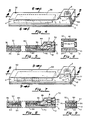
- Figure 4 is an enlarged perspective view of a linear membrane pressure sensor and alarm of the present invention showing the alarm device and battery in dashed lines;
- Figure 5 is a sectional view of Figure 4 taken along
the
line 5--5 thereof; - Figure 6 is an exploded sectional view of Figure 4
taken along the
line 6--6 thereof; - Figure 7 is an enlarged perspective view of a piezoelectric film pressure sensor and alarm of the present invention showing the alarm device, electronic circuit and battery in dashed lines;
- Figure 8 is a sectional view of Figure 7 taken along
the
line 8--8 thereof; - Figure 9 is a sectional view of Figure 7 taken along the line 9--9 thereof;
- Figure 10 is a side view of a laryngoscope sensor pad connected to a laryngoscope carrying a battery and alarm, shown with parts cut away;
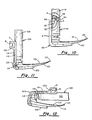
- Figure 11 is a side view of a laryngoscope pressure sensor and alarm having an expandable member portion wherein the pressure sensor and alarm is attached to a foldable laryngoscope; and
- Figure 12 is a side view of the foldable laryngoscope and the pressure sensor and alarm system of Figure 11 in the folded position.
-
- As shown in Figure 1, one embodiment of a pressure sensor and alarm system embodying the ideas of the present invention and indicated generally by
numeral 2, is seen to include apressure sensor portion 4 electrically connected to abattery 6 and analarm device 8. Thepressure sensor 4 preferably comprises an elongated, flexible portion for detecting pressure with essentially equal sensitivity at any position along the length thereof. Thepressure sensor 4 is made to complete a circuit between thealarm 8, which may be either an audible or a visible indicator, and abattery 6 when a predetermined pressure is applied. The opposed major surfaces of thesystem 2 are preferably made of a resilient, flexible material. The back side carries a suitable pressure sensitive adhesive 10 which is protected prior to use by abacking material 12, such as a conventional release paper. The paper may be peeled away to uncover the adhesive 10 allowing the pressure sensor andalarm 2 to be adhered to a laryngoscope, indicated by the numeral 14 and shown in Figure 2. Of course, the pressure sensor andalarm system 2 may be releasably attached in another manner to thelaryngoscope 14 or another device. - As shown in Figures 2 and 3, the
laryngoscope 14 includes ahandle portion 16 and aflange 20 attached to ablade 18. The flexiblepressure sensor portion 4 can be made to conform to the illustrated surfaces of thelaryngoscope 14 and thebattery 6 andalarm 8 positioned next to thehandle 16. - In operation, the
tip 22 of thelaryngoscope 14 is passed through the mouth of the patient and into the throat area. Thehandle 16 is pulled away from the mouth at approximately a 45° angle to pull down on the mouth and open the throat passageway. Medical personnel may then look into the throat area and tubes may be inserted. When thehandle 16 of thelaryngoscope 14 is pulled away from the mouth, the patient's upperfront teeth 24 are sometimes used as a fulcrum. If a predetermined pressure is exceeded, theupper teeth 24 pushing on thepressure sensor 4 will cause thealarm 8 to be activated. Thus, thepressure sensor portion 4 both cushions the teeth and senses when undo pressure is being exerted by thelaryngoscope 14. Thealarm 8 notifies the user thereof to ease back on thelaryngoscope 14. - In current embodiments of the present invention, the
pressure sensor portion 4 is either a linear membrane switch or a piezoelectric film pressure sensor. As shown in Figures 4 - 6, the linear membrane switch embodiment, indicated generally by the numeral 30, includes a firstelongated membrane strip 32 and a secondelongated membrane strip 34. First andsecond strip members linear membrane system 30 and may be made from the same flexible material. Preferably, thefirst strip member 32 is made from a resilient plastic material, such as polyurethane, and thesecond member 34 is made from a flexible plastic material, such as MYLAR® film.Spacer 36, made from a suitable elastomer, holdsstrip members contact area 38 betweenstrip members conductive ribbons strip members members conductive ribbons - In this
embodiment 30, thealarm 8 andbattery 6 are press fit into thefirst strip member 32. Thealarm 8 is activated whenconductive ribbons second strip members members conductive ribbons spacer 36. - As shown in Figure 5, the first
conductive ribbon 40 is connected to alarm 8 withwire 44 and the secondconductive ribbon 42 is connected to thebattery 6 withwire 46. Thebattery 6 is also in electrical contact with thealarm 8. Contacting the elongatedconductive ribbons alarm 8 to notify the user thereof that the predetermined pressure limit has been reached. - The
linear membrane embodiment 30 may be adhered to thelaryngoscope 14 in any manner and in the preferred embodiment, an adhesive 10 is applied to the secondelongated strip member 34 and covered withrelease paper layer 12. Themembrane switch embodiment 30 is adhered to thelaryngoscope 14 by peeling therelease paper 12 away and pressing the adhesive surface to theflange 20 and handle 16 of thelaryngoscope 14. - In another embodiment, shown in Figures 7 - 9, the pressure sensor is a piezoelectric film assembly, indicated by the numeral 50, including first and second
elongated strip members first member 52 is made of polyurethane and thesecond member 54 is made of MYLAR®.Spacer 56 comprise a metallization pattern and made of a suitable elastomer, defines apressure sensor area 58 betweenstrip members electronic circuit 60 converts the output of apiezoelectric film 62 from a high impedance signal to a low impedance voltage signal, which is sent to thealarm 8. Theelectronic circuit 60,battery 6 andalarm device 8 are press fit into thefirst strip member 52. - The pressure sensor of the
piezoelectric film embodiment 50 includes apiezoelectric film member 62, made from a material such as KYNAR®, and havingmetal electrodes metal electrodes electronic circuit 60 bywires electronic circuit 60 is in electrical contact with thealarm 8 and thebattery 6 andwire 72 serves as a second connection between thebattery 6 and thecircuit 60. - Pressure applied with respect to the first and second
elongated strip members piezoelectric film 62 to vary. This signals theelectrical circuit 60 which signals thealarm 8. The amount of force or pressure required for a certain output level varies depending on the characteristics of the material used to makestrip members spacer 56. Thus, thepiezoelectric film embodiment 50 of the present invention cushions the teeth and indicates to the user thereof the amount of pressure being applied. Oncerelease paper 12 is removed, the adhesive 10, which is applied to the second patterns of metalization comprisingelongated strip member 54, can adhere thepiezoelectric film embodiment 50 to thelaryngoscope 14. - Either embodiment of the
pressure sensing portion 4 may be supplied in a sterile pack as an independent unit which can be releasably attached to a reusable ordisposable laryngoscope 14. As shown in Figure 10, by way of example, the linearmembrane switch embodiment 30 is attached to theflange 20 and handle 16 of thelaryngoscope 14. Thepressure sensing portion 4 includes first and secondelongated strip members conductive ribbons Contacts pressure sensing portion 4 throughwires battery 6 andalarm 8 carried in thehandle 16.Wire 98 connects thebattery 6 andalarm 8. Thepressure sensor portion 4 may then be replaced after each use. Similarly, thepressure sensing portion 4 of thepiezoelectric film embodiment 50 may be adhered to theflange 20 of alaryngoscope 14 wherein thehandle 16 carries theelectric circuit 60, thebattery 6 and thealarm 8. Also, in thelinear membrane embodiment 30, thealarm 8 may be carried by thepressure sensing portion 4 with only thebattery 6 situated in thehandle 16 and, in thepiezoelectric film embodiment 50, thealarm 8 and theelectric circuit 60 may be carried by thepressure sensing portion 4 with only thebattery 6 situated in thehandle 16. - In another embodiment of the present invention, shown in Figures 11 and 12, an expandable,
flexible member portion 100 is formed in the first and second members between thesensor 102 andalarm portion 104. Thesensor 102 andalarm portion 104 are attached, such as with a releasable adhesive, to a laryngoscope. In the example shown, the laryngoscope is afoldable laryngoscope 106 having ahandle 108,blade 110 andflange 112. Thesensor 102 is releasably attached to theflange 112 and thealarm portion 104 is releasably attached to thehandle 108. The accordion likeflexible member portion 100 is not attached to thefoldable laryngoscope 106. - The
sensor 102 may be either the linear membrane switch or the piezoelectric film sensor. By way of example, thesensor 102, shown in Figures 11 and 12, is the linear membrane switch, which is electrically connected to thealarm 8 andbattery 6 secured in thealarm portion 104.Wires sensor 102 to thebattery 6 andalarm 8. Of course, the electrical connection could also be made with an expandable conductive material attached to the folds of the expandable,flexible member portion 100. Thewires folding end 118 of thefoldable laryngoscope 106 when it is in the folded position, as shown in Figure 12. When thefoldable laryngoscope 106 is deployed, as shown in Figure 11, the excess wire is stored in the expandable,flexible member portion 100. - The invention has been described herein in considerable detail in order to comply with the Patent Statutes and to provide those skilled in the art with the information needed to apply the novel principles and to construct and use such specialized components as are required. However, it is to be understood that the invention can be carried out by specifically different equipment and devices, and that various modifications, both as to the equipment and operating procedures, can be accomplished without departing from the scope of the invention as defined in the appended claims.
Claims (10)
- An alarm system (2) adapted to be removably secured to a laryngoscope (14) for indicating pressure on a patient's teeth in excess of a predetermined value, comprising:an elongated, flexible sensing means (4) having a laminated structure including first (32, 52) and second (34, 54) layers each having inner and outer major surfaces and spaced from one another by an intermediate spacer layer (36, 56), the spacer layer including an elongated aperture (38) therethrough, one of the first and second layers including an adhesive (10) on the outer major surface thereof for adhering same to a predetermined surface of the laryngoscope, the first and second layers including a pattern of conductive material on the inner major surfaces thereof facing one another through the aperture in the spacer layer; andindicator means (8) electrically connected in circuit with the conductive material of said sensing means for providing a perceptible signal of excess pressure application to the patient's teeth.
- An alarm system (2) adapted to be removably secured to a laryngoscope (14) for indicating pressure on a patient's teeth in excess of a predetermined value, comprising:an elongated, flexible sensing means (4) having a laminated structure including first (32, 52) and second (34, 54) layers each having inner and outer major surfaces and spaced from one another by an intermediate spacer layer (36, 56), the spacer layer including an elongated aperture therethrough, one of the first and second layers including an adhesive (10) on the outer major surface thereof for adhering same to a predetermined surface of the laryngoscope, and a piezoelectric film having conductive material electrodes coated or otherwise attached to opposed major surfaces thereof and disposed within the aperture; andindicator means (8) electrically connected in circuit with the conductive material of said sensing means for providing a perceptible signal of excess pressure application to the patient's teeth.
- The alarm system (2) as in claim 1 or claim 2 wherein the laryngoscope (14) has a flange (20) and a handle (16) and said sensing means (4) is adapted to be attached to the flange and the handle by the adhesive (10) on the outer major surface of said one of said first (32) and second layers (34).
- The alarm system (2) as in claim 4, wherein a first portion of said sensing means (4) subtended by the aperture (38) is adapted to be attached to the flange (20) and wherein a second portion of the sensing means supports a battery (6) and the indicator means (8), said second portion being adapted to be attached to the handle (16).
- The alarm system (2) as in claim 5, wherein said sensing means (4) includes an expandable flexible portion (100) between the first portion of said sensing means (4) subtended by the aperture and the second portion of said sensing means supporting the battery (6) and the indicator means (8).
- The alarm system (2) as in claim 1 or claim 2 wherein the laryngoscope (14) has a blade (18) and a handle (16) and wherein said sensing means (4) is adapted to be adhesively attached to the blade and a portion of one of the first (32) and second layers (34) supporting said indicator means (8) is adapted to be attached to the handle (16).
- The alarm system (2) as in claim 1 or claim 2 further including a power supply for supplying electrical energy to the alarm system.
- The alarm system (2) as in claim 2 further including an electrical circuit connected to the conductive coatings on said piezoelectric film (62).
- The alarm system (2) as in claim 8, wherein the said indicator means (8) is connected to the said electrical circuit.
- The alarm system (2) as in claim 2 wherein the conductive material electrodes are patterned on the first (32, 52) and second (34, 54) layers.
Applications Claiming Priority (3)
| Application Number | Priority Date | Filing Date | Title |
|---|---|---|---|
| US344457 | 1994-11-23 | ||
| US08/344,457 US5536245A (en) | 1994-11-23 | 1994-11-23 | Laryngoscope pressure sensor and alarm |
| PCT/US1995/014498 WO1996015711A1 (en) | 1994-11-23 | 1995-11-21 | Laryngoscope pressure sensor and alarm |
Publications (3)
| Publication Number | Publication Date |
|---|---|
| EP0793440A1 EP0793440A1 (en) | 1997-09-10 |
| EP0793440A4 EP0793440A4 (en) | 1998-08-19 |
| EP0793440B1 true EP0793440B1 (en) | 2004-11-03 |
Family
ID=23350620
Family Applications (1)
| Application Number | Title | Priority Date | Filing Date |
|---|---|---|---|
| EP95943576A Expired - Lifetime EP0793440B1 (en) | 1994-11-23 | 1995-11-21 | Laryngoscope pressure sensor and alarm |
Country Status (8)
| Country | Link |
|---|---|
| US (1) | US5536245A (en) |
| EP (1) | EP0793440B1 (en) |
| JP (1) | JPH10509614A (en) |
| AT (1) | ATE281113T1 (en) |
| AU (1) | AU4501496A (en) |
| CA (1) | CA2205655A1 (en) |
| DE (1) | DE69533726D1 (en) |
| WO (1) | WO1996015711A1 (en) |
Cited By (2)
| Publication number | Priority date | Publication date | Assignee | Title |
|---|---|---|---|---|
| WO2014109659A1 (en) | 2013-01-10 | 2014-07-17 | Universidade Do Porto | Digital laringoscope |
| FR3160877A1 (en) * | 2024-04-08 | 2025-10-10 | Hélène BENOIT-FALLET | Single-use protective device of the tab type intended to be positioned removably on an upper face of an intubation blade |
Families Citing this family (37)
| Publication number | Priority date | Publication date | Assignee | Title |
|---|---|---|---|---|
| US5776104A (en) * | 1993-06-01 | 1998-07-07 | Guignard; Mireille | Device for supplying a liquid to a body cavity of a person or an animal and subjecting it to a determined pressure |
| GB2329837B (en) * | 1997-09-30 | 2002-01-16 | Peter John Kimber | Laryngoscope |
| US6217514B1 (en) | 1999-02-05 | 2001-04-17 | Gruhan Technologies, Inc. | Laryngoscope |
| US20040122292A1 (en) * | 2001-03-14 | 2004-06-24 | Philip Dey | Laryngoscope |
| US6623425B2 (en) * | 2001-07-23 | 2003-09-23 | Cartledge Medical Products, Llc | Modified laryngoscope blade to reduce dental injuries during intubation |
| US7458932B2 (en) * | 2003-12-09 | 2008-12-02 | Sun William Y | Tongue stabilizer for laryngoscope blade |
| US20050159649A1 (en) * | 2004-01-16 | 2005-07-21 | Patel Rajeev J. | Laryngoscope and associated method of intubating a patient |
| US7819870B2 (en) | 2005-10-13 | 2010-10-26 | St. Jude Medical, Atrial Fibrillation Division, Inc. | Tissue contact and thermal assessment for brush electrodes |
| US7744529B2 (en) | 2004-02-12 | 2010-06-29 | Carl Kaoru Sakamoto | Laryngoscope blade |
| JP4547496B2 (en) * | 2004-11-25 | 2010-09-22 | 国立大学法人九州工業大学 | Laryngoscope system for tracheal intubation |
| US20060183978A1 (en) * | 2005-02-14 | 2006-08-17 | Howard Gregory L | Laryngoscope |
| US8672936B2 (en) | 2005-10-13 | 2014-03-18 | St. Jude Medical, Atrial Fibrillation Division, Inc. | Systems and methods for assessing tissue contact |
| US8679109B2 (en) * | 2005-10-13 | 2014-03-25 | St. Jude Medical, Atrial Fibrillation Division, Inc. | Dynamic contact assessment for electrode catheters |
| AU2006305967B2 (en) * | 2005-10-27 | 2013-02-07 | St. Jude Medical, Atrial Fibrillation Division, Inc. | Systems and methods for electrode contact assessment |
| EP1968426B1 (en) * | 2005-12-19 | 2013-09-25 | Techmin Pty Ltd | Induction coil sensing |
| US20070287888A1 (en) * | 2006-06-09 | 2007-12-13 | Dp Medical | Integrated laryngoscope and suction device |
| US8226648B2 (en) | 2007-12-31 | 2012-07-24 | St. Jude Medical, Atrial Fibrillation Division, Inc. | Pressure-sensitive flexible polymer bipolar electrode |
| US10085798B2 (en) | 2006-12-29 | 2018-10-02 | St. Jude Medical, Atrial Fibrillation Division, Inc. | Ablation electrode with tactile sensor |
| US20080176198A1 (en) * | 2007-01-19 | 2008-07-24 | Murtuza Ansari | System and method for dental education simulation |
| US7695433B2 (en) * | 2007-01-24 | 2010-04-13 | Zeppelin Designs, Inc. | Laryngoscope with disposable blade cover |
| US20080294010A1 (en) * | 2007-05-25 | 2008-11-27 | Cooper John D | Laryngoscope that indicates contact |
| EP2417595B1 (en) | 2009-04-09 | 2018-11-14 | BlueLight Analytics Inc. | Method and system for measurement of curing energy delivered during simulated dental restorations |
| US8579630B2 (en) * | 2009-08-12 | 2013-11-12 | Ashish Kakar | Apparatus and method for measuring dentin hypersensitivity |
| WO2011052558A1 (en) * | 2009-11-02 | 2011-05-05 | 公立大学法人名古屋市立大学 | Pharynx expander |
| US8376937B2 (en) * | 2010-01-28 | 2013-02-19 | Warsaw Orhtopedic, Inc. | Tissue monitoring surgical retractor system |
| US9289114B2 (en) * | 2010-07-30 | 2016-03-22 | Nilesh R. Vasan | Disposable, self-contained laryngoscope and method of using same |
| ES2391859B1 (en) * | 2010-10-08 | 2013-10-07 | Universidad De Castilla La Mancha | LINGOSCOPE WITH ALARM. |
| US20140046137A1 (en) * | 2012-08-08 | 2014-02-13 | Ronda Duke Brown | Retractor Cover Apparatus and Associated Methods |
| US9198567B1 (en) | 2013-06-12 | 2015-12-01 | Nkosiyalinda Dube | Laryngoscope with pressure sensitive blade |
| US9573484B2 (en) * | 2014-01-24 | 2017-02-21 | GM Global Technology Operations LLC | Systems and methods for determining battery state information based on internal battery pressure |
| CN106333637B (en) * | 2015-07-07 | 2019-02-22 | 宏达国际电子股份有限公司 | Medical detection device and control method thereof |
| US20200375447A1 (en) * | 2017-08-07 | 2020-12-03 | Baylor College Of Medicine | Force-sensitive laryngoscope sensor |
| USD876625S1 (en) | 2018-08-07 | 2020-02-25 | Adroit Surgical, Llc | Laryngoscope |
| WO2021133936A1 (en) | 2019-12-23 | 2021-07-01 | The Trustees Of Columbia University In The City Of New York | A medical apparatus for insertion into a body passage and methods for use |
| KR102214952B1 (en) * | 2020-07-09 | 2021-02-10 | (주)비스코인스트루먼트 | Laryngoscope for preveting tooth damage |
| CN113069067B (en) * | 2021-03-29 | 2022-06-28 | 无锡市妇幼保健院 | A kind of mouth mirror with vibration feedback and using method thereof |
| WO2023033665A1 (en) * | 2021-09-01 | 2023-03-09 | Hamad Medical Corporation | Videolaryngoscopy device for endotracheal intubation |
Family Cites Families (11)
| Publication number | Priority date | Publication date | Assignee | Title |
|---|---|---|---|---|
| US3888117A (en) * | 1973-07-16 | 1975-06-10 | Minnesota Mining & Mfg | Pressure sensor and instrument utilizing same |
| US4384570A (en) * | 1979-01-02 | 1983-05-24 | Roberts James T | Laryngoscope |
| US4263900A (en) * | 1979-04-20 | 1981-04-28 | Codman And Shurtleff, Inc. | Pressure-responsive surgical tool assembly |
| US4295465A (en) * | 1980-04-03 | 1981-10-20 | N.A.D., Inc. | Laryngoscope blade |
| US4426884A (en) * | 1982-02-01 | 1984-01-24 | The Langer Biomechanics Group, Inc. | Flexible force sensor |
| US4488873A (en) * | 1983-06-14 | 1984-12-18 | Pennwalt Corporation | Piezoelectric polymeric film occlusal force indicator |
| US4791940A (en) * | 1987-02-02 | 1988-12-20 | Florida Probe Corporation | Electronic periodontal probe with a constant force applier |
| US4841987A (en) * | 1987-07-02 | 1989-06-27 | Accudent, Inc. | Automatically resetting, force-sensing probe and related method of operation |
| US5063907A (en) * | 1989-06-14 | 1991-11-12 | Musicant Belmont S | Disposable and/or sterilizable cushioning device for a laryngoscope |
| US5070859A (en) * | 1989-09-05 | 1991-12-10 | Narco-Med Ag. | Laryngoscope |
| EP0503397A1 (en) * | 1991-03-08 | 1992-09-16 | Narco-Med AG | Laryngoscope |
-
1994
- 1994-11-23 US US08/344,457 patent/US5536245A/en not_active Expired - Lifetime
-
1995
- 1995-11-21 JP JP8516921A patent/JPH10509614A/en not_active Ceased
- 1995-11-21 DE DE69533726T patent/DE69533726D1/en not_active Expired - Fee Related
- 1995-11-21 AT AT95943576T patent/ATE281113T1/en not_active IP Right Cessation
- 1995-11-21 EP EP95943576A patent/EP0793440B1/en not_active Expired - Lifetime
- 1995-11-21 WO PCT/US1995/014498 patent/WO1996015711A1/en not_active Ceased
- 1995-11-21 CA CA002205655A patent/CA2205655A1/en not_active Abandoned
- 1995-11-21 AU AU45014/96A patent/AU4501496A/en not_active Abandoned
Cited By (3)
| Publication number | Priority date | Publication date | Assignee | Title |
|---|---|---|---|---|
| WO2014109659A1 (en) | 2013-01-10 | 2014-07-17 | Universidade Do Porto | Digital laringoscope |
| FR3160877A1 (en) * | 2024-04-08 | 2025-10-10 | Hélène BENOIT-FALLET | Single-use protective device of the tab type intended to be positioned removably on an upper face of an intubation blade |
| WO2025214618A1 (en) * | 2024-04-08 | 2025-10-16 | Benoit Fallet Helene | Strip-type single-use protective device intended to be positioned removably on an upper face of a laryngoscope blade |
Also Published As
| Publication number | Publication date |
|---|---|
| US5536245A (en) | 1996-07-16 |
| EP0793440A4 (en) | 1998-08-19 |
| WO1996015711A1 (en) | 1996-05-30 |
| CA2205655A1 (en) | 1996-05-30 |
| ATE281113T1 (en) | 2004-11-15 |
| JPH10509614A (en) | 1998-09-22 |
| AU4501496A (en) | 1996-06-17 |
| DE69533726D1 (en) | 2004-12-09 |
| EP0793440A1 (en) | 1997-09-10 |
Similar Documents
| Publication | Publication Date | Title |
|---|---|---|
| US5536245A (en) | Laryngoscope pressure sensor and alarm | |
| US5980466A (en) | Biodegradable air tube and spirometer employing same | |
| US20050187434A1 (en) | Laryngoscope | |
| CA1166701A (en) | Vital signs monitor | |
| US5660168A (en) | Attachment arrangement | |
| US20120296191A1 (en) | Transducer mountings and wearable monitors | |
| US5743270A (en) | Resistive element for spirometer | |
| JP2005110816A (en) | Probe of oximeter, probe cover and probe with cover | |
| EP3664688A1 (en) | Force-sensitive laryngoscope sensor | |
| US5663533A (en) | Stethoscope ruler device | |
| EP0657136B1 (en) | Electrocardiograph | |
| US20060258960A1 (en) | Device for applying and gauging cricoid pressure | |
| CN111643072A (en) | Electrocardioelectrode piece and electrocardio monitoring devices | |
| AU2002238280B2 (en) | Laryngoscope | |
| AU2007216622B2 (en) | Endoscope | |
| AU2002238280B8 (en) | Laryngoscope | |
| JP2001212249A (en) | Low frequency treatment device | |
| CN121129174A (en) | Dental mouth mirror | |
| AU2002238280A1 (en) | Laryngoscope | |
| JP2025178604A (en) | Tongue pressure measuring device and sensor unit | |
| HK1013400B (en) | Electrocardiograph |
Legal Events
| Date | Code | Title | Description |
|---|---|---|---|
| PUAI | Public reference made under article 153(3) epc to a published international application that has entered the european phase |
Free format text: ORIGINAL CODE: 0009012 |
|
| 17P | Request for examination filed |
Effective date: 19970523 |
|
| AK | Designated contracting states |
Kind code of ref document: A1 Designated state(s): AT BE CH DE DK ES FR GB GR IE IT LI NL PT SE |
|
| A4 | Supplementary search report drawn up and despatched |
Effective date: 19980701 |
|
| AK | Designated contracting states |
Kind code of ref document: A4 Designated state(s): AT BE CH DE DK ES FR GB GR IE IT LI NL PT SE |
|
| RHK1 | Main classification (correction) |
Ipc: A61B 1/267 |
|
| 17Q | First examination report despatched |
Effective date: 20020204 |
|
| GRAP | Despatch of communication of intention to grant a patent |
Free format text: ORIGINAL CODE: EPIDOSNIGR1 |
|
| GRAS | Grant fee paid |
Free format text: ORIGINAL CODE: EPIDOSNIGR3 |
|
| GRAA | (expected) grant |
Free format text: ORIGINAL CODE: 0009210 |
|
| AK | Designated contracting states |
Kind code of ref document: B1 Designated state(s): AT BE CH DE DK ES FR GB GR IE IT LI NL PT SE |
|
| PG25 | Lapsed in a contracting state [announced via postgrant information from national office to epo] |
Ref country code: SE Free format text: LAPSE BECAUSE OF FAILURE TO SUBMIT A TRANSLATION OF THE DESCRIPTION OR TO PAY THE FEE WITHIN THE PRESCRIBED TIME-LIMIT Effective date: 20041103 Ref country code: NL Free format text: LAPSE BECAUSE OF FAILURE TO SUBMIT A TRANSLATION OF THE DESCRIPTION OR TO PAY THE FEE WITHIN THE PRESCRIBED TIME-LIMIT Effective date: 20041103 Ref country code: LI Free format text: LAPSE BECAUSE OF FAILURE TO SUBMIT A TRANSLATION OF THE DESCRIPTION OR TO PAY THE FEE WITHIN THE PRESCRIBED TIME-LIMIT Effective date: 20041103 Ref country code: IT Free format text: LAPSE BECAUSE OF FAILURE TO SUBMIT A TRANSLATION OF THE DESCRIPTION OR TO PAY THE FEE WITHIN THE PRESCRIBED TIME-LIMIT;WARNING: LAPSES OF ITALIAN PATENTS WITH EFFECTIVE DATE BEFORE 2007 MAY HAVE OCCURRED AT ANY TIME BEFORE 2007. THE CORRECT EFFECTIVE DATE MAY BE DIFFERENT FROM THE ONE RECORDED. Effective date: 20041103 Ref country code: FR Free format text: LAPSE BECAUSE OF FAILURE TO SUBMIT A TRANSLATION OF THE DESCRIPTION OR TO PAY THE FEE WITHIN THE PRESCRIBED TIME-LIMIT Effective date: 20041103 Ref country code: CH Free format text: LAPSE BECAUSE OF FAILURE TO SUBMIT A TRANSLATION OF THE DESCRIPTION OR TO PAY THE FEE WITHIN THE PRESCRIBED TIME-LIMIT Effective date: 20041103 Ref country code: BE Free format text: LAPSE BECAUSE OF FAILURE TO SUBMIT A TRANSLATION OF THE DESCRIPTION OR TO PAY THE FEE WITHIN THE PRESCRIBED TIME-LIMIT Effective date: 20041103 Ref country code: AT Free format text: LAPSE BECAUSE OF FAILURE TO SUBMIT A TRANSLATION OF THE DESCRIPTION OR TO PAY THE FEE WITHIN THE PRESCRIBED TIME-LIMIT Effective date: 20041103 |
|
| REG | Reference to a national code |
Ref country code: GB Ref legal event code: FG4D |
|
| REG | Reference to a national code |
Ref country code: CH Ref legal event code: EP |
|
| PG25 | Lapsed in a contracting state [announced via postgrant information from national office to epo] |
Ref country code: IE Free format text: LAPSE BECAUSE OF NON-PAYMENT OF DUE FEES Effective date: 20041122 |
|
| REF | Corresponds to: |
Ref document number: 69533726 Country of ref document: DE Date of ref document: 20041209 Kind code of ref document: P |
|
| REG | Reference to a national code |
Ref country code: IE Ref legal event code: FG4D |
|
| PG25 | Lapsed in a contracting state [announced via postgrant information from national office to epo] |
Ref country code: GR Free format text: LAPSE BECAUSE OF FAILURE TO SUBMIT A TRANSLATION OF THE DESCRIPTION OR TO PAY THE FEE WITHIN THE PRESCRIBED TIME-LIMIT Effective date: 20050203 Ref country code: GB Free format text: LAPSE BECAUSE OF NON-PAYMENT OF DUE FEES Effective date: 20050203 Ref country code: DK Free format text: LAPSE BECAUSE OF FAILURE TO SUBMIT A TRANSLATION OF THE DESCRIPTION OR TO PAY THE FEE WITHIN THE PRESCRIBED TIME-LIMIT Effective date: 20050203 |
|
| PG25 | Lapsed in a contracting state [announced via postgrant information from national office to epo] |
Ref country code: ES Free format text: LAPSE BECAUSE OF FAILURE TO SUBMIT A TRANSLATION OF THE DESCRIPTION OR TO PAY THE FEE WITHIN THE PRESCRIBED TIME-LIMIT Effective date: 20050214 |
|
| NLV1 | Nl: lapsed or annulled due to failure to fulfill the requirements of art. 29p and 29m of the patents act | ||
| REG | Reference to a national code |
Ref country code: CH Ref legal event code: PL |
|
| PG25 | Lapsed in a contracting state [announced via postgrant information from national office to epo] |
Ref country code: DE Free format text: LAPSE BECAUSE OF NON-PAYMENT OF DUE FEES Effective date: 20050601 |
|
| PLBE | No opposition filed within time limit |
Free format text: ORIGINAL CODE: 0009261 |
|
| STAA | Information on the status of an ep patent application or granted ep patent |
Free format text: STATUS: NO OPPOSITION FILED WITHIN TIME LIMIT |
|
| GBPC | Gb: european patent ceased through non-payment of renewal fee |
Effective date: 20050203 |
|
| 26N | No opposition filed |
Effective date: 20050804 |
|
| EN | Fr: translation not filed | ||
| REG | Reference to a national code |
Ref country code: IE Ref legal event code: MM4A |
|
| PG25 | Lapsed in a contracting state [announced via postgrant information from national office to epo] |
Ref country code: PT Free format text: LAPSE BECAUSE OF NON-PAYMENT OF DUE FEES Effective date: 20050403 |