EP0792447B1 - Specimen holder and apparatus for two-sided ion milling system - Google Patents
Specimen holder and apparatus for two-sided ion milling system Download PDFInfo
- Publication number
- EP0792447B1 EP0792447B1 EP95938966A EP95938966A EP0792447B1 EP 0792447 B1 EP0792447 B1 EP 0792447B1 EP 95938966 A EP95938966 A EP 95938966A EP 95938966 A EP95938966 A EP 95938966A EP 0792447 B1 EP0792447 B1 EP 0792447B1
- Authority
- EP
- European Patent Office
- Prior art keywords
- specimen
- support arm
- holder
- pedestal
- milling
- Prior art date
- Legal status (The legal status is an assumption and is not a legal conclusion. Google has not performed a legal analysis and makes no representation as to the accuracy of the status listed.)
- Expired - Lifetime
Links
- 238000000992 sputter etching Methods 0.000 title claims description 20
- 238000003801 milling Methods 0.000 claims description 46
- 238000010884 ion-beam technique Methods 0.000 claims description 44
- NJPPVKZQTLUDBO-UHFFFAOYSA-N novaluron Chemical compound C1=C(Cl)C(OC(F)(F)C(OC(F)(F)F)F)=CC=C1NC(=O)NC(=O)C1=C(F)C=CC=C1F NJPPVKZQTLUDBO-UHFFFAOYSA-N 0.000 claims description 35
- 230000002093 peripheral effect Effects 0.000 claims description 23
- 238000000034 method Methods 0.000 claims description 11
- 238000002844 melting Methods 0.000 claims description 7
- 230000008018 melting Effects 0.000 claims description 7
- 239000004215 Carbon black (E152) Substances 0.000 claims description 2
- 229930195733 hydrocarbon Natural products 0.000 claims description 2
- 150000002430 hydrocarbons Chemical class 0.000 claims description 2
- 239000001993 wax Substances 0.000 description 17
- 150000002500 ions Chemical class 0.000 description 12
- 239000000463 material Substances 0.000 description 5
- 230000000694 effects Effects 0.000 description 4
- 230000007246 mechanism Effects 0.000 description 4
- 238000004627 transmission electron microscopy Methods 0.000 description 4
- 238000004458 analytical method Methods 0.000 description 3
- 239000007789 gas Substances 0.000 description 3
- 239000002184 metal Substances 0.000 description 3
- 229910052751 metal Inorganic materials 0.000 description 3
- 238000002360 preparation method Methods 0.000 description 3
- 239000002904 solvent Substances 0.000 description 3
- 238000012546 transfer Methods 0.000 description 3
- CSCPPACGZOOCGX-UHFFFAOYSA-N Acetone Chemical compound CC(C)=O CSCPPACGZOOCGX-UHFFFAOYSA-N 0.000 description 2
- XKRFYHLGVUSROY-UHFFFAOYSA-N Argon Chemical compound [Ar] XKRFYHLGVUSROY-UHFFFAOYSA-N 0.000 description 2
- 230000008901 benefit Effects 0.000 description 2
- 230000005540 biological transmission Effects 0.000 description 2
- 238000011109 contamination Methods 0.000 description 2
- 238000013461 design Methods 0.000 description 2
- 238000003780 insertion Methods 0.000 description 2
- 230000037431 insertion Effects 0.000 description 2
- 238000004544 sputter deposition Methods 0.000 description 2
- ONBQEOIKXPHGMB-VBSBHUPXSA-N 1-[2-[(2s,3r,4s,5r)-3,4-dihydroxy-5-(hydroxymethyl)oxolan-2-yl]oxy-4,6-dihydroxyphenyl]-3-(4-hydroxyphenyl)propan-1-one Chemical compound O[C@@H]1[C@H](O)[C@@H](CO)O[C@H]1OC1=CC(O)=CC(O)=C1C(=O)CCC1=CC=C(O)C=C1 ONBQEOIKXPHGMB-VBSBHUPXSA-N 0.000 description 1
- 230000009471 action Effects 0.000 description 1
- 229910052786 argon Inorganic materials 0.000 description 1
- 239000000919 ceramic Substances 0.000 description 1
- 229940126142 compound 16 Drugs 0.000 description 1
- 239000000470 constituent Substances 0.000 description 1
- 238000010276 construction Methods 0.000 description 1
- 239000000356 contaminant Substances 0.000 description 1
- 230000001276 controlling effect Effects 0.000 description 1
- 238000001816 cooling Methods 0.000 description 1
- 238000000151 deposition Methods 0.000 description 1
- 230000008021 deposition Effects 0.000 description 1
- -1 for example Substances 0.000 description 1
- 238000000227 grinding Methods 0.000 description 1
- 238000010438 heat treatment Methods 0.000 description 1
- 150000002739 metals Chemical class 0.000 description 1
- 239000000203 mixture Substances 0.000 description 1
- 230000004048 modification Effects 0.000 description 1
- 238000012986 modification Methods 0.000 description 1
- 230000007935 neutral effect Effects 0.000 description 1
- 239000002245 particle Substances 0.000 description 1
- 230000035515 penetration Effects 0.000 description 1
- 230000008569 process Effects 0.000 description 1
- 230000001105 regulatory effect Effects 0.000 description 1
- 239000004065 semiconductor Substances 0.000 description 1
- 239000002344 surface layer Substances 0.000 description 1
- 230000003746 surface roughness Effects 0.000 description 1
Images


Classifications
-
- H—ELECTRICITY
- H01—ELECTRIC ELEMENTS
- H01J—ELECTRIC DISCHARGE TUBES OR DISCHARGE LAMPS
- H01J37/00—Discharge tubes with provision for introducing objects or material to be exposed to the discharge, e.g. for the purpose of examination or processing thereof
- H01J37/02—Details
- H01J37/20—Means for supporting or positioning the object or the material; Means for adjusting diaphragms or lenses associated with the support
-
- G—PHYSICS
- G01—MEASURING; TESTING
- G01N—INVESTIGATING OR ANALYSING MATERIALS BY DETERMINING THEIR CHEMICAL OR PHYSICAL PROPERTIES
- G01N1/00—Sampling; Preparing specimens for investigation
- G01N1/28—Preparing specimens for investigation including physical details of (bio-)chemical methods covered elsewhere, e.g. G01N33/50, C12Q
- G01N1/32—Polishing; Etching
-
- H—ELECTRICITY
- H01—ELECTRIC ELEMENTS
- H01J—ELECTRIC DISCHARGE TUBES OR DISCHARGE LAMPS
- H01J2237/00—Discharge tubes exposing object to beam, e.g. for analysis treatment, etching, imaging
- H01J2237/20—Positioning, supporting, modifying or maintaining the physical state of objects being observed or treated
- H01J2237/2007—Holding mechanisms
Definitions
- the present invention relates to an ion beam milling apparatus and method including a specimen holder for the preparation of transmission electron microscope specimens, and more particularly to a specimen holder and method which permits two-sided milling at very low angles down to 0°.
- Transmission electron microscopy is an important technique for studying the detailed microstructure of many materials. Improvements in the design and operation of electron microscopes have generated considerable interest in obtaining atomic resolution images of various materials.
- the preparation of specimens for atomic resolution transmission electron microscopy is demanding, requiring a final specimen which is very thin (i.e., ⁇ 50 nm) and free from artifacts.
- specimen preparation involves initial slicing, sectioning, trepanning, and/or grinding operations to produce a relatively thin (100-200 ⁇ m) disk of approximately 3 mm diameter.
- Ion beam milling systems have been used to prepare specimens of various materials including ceramics, semiconductors, metals, and combinations thereof for atomic resolution transmission electron microscopy.
- specimens are mounted on holders and placed in the path of one or more ion beams.
- the ion beams gradually remove atoms from the surface of the specimen until a small perforation is formed in the center of the specimen.
- the area around the perforation is then thin enough (i.e., ⁇ 50 nm) for atomic resolution analysis by a transmission electron microscope.
- the system includes an apparatus for two-sided ion milling with a specimen holder and two ion guns which are adjustable to provide ion beams to respective sides of a specimen at milling angles of from 0 to 15°.
- a two-sided ion beam milling system is also described in FR-A-2,203,509.
- the sample is mounted on a carrier which holds the sample and which rotates the sample between two working positions. In the first working position, the ion beams impinge on the sample at an angle of approximately 75° from the vertical axis. In the second position, the ion beams impinge on the sample at an angle approximately 83° from the vertical axis to avoid a shadow effect from the holder of the sample.
- ion milling is a slow process.
- To increase the rate at which atoms are removed from the surface of the specimen it is a common practice to mill the specimen at higher angles of from 15-25° between the incident beam and the specimen surface. Such higher angles maximize the effects of the beam but may cause artifacts such as crystallographic imperfections and amorphous surface layers which result from the penetration of energetic ions and neutrals into the surface of the specimen.
- the total milling rate may also be increased through the use of two or more ion guns simultaneously from both sides of the specimen.
- Prior art specimen holders have been designed to accommodate high angle milling, milling from both sides, and specimen rotation to obtain more uniform thinning across the specimen surface.
- Such holders have included a pair of annular thin metallic plates, called clamping plates, having openings of a diameter just less than the diameter of a typical specimen (i.e., about 3 mm). The specimen is placed between the clamping plates concentrically within the annular openings. The entire assembly is then clamped together and mounted in an auxiliary holder to provide rotation.
- ion beams are collimated and not focused, they are relatively broad in comparison to specimen size.
- the ion beams strike the clamping plates as well as other parts of the auxiliary holder. This can result in the deposition of sputtered material from the clamping plates and auxiliary holder onto the specimen creating troublesome artifacts on the surface(s) of the specimen.
- the thinning of the clamping plates and auxiliary holder due to this sputtering necessitates frequent replacement.
- a major requirement for low angle ion milling is a specimen holder with an appropriate line-of-sight capability. That is, the specimen holder must permit one or more ion beams to be directed against the specimen at angles down to 0°.
- An example of a specimen holder having low angle milling capability is the holder disclosed in the above-mentioned U.S. Patent No. 5,009,743. In that patent, specimens are seated on the top face of a pedestal, permitting one or more ion beams to be directed at one side of the specimen at milling angles down to 0°.
- the holder includes a raised lip on the upper surface of the pedestal to secure the specimen. However, such a holder does not permit two-sided milling or removal of any contaminants from the underside of the specimen. Further, the raised lip is milled away by the action of the ion beams, necessitating frequent replacement of the specimen holder.
- the present invention meets that need by providing an apparatus and a specimen holder adapted to permit the simultaneous two-sided ion beam milling of a specimen at very low angles of beam incidence, down to 0°, from both sides of the specimen. This produces both rapid milling as well as reducing artifacts to provide high quality specimens for transmission electron microscopy analysis.
- a specimen holder for two-sided ion beam milling includes a pedestal having at least one extending specimen support arm adapted to engage a peripheral edge of a specimen and means for securing the specimen to at least one specimen support arm.
- the specimen is secured to the support arm so as to permit ion beams to be directed at the first and second major surfaces of the specimen simultaneously at very low angles of incidence down to 0°.
- the support arm has a narrow profile such that at least a portion of the peripheral edge of the specimen remain unrestrained and spaced from the pedestal.
- the number of support arms may vary depending upon the type of specimen and the placement of the ion beam guns for milling, and there may be from one to a plurality or multiplicity of support arms for supporting the sample.
- the specimen is secured to at least one support arm by seating the specimen in a recess in the support arm which engages the edge of the specimen.
- the depth of the recess is less than the height of the specimen.
- Securing means are provided to insure that the specimen remains in a fixed position during milling.
- such securing means comprises a wax, such as for example, a low melting point hydrocarbon wax.
- the wax is disposed in the recess in the support arm, and the specimen is secured by melting or softening the wax, seating the specimen, and then cooling the wax.
- the wax also provides an advantageous heat transfer medium to transfer heat from the specimen to the support arm. This reduces ion beam induced heat damage effects.
- the securing means is a clamp.
- the clamp may take one of several structural forms.
- the clamp includes a clamping surface for engaging a peripheral edge of the specimen, a post extending from the clamping surface, and a spring on the post for biasing the clamping surface against the specimen support arm.
- the clamp includes a clamping surface for engaging a peripheral edge of the specimen and a screw extending through the clamping surface for securing the clamping surface to the specimen support arm.
- the clamp includes a C-shaped clamp having a clamping surface for engaging the edge of the specimen and a base portion extending around and securing the clamp to the specimen support arm.
- the pedestal has a bore therethrough so that the milling process may be monitored, such as for example by impinging a beam of light on the specimen surface.
- the beam will pass through the bore in the pedestal and specimen as soon as the milling perforates the specimen and is detected by a suitable detector.
- the specimen support arm includes a first portion which extends laterally away from the pedestal, a second upstanding portion, and a third portion extending laterally toward the pedestal.
- the support arm includes a recess in the third portion thereof for engaging the edge of the specimen, with the depth of the recess being less than the height of the specimen.
- an apparatus for two-sided ion beam milling includes a vacuum chamber and means for providing a vacuum within the chamber and a specimen holder within the chamber for holding a specimen to be milled.
- a plurality of ion guns are positioned within the chamber, with at least one of the guns positioned to provide an ion beam to a first side of the specimen and at least one other of the guns positioned to provide an ion beam to a second side of the specimen.
- the plurality of guns are adjustable to provide very low milling angles of incidence down to 0°.
- the specimen holder of the present invention is adaptable for use in various ion milling systems and configurations.
- line-of-sight access to both sides of the specimen surface through the use of narrow profile support arms, with at least a portion of the peripheral edge of the specimen remaining unrestrained, very low milling angles down to 0° are achieved and ion beam impingement on the specimen holder is minimized. Further, total milling rates are increased while specimen contamination is reduced.
- the present invention also provides a method for the two-sided ion beam milling of specimens and includes the steps of providing a specimen having first and second major surfaces and a peripheral edge to be milled to a vacuum chamber and securing the specimen such that at least a portion of the peripheral edge remains unrestrained, evacuating the chamber to form a vacuum therein, and ion milling the specimen using a milling angle down to 0°.
- the method may also be used for simultaneously milling the specimen on both major surfaces thereof through the use of ion beam guns positioned on either side of the specimen.
- the specimen may be rotated during milling thereof.
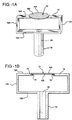
- specimen holder of the present invention having a pair of opposing support arms is illustrated in Figs. 1a and 1b.
- specimen 10 having first and second major surfaces 100 and 102 and peripheral edge 104, is seated on support arms 12.
- specimen 10 is in the form of a circular disk having a diameter of approximately 3 mm.
- the support arms are spaced so that they define a gap therebetween of less than the diameter of specimen 10.
- Support arms 12 are mounted on or otherwise secured to upstanding pedestal 18.
- pedestal 18 includes a bore 20 through its longitudinal axis to provide for the passage of a light beam as will be explained in further detail below.
- the pedestal and support arms may be fabricated from any suitable metal, preferably one which exhibits good heat conductivity and a low ion milling rate.
- each support arm 12 includes a first portion or segment 120 which extends generally laterally away from pedestal 18, a second upstanding portion or segment 122, and a third portion or segment 124 which extends generally laterally back toward the center axis of pedestal 18. In this manner, support arm 12 holds specimen 10 a predetermined spaced distance away from pedestal 18 but generally centered over bore 20.
- the particular configuration or number of the segments or portions of the support arms or arms is not critical. What is important is that the support arm is designed to position the specimen a spaced distance away from the pedestal to provide for line-of-sight clearance for the ion gun arrangement and to permit the ion beam or beams to impinge upon both sides of the specimen.
- Small recesses 14 are provided adjacent the tips of support arms 12 in portion 124.
- the recesses are of a depth slightly less than the typical thickness of a specimen 10 (e.g., 100-200 ⁇ m). Further, the recesses have a diameter slightly greater than the diameter of the specimen so that the specimen will seat in those recesses.
- specimen 10 is seated on support arms 12 using a wax compound 16.
- wax 16 is a relatively low melting point wax, preferably having a melting point less than about 150°C, and most preferably having a melting point in the range of from about 110°C to 140°C. Waxes having melting points in the lower end of the range are most preferred as less heating is required to soften or melt them.
- the use of a wax aids in heat transfer between specimen 10 and support arms 12 tp carry heat away from the specimen during milling and to reduce ion beam induced heat damage effects on the specimen.
- Specimen 10 is seated in recesses 14 as follows.
- the wax is blended with a volatile solvent such as, for example, acetone, and the blend is applied to the recesses 14.
- the solvent is permitted to evaporate; optionally, the specimen holder may be heated to aid in driving off the solvent.
- a specimen 10 is placed over the wax in alignment with recesses 14.
- the specimen holder is then reheated to cause the wax 16 to soften or melt, permitting specimen 10 to become seated in recesses 14.
- the wax is then cooled again, this time securing specimen 10 in position on the support arms 12.
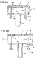
- FIGs. 2a and 2b, 4a, and 4b Mechanical securing means for securing specimen 10 to support arms 12 are illustrated in Figs. 2a and 2b, 4a, and 4b.
- specimen 10 is seated on support arms 12 in recesses 14.
- a clamping mechanism which includes a clamping surface 22, a clamping post 24, and a spring 26 holds the peripheral edges of specimen 10 in recesses 14.
- each clamping surface 22 extends over the upper peripheral edge of specimen 10 to secure the specimen in recesses 14.
- Clamping post 24 extends through first and third portions 120 and 124, respectively of support arm 12.
- One end of clamping post 24 is secured to clamping surface 22 while the opposite end includes a flange 106.
- spring 26 is captured.
- Spring 26 is sized to exert a clamping pressure on clamping surface 22. Further, springs 26 on either support arm 12 can be compressed to release clamping surface 22 for removal and insertion of different specimens as needed.
- FIG. 4a illustrates a screw 28 holding clamping surface 22 in position over specimen 10.
- pressure on clamping surface 22 can be released for insertion and/or removal of a specimen 10, and can be increased to secure the specimen in place.
- Fig. 4b illustrates yet another form of a mechanical clamping mechanism.
- C-shaped clamps 30 having clamping surfaces 22 are designed to snugly fit over support arms 12 to provide a clamping force on specimen 10.
- C-shaped clamps 10 may be slid on and off of support arms 12 to permit specimens to be insert or removed as required.
- specimen holder of the present invention may take the form of a pair of opposing support arms as shown in Figs. 1a, 1b, 2a, 2b, 4a, and 4b, in some instances, a single support arm 12 as shown in Fig. 3a may provide sufficient support to specimen 10 for an ion beam milling operation.
- a single support arm 12 as shown in Fig. 3a may provide sufficient support to specimen 10 for an ion beam milling operation.
- three or four support arm embodiments of the invention are also possible as shown in Figs. 3b and 3c, respectively.
- a particular advantage of the present invention is its flexibility of design for various applications and ion milling operations.
- the angles between support arms may be symmetrical or non-symmetrical as desired depending upon the configuration of the ion milling guns used to mill the specimens.
- the specimen holder of the present invention is quite suited for use in an ion beam milling system using modulated ion beams for sector ion milling. Such a system is commercially available from Gatan, Inc. of Pleasanton, CA.
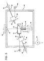
- FIG. 5 An example of an ion beam milling system using the specimen holder of the present invention is shown in Fig. 5.
- specimen 10 is supported by support arms 12 of the specimen holder in vacuum chamber 34.
- Suitable means such as a high vacuum pump 44 capable of reducing the pressure in chamber 34 to 10 -6 Torr, are used to evacuate the chamber.
- the pedestal 18 of the specimen holder is fitted onto a holder mount 32.
- Holder mount 32 may be rotated, by suitable rotary drive means (not shown), to cause specimen 10 to rotate during ion milling.
- Support arms 12 position specimen 10 so that it is generally centered over bore 20.
- a pair of ion guns 36 of substantially identical construction are connected to power supplies 52.
- one ion gun is positioned above the surface of specimen 10 and one is positioned below to direct an ion beam against the lower surface of specimen 10.
- a gas typically argon, is supplied to ion gun 36 through gas supply line 40, the supply of gas being regulated by valve 42.
- Ion gun 36 produces a beam of energetic particles which impinges onto specimen 10 through front aperture 38.
- the angle between the specimen surface (either upper or lower) and the ion beams being directed from either gun 36 may be adjusted to various values down to 0° for simultaneous milling of both surfaces.
- a light source 50 such as, for example a light emitting diode (LED), projects light generally vertically through pedestal bore 20. Milling may be terminated when the surface of specimen 10 is perforated or just prior to perforation when the surface of specimen 10 is sufficiently transparent so that the light from source 52 passes through specimen 10 and window 46 and impinges on a photodetector 48. Photodetector 48 may be connected through suitable circuitry (not shown) to terminate the power to ion guns 36 when it detects a predetermined threshold of light.
- LED light emitting diode
- Sector ion milling may be carried out by controlling power to the ion guns 36 such that power is supplied whenever the specimen holder is rotated to a position where there is line-of-sight clearance to the surface of specimen 10 and power is terminated whenever, due to rotation, support arms 12 enter the path of the ion beams. This reduces specimen contamination from sputtering of metal from either the support arms or the pedestal, reduces heat input, and provides high quality specimens for analysis.
Landscapes
- Chemical & Material Sciences (AREA)
- Analytical Chemistry (AREA)
- Physics & Mathematics (AREA)
- Health & Medical Sciences (AREA)
- Life Sciences & Earth Sciences (AREA)
- Biochemistry (AREA)
- General Health & Medical Sciences (AREA)
- General Physics & Mathematics (AREA)
- Immunology (AREA)
- Pathology (AREA)
- Sampling And Sample Adjustment (AREA)
Description
Claims (20)
- A specimen holder for two-sided ion beam milling comprising a pedestal (18) and means for securing a specimen (10) to said pedestal, characterized in that said pedestal (18) includes at least one extending specimen support arm (12) adapted to engage a peripheral edge (104) of a specimen (10) having first and second major surfaces (100, 102) such that at least a portion of said peripheral edge of said specimen remains unrestrained by said support arm and spaced from said pedestal, and means (16) for securing said specimen (10) to said at least one specimen support arm (12).
- A specimen holder as claimed in claim 1 including a plurality of specimen support arms (12) extending from said pedestal (18).
- A specimen holder as claimed in claim 1 in which said at least one specimen support arm (12) includes a recess (14) therein for engaging said peripheral edge (104) of said specimen (10), the depth of said recess being less than the height of said specimen.
- A specimen holder as claimed in claim 1 in which said securing means (16) comprises wax.
- A specimen holder as claimed in claim 4 in which said wax is a low melting point hydrocarbon wax.
- A specimen holder as claimed in claim 3 in which said securing means (16) comprises wax, and said wax is disposed in said recess (14).
- A specimen holder as claimed in claim 1 in which said securing means is a clamp (30).
- A specimen holder as claimed in claim 7 in which said clamp includes a clamping surface (22) for engaging said peripheral edge (104) of said specimen (10), a post (24) extending from said clamping surface, and a spring (26) on said post for biasing said clamping surface against said specimen support arm (12).
- A specimen holder as claimed in claim 1 in which said securing means comprises a clamping surface (20) for engaging said peripheral edge of said specimen and a screw (28) extending through said clamping surface for securing said clamping surface to said specimen support arm (12).
- A specimen holder as claimed in claim 1 in which said securing means comprises a C-shaped clamp (30) having a clamping surface (22) for engaging said peripheral edge (104) of said specimen and a base portion extending around and securing said clamp to said specimen support arm (12).
- A specimen holder as claimed in claim 1 in which said pedestal has a bore (20) therethrough.
- A specimen holder as claimed in claim 1 in which said at least one specimen support arm (12) includes a first portion (120) which extends laterally away from said pedestal, a second upstanding portion (122), and a third portion (124) extending laterally toward said pedestal (18).
- A specimen holder as claimed in claim 12 including a recess (14) in said third portion (124) of said at least one support arm (12) for engaging said peripheral edge (104) of said specimen, the depth of said recess being less than the height of said specimen (10).
- A specimen holder as claimed in claim 12 including a plurality of specimen support arms (12) extending from said pedestal (18).
- An apparatus for two-sided ion beam milling comprising a vacuum chamber (34) and means (44) for providing a vacuum within said chamber, a specimen holder within said chamber for holding a specimen (10) to be milled, and a plurality of ion guns (36) within said chamber, at least one of said guns positioned to provide an ion beam to a first side of said specimen and at least one other of said guns positioned to provide an ion beam to a second side of said specimen, said plurality of guns be adjustable to provide very low milling angles of incidence down to 0°, characterized in that said specimen holder comprises a pedestal (18) having at least one extending specimen support arm (12) adapted to engage a peripheral edge (104) of said specimen (10) such that at least a portion of said peripheral edge of said specimen remains unrestrained by said support arm and spaced from said pedestal, and means (16) for securing said specimen (10) to said at least one specimen support arm (12).
- An apparatus as claimed in claim 15 including a plurality of specimen support arms (12) extending from said pedestal (18).
- An apparatus as claimed in claim 15 in which said at least one specimen support arm (12) includes a recess (14) therein for engaging said peripheral edge (104) of said specimen, the depth of said recess being less than the height of said specimen.
- A method for the two-sided ion beam milling of specimens comprising the steps of providing a specimen (10) having first and second major surfaces (100, 102) and a peripheral edge (104) to be milled to a vacuum chamber and securing said specimen such that at least a portion of said peripheral edge remains unrestrained, evacuating said chamber to form a vacuum therein, and ion milling said specimen using a milling angle down to 0°, characterized in that the step of ion milling said specimen is carried out simultaneously on both major surfaces thereof.
- A method as claimed in claim 18 including the step of rotating said specimen during ion milling.
- A method as claimed in claim 18 wherein said specimen (10) is secured by a support holder having at least one extending specimen support arm (12) and wherein said ion milling is carried out by a plurality of ion guns (36), said method including the step of terminating power to said ion guns whenever said support arm is rotated into the path of ion beams emanating from said ion guns.
Applications Claiming Priority (3)
| Application Number | Priority Date | Filing Date | Title |
|---|---|---|---|
| US08/339,483 US5472566A (en) | 1994-11-14 | 1994-11-14 | Specimen holder and apparatus for two-sided ion milling system |
| US339483 | 1994-11-14 | ||
| PCT/US1995/013992 WO1996015436A1 (en) | 1994-11-14 | 1995-10-30 | Specimen holder and apparatus for two-sided ion milling system |
Publications (2)
| Publication Number | Publication Date |
|---|---|
| EP0792447A1 EP0792447A1 (en) | 1997-09-03 |
| EP0792447B1 true EP0792447B1 (en) | 1998-12-09 |
Family
ID=23329204
Family Applications (1)
| Application Number | Title | Priority Date | Filing Date |
|---|---|---|---|
| EP95938966A Expired - Lifetime EP0792447B1 (en) | 1994-11-14 | 1995-10-30 | Specimen holder and apparatus for two-sided ion milling system |
Country Status (5)
| Country | Link |
|---|---|
| US (1) | US5472566A (en) |
| EP (1) | EP0792447B1 (en) |
| JP (1) | JPH10508976A (en) |
| DE (1) | DE69506583T2 (en) |
| WO (1) | WO1996015436A1 (en) |
Cited By (1)
| Publication number | Priority date | Publication date | Assignee | Title |
|---|---|---|---|---|
| DE102005023894A1 (en) * | 2005-05-24 | 2006-12-28 | Logatec Gmbh | Articles e.g. electronic device such as monitor, transportation device for use on assembly line, has wedge-shaped base inserted and clamped in upper side piece of clamp transverse to transport direction of device designed as mounting plate |
Families Citing this family (39)
| Publication number | Priority date | Publication date | Assignee | Title |
|---|---|---|---|---|
| US5922179A (en) * | 1996-12-20 | 1999-07-13 | Gatan, Inc. | Apparatus for etching and coating sample specimens for microscopic analysis |
| US6106736A (en) * | 1997-09-04 | 2000-08-22 | International Business Machines Corporation | Planarization process and apparatus for the etch definition of magnetic head air bearing surfaces |
| JP2000035390A (en) * | 1998-07-16 | 2000-02-02 | Seiko Instruments Inc | Sectioning method |
| US6368664B1 (en) | 1999-05-03 | 2002-04-09 | Guardian Industries Corp. | Method of ion beam milling substrate prior to depositing diamond like carbon layer thereon |
| US6808606B2 (en) | 1999-05-03 | 2004-10-26 | Guardian Industries Corp. | Method of manufacturing window using ion beam milling of glass substrate(s) |
| US6768110B2 (en) | 2000-06-21 | 2004-07-27 | Gatan, Inc. | Ion beam milling system and method for electron microscopy specimen preparation |
| US6621081B2 (en) | 2001-01-10 | 2003-09-16 | International Business Machines Corporation | Method of pole tip sample preparation using FIB |
| US6680456B2 (en) | 2001-06-09 | 2004-01-20 | Honeywell International Inc. | Ion fusion formation |
| US7002152B2 (en) * | 2003-02-15 | 2006-02-21 | Bal-Tec Ag | Sample preparation for transmission electron microscopy |
| JP2005056535A (en) * | 2003-08-07 | 2005-03-03 | Tdk Corp | Method and device for manufacturing magnetic recording medium |
| KR100558196B1 (en) * | 2003-10-28 | 2006-03-10 | 삼성전자주식회사 | Mount for fixing the specimen for transmission electron microscopy and method for manufacturing the specimen using the same |
| JP2005322663A (en) * | 2004-05-06 | 2005-11-17 | Opnext Japan Inc | Semiconductor substrate polishing method and polishing jig |
| US7644637B2 (en) * | 2006-09-25 | 2010-01-12 | Omniprobe, Inc. | Method and apparatus for transfer of samples in a controlled environment |
| US8168960B2 (en) * | 2007-03-06 | 2012-05-01 | Leica Mikrosysteme Gmbh | Method for the production of a sample for electron microscopy |
| JP2009135078A (en) * | 2007-10-29 | 2009-06-18 | Tokyo Institute Of Technology | Sample holder for focused ion beam processing and focused ion beam apparatus |
| US8201813B2 (en) * | 2009-04-30 | 2012-06-19 | The United States Of America As Represented By The Secretary Of The Navy | Head window fixture and method |
| GB201002645D0 (en) * | 2010-02-17 | 2010-03-31 | Univ Lancaster | Method and apparatus for ion beam polishing |
| EP2545579B1 (en) * | 2010-03-08 | 2017-02-22 | Microscopy Innovations, LLC | Device for holding electron microscope grids and other materials |
| US8445874B2 (en) | 2010-04-11 | 2013-05-21 | Gatan Inc. | Ion beam sample preparation apparatus and methods |
| US8283642B2 (en) | 2010-04-11 | 2012-10-09 | Gatan, Inc. | Ion beam sample preparation apparatus and methods |
| US8653489B2 (en) | 2010-04-11 | 2014-02-18 | Gatan, Inc. | Ion beam sample preparation apparatus and methods |
| US8384050B2 (en) | 2010-04-11 | 2013-02-26 | Gatan, Inc. | Ion beam sample preparation thermal management apparatus and methods |
| JP2011232073A (en) * | 2010-04-26 | 2011-11-17 | Mitsubishi Heavy Ind Ltd | Observation sample preparation device |
| DE102010064462B3 (en) | 2010-07-30 | 2024-07-11 | Carl Zeiss Microscopy Gmbh | TEM lamella |
| DE102010032894B4 (en) * | 2010-07-30 | 2013-08-22 | Carl Zeiss Microscopy Gmbh | Tem lamella, process for its preparation and apparatus for carrying out the process |
| US8686379B1 (en) | 2010-09-07 | 2014-04-01 | Joseph C. Robinson | Method and apparatus for preparing serial planar cross sections |
| US8878147B2 (en) | 2010-09-07 | 2014-11-04 | Joseph C. Robinson | Method and apparatus for in situ preparation of serial planar surfaces for microscopy |
| DE102011111190A1 (en) | 2011-08-25 | 2013-02-28 | Fraunhofer-Gesellschaft zur Förderung der angewandten Forschung e.V. | Method and device for preparing a sample for microstructural diagnostics |
| KR101335064B1 (en) * | 2011-11-30 | 2013-12-03 | 강원대학교산학협력단 | Ion Milling Specimen Holder |
| US8791438B2 (en) | 2012-07-27 | 2014-07-29 | Gatan Inc. | Ion beam sample preparation apparatus and methods |
| US10110854B2 (en) | 2012-07-27 | 2018-10-23 | Gatan, Inc. | Ion beam sample preparation apparatus and methods |
| CN105082003B (en) * | 2014-05-21 | 2017-03-29 | 华东理工大学 | A kind of clamp method of micro-test sample clamping device |
| EP3153838B1 (en) * | 2015-10-06 | 2022-07-06 | Fraunhofer-Gesellschaft zur Förderung der angewandten Forschung e.V. | Method for preparing a sample for the microstructure diagnosis and sample for micro structure diagnosis |
| DE102017130797B4 (en) * | 2017-12-20 | 2022-06-09 | Leibniz-Institut für Oberflächenmodifizierung e.V. | Process for creating a desired surface profile |
| KR101998719B1 (en) * | 2017-12-22 | 2019-07-10 | 주식회사 포스코 | Sample processing apparatus |
| CN110006927B (en) * | 2019-03-21 | 2021-02-12 | 浙江大学 | Device for preparing high-strength high-conductivity copper alloy in-situ tensile sample and using method thereof |
| US20230420216A1 (en) * | 2022-05-19 | 2023-12-28 | Fei Company | Combined laser and broad ion beam (bib) systems for more efficient processing of multiple samples |
| EP4283277A1 (en) * | 2022-05-24 | 2023-11-29 | Leica Mikrosysteme GmbH | Sample holder, loading device, and method for inserting a sample into a sample holder |
| US20250308837A1 (en) * | 2024-03-26 | 2025-10-02 | Fei Company | Airless transfer and electrical testing of solid state batteries in scanning electron microscopes |
Family Cites Families (8)
| Publication number | Priority date | Publication date | Assignee | Title |
|---|---|---|---|---|
| FR2203509A5 (en) * | 1972-10-16 | 1974-05-10 | Anvar | |
| US4128765A (en) * | 1976-10-29 | 1978-12-05 | Joseph Franks | Ion beam machining techniques and apparatus |
| DE3211022A1 (en) * | 1981-03-31 | 1982-11-11 | Ion Tech Ltd., Teddington, Middlesex | METHOD AND DEVICE FOR PROVIDING A SAMPLE SUITABLE FOR EXAMINATION WITH AN ELECTRONIC MICROSCOPE |
| US4411733A (en) * | 1982-06-18 | 1983-10-25 | Bell Telephone Laboratories, Incorporated | SPER Device for material working |
| HU190855B (en) * | 1983-10-12 | 1986-11-28 | Mta Mueszaki Fizikai Kutato Intezete,Hu | Device for working solid samples by ion beam and ion source to the device |
| US5009743A (en) * | 1989-11-06 | 1991-04-23 | Gatan Incorporated | Chemically-assisted ion beam milling system for the preparation of transmission electron microscope specimens |
| JP2886649B2 (en) * | 1990-09-27 | 1999-04-26 | 株式会社日立製作所 | Ion beam processing method and apparatus |
| JPH06207891A (en) * | 1993-01-11 | 1994-07-26 | Matsushita Electron Corp | Sample base for ion milling apparatus |
-
1994
- 1994-11-14 US US08/339,483 patent/US5472566A/en not_active Expired - Lifetime
-
1995
- 1995-10-30 EP EP95938966A patent/EP0792447B1/en not_active Expired - Lifetime
- 1995-10-30 WO PCT/US1995/013992 patent/WO1996015436A1/en not_active Ceased
- 1995-10-30 DE DE69506583T patent/DE69506583T2/en not_active Expired - Lifetime
- 1995-10-30 JP JP8516090A patent/JPH10508976A/en active Pending
Cited By (1)
| Publication number | Priority date | Publication date | Assignee | Title |
|---|---|---|---|---|
| DE102005023894A1 (en) * | 2005-05-24 | 2006-12-28 | Logatec Gmbh | Articles e.g. electronic device such as monitor, transportation device for use on assembly line, has wedge-shaped base inserted and clamped in upper side piece of clamp transverse to transport direction of device designed as mounting plate |
Also Published As
| Publication number | Publication date |
|---|---|
| DE69506583D1 (en) | 1999-01-21 |
| EP0792447A1 (en) | 1997-09-03 |
| DE69506583T2 (en) | 1999-07-29 |
| JPH10508976A (en) | 1998-09-02 |
| US5472566A (en) | 1995-12-05 |
| WO1996015436A1 (en) | 1996-05-23 |
Similar Documents
| Publication | Publication Date | Title |
|---|---|---|
| US5472566A (en) | Specimen holder and apparatus for two-sided ion milling system | |
| US6914244B2 (en) | Ion beam milling system and method for electron microscopy specimen preparation | |
| US6188068B1 (en) | Methods of examining a specimen and of preparing a specimen for transmission microscopic examination | |
| US7002152B2 (en) | Sample preparation for transmission electron microscopy | |
| US6300631B1 (en) | Method of thinning an electron transparent thin film membrane on a TEM grid using a focused ion beam | |
| US6417512B1 (en) | Sample distortion removing method in thin piece forming | |
| EP1998356B1 (en) | In-Situ STEM Sample Preparation | |
| US5009743A (en) | Chemically-assisted ion beam milling system for the preparation of transmission electron microscope specimens | |
| JP3892360B2 (en) | Ion beam equipment | |
| US20040262515A1 (en) | Information acquisition apparatus, cross section evaluating apparatus, and cross section evaluating method | |
| JP3711018B2 (en) | TEM sample thinning method | |
| JP4170048B2 (en) | Ion beam apparatus and ion beam processing method | |
| EP3023763B1 (en) | Specimen preparation device | |
| Poppa et al. | Experimental approaches to well controlled studies of thin-film nucleation and growth | |
| CN121049313B (en) | Non-positioning and extraction-free method for integrating FIB preparation and TKD characterization | |
| Fischione | Materials specimen preparation for transmission electron microscopy | |
| Barna et al. | Simple method for the preparation of InP based samples for TEM investigation | |
| EP4528783A1 (en) | Sample carrier and uses thereof | |
| CN112397365B (en) | Sample table suitable for TIC3X three-ion-beam cutting instrument | |
| WO2026047412A1 (en) | Converged ion beam polishing system using radio frequency based gridded ion source and applications thereof | |
| Richmond | XPS analysis of the sapphire surface as a function of high temperature vacuum annealing | |
| CN113547468A (en) | Pre-tilted sample holder and sample processing method | |
| Alani et al. | An Updated Gas Source Focused Ion Beam Instrument for TEM Specimen Preparation | |
| JPH09164489A (en) | Ion beam processing equipment | |
| Alani et al. | A New ion Beam Based Etching/Coating System for Scanning Electron Microscopy (SEM) and Light Microscopy (LM) |
Legal Events
| Date | Code | Title | Description |
|---|---|---|---|
| PUAI | Public reference made under article 153(3) epc to a published international application that has entered the european phase |
Free format text: ORIGINAL CODE: 0009012 |
|
| 17P | Request for examination filed |
Effective date: 19970324 |
|
| AK | Designated contracting states |
Kind code of ref document: A1 Designated state(s): DE FR GB |
|
| GRAG | Despatch of communication of intention to grant |
Free format text: ORIGINAL CODE: EPIDOS AGRA |
|
| 17Q | First examination report despatched |
Effective date: 19970919 |
|
| GRAG | Despatch of communication of intention to grant |
Free format text: ORIGINAL CODE: EPIDOS AGRA |
|
| GRAH | Despatch of communication of intention to grant a patent |
Free format text: ORIGINAL CODE: EPIDOS IGRA |
|
| GRAH | Despatch of communication of intention to grant a patent |
Free format text: ORIGINAL CODE: EPIDOS IGRA |
|
| GRAA | (expected) grant |
Free format text: ORIGINAL CODE: 0009210 |
|
| AK | Designated contracting states |
Kind code of ref document: B1 Designated state(s): DE FR GB |
|
| REF | Corresponds to: |
Ref document number: 69506583 Country of ref document: DE Date of ref document: 19990121 |
|
| ET | Fr: translation filed | ||
| PLBE | No opposition filed within time limit |
Free format text: ORIGINAL CODE: 0009261 |
|
| STAA | Information on the status of an ep patent application or granted ep patent |
Free format text: STATUS: NO OPPOSITION FILED WITHIN TIME LIMIT |
|
| 26N | No opposition filed | ||
| REG | Reference to a national code |
Ref country code: GB Ref legal event code: IF02 |
|
| PGFP | Annual fee paid to national office [announced via postgrant information from national office to epo] |
Ref country code: FR Payment date: 20021002 Year of fee payment: 8 |
|
| PG25 | Lapsed in a contracting state [announced via postgrant information from national office to epo] |
Ref country code: FR Free format text: LAPSE BECAUSE OF NON-PAYMENT OF DUE FEES Effective date: 20040630 |
|
| REG | Reference to a national code |
Ref country code: FR Ref legal event code: ST |
|
| REG | Reference to a national code |
Ref country code: DE Ref legal event code: R082 Ref document number: 69506583 Country of ref document: DE Representative=s name: MEHLER ACHLER PATENTANWAELTE, DE |
|
| PGFP | Annual fee paid to national office [announced via postgrant information from national office to epo] |
Ref country code: DE Payment date: 20141023 Year of fee payment: 20 Ref country code: GB Payment date: 20141029 Year of fee payment: 20 |
|
| REG | Reference to a national code |
Ref country code: DE Ref legal event code: R071 Ref document number: 69506583 Country of ref document: DE |
|
| REG | Reference to a national code |
Ref country code: GB Ref legal event code: PE20 Expiry date: 20151029 |
|
| PG25 | Lapsed in a contracting state [announced via postgrant information from national office to epo] |
Ref country code: GB Free format text: LAPSE BECAUSE OF EXPIRATION OF PROTECTION Effective date: 20151029 |