EP0791804B1 - Angular velocity sensor - Google Patents
Angular velocity sensor Download PDFInfo
- Publication number
- EP0791804B1 EP0791804B1 EP96929545A EP96929545A EP0791804B1 EP 0791804 B1 EP0791804 B1 EP 0791804B1 EP 96929545 A EP96929545 A EP 96929545A EP 96929545 A EP96929545 A EP 96929545A EP 0791804 B1 EP0791804 B1 EP 0791804B1
- Authority
- EP
- European Patent Office
- Prior art keywords
- tuning fork
- driving
- electrode
- angular velocity
- electrodes
- Prior art date
- Legal status (The legal status is an assumption and is not a legal conclusion. Google has not performed a legal analysis and makes no representation as to the accuracy of the status listed.)
- Expired - Lifetime
Links
Images






Classifications
-
- G—PHYSICS
- G01—MEASURING; TESTING
- G01C—MEASURING DISTANCES, LEVELS OR BEARINGS; SURVEYING; NAVIGATION; GYROSCOPIC INSTRUMENTS; PHOTOGRAMMETRY OR VIDEOGRAMMETRY
- G01C19/00—Gyroscopes; Turn-sensitive devices using vibrating masses; Turn-sensitive devices without moving masses; Measuring angular rate using gyroscopic effects
- G01C19/56—Turn-sensitive devices using vibrating masses, e.g. vibratory angular rate sensors based on Coriolis forces
- G01C19/5607—Turn-sensitive devices using vibrating masses, e.g. vibratory angular rate sensors based on Coriolis forces using vibrating tuning forks
Definitions
- the present invention relates to a vibration type angular velocity sensor for use in the attitude control, navigation, etc. of mobile items such as aircrafts, automobiles, robots, ships, vehicles, or an angular velocity sensor for use in the anti-blurring gear, remote controller etc. of still cameras, video cameras.
- An angular velocity sensor of the above category comprises a U-shape vibration member, on which piezoelectric elements are attached each forming a driving section and a detecting section.
- the tuning fork arm of piezoelectric element is driven by a driving power source supplied to electrode of piezoelectric element of said vibration member, and the Coriolis force generated at the detecting section is detected as an angular velocity signal to be taken out of the piezoelectric element of detecting section.
- a signal taken out of the detection electrode contains, besides the angular velocity signal, unnecessary signals induced by the driving signal. Therefore, it needs a circuit to separate the unnecessary signal.
- a problem is that the signals other than angular velocity signal are not thoroughly separated by the circuit; part of which remains as noise, making it difficult to improve the detection characteristics.
- the present invention is intended to eliminate the influence due to noise from driving signal, thereby improving the detection characteristics of angular velocity signal.
- an angular velocity sensor comprises U-shape first and second piezoelectric elements bonded together sandwiching a detection electrode, said first piezoelectric element having in at least one of the tuning fork arms a first and a second driving electrode on a surface opposite to the detection electrode and said second piezoelectric element having in a tuning fork arm corresponding to the tuning fork arm on which said first and second driving electrodes are disposed a third and a fourth driving electrode on a surface opposite to the detection electrode; wherein, among said first through fourth driving electrodes, the first and the third driving electrodes disposed in diagonal arrangement across the detection electrode are coupled with a first driving power source while the second and the fourth driving electrodes disposed on another diagonal line across the detection electrode are coupled with a second driving power source which supplies a signal whose phase is inverse to that of said first driving power source, and at least one of the tuning fork arms of said U-shape first and second piezoelectric elements is polarized in a direction of thickness along
- the first and the third driving electrodes disposed in a diagonal arrangement in a tuning fork arm receive a driving signal from the first driving power source, while the second and the fourth driving electrodes disposed on another diagonal line in the tuning fork arm receive a driving signal from the second driving power source the phase of which signal being inverse to that of the first driving power source.
- the signals for driving the tuning fork arm are thus applied across a detection electrode, which means that the driving signals cancel each other on the detection electrode, never mixed in a detection signal. As a result, the capability of detecting the angular velocity signal is improved.
- an angular velocity sensor comprises U-shape first and second piezoelectric elements bonded together sandwiching an intermediate electrode, said first piezoelectric element having in at least one of the tuning fork arms a first and a second driving electrode and a first detection electrode on a surface opposite to the intermediate electrode and said second piezoelectric element having in a tuning fork arm corresponding to the tuning fork arm on which said first and second driving electrodes and first detection electrode are disposed a third and a fourth driving electrodes and a second detection electrode on a surface opposite to the intermediate electrode; wherein, among said first, second, third and fourth driving electrodes, the first and the third driving electrodes disposed in diagonal arrangement across the intermediate electrode are coupled with a first driving power source while the second and the fourth driving electrodes disposed on another diagonal line across the intermediate electrode are coupled with a second driving power source which supplies a signal whose phase is inverse to that of said first driving power source, and at least one of the tuning fork arms of said U-shape first and second pie
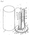
- Fig.1 is a perspective view showing an assembled angular velocity sensor according to a first embodiment of the present invention.
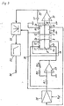
- Fig.2 is a conceptual chart showing the key portion of the angular velocity sensor of Fig.1.
- Fig.3 is a circuit diagram of the angular velocity sensor of Fig.1.
- Fig.4 is a conceptual chart showing the key portion of other example of the angular velocity sensor.
- Fig.5 is a perspective view showing an assembled angular sensor according to a second embodiment of the present invention.
- Fig.6 is a conceptual chart showing the key portion of the angular velocity sensor of Fig.5.
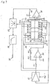
- Fig.7 is a circuit diagram of the angular velocity sensor of Fig.5.
- Fig.8 is a conceptual chart showing the key portion of other example of the angular velocity sensor.
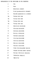
- FIG. 1 denotes an iron cap with the bottom open, nickel plated on the surface, the bottom opening is fitted with a disk base 2 to form a sealed space within cap 1 housing an assembled angular velocity sensor.
- a detection element 3 is disposed within the sealed space without having contact with the inner surface of cap 1, the detection element being fixed on the base 2 with glue.
- Said detection element 3 is comprised of U-shape first and second piezoelectric elements 4,5, bonded together with a U-shape Ag-Pd detection electrode 6 in between, sintered to form a single body, as shown in Fig.1.
- oblong shaped Ag-Pd electrodes 7,8,9,10,11,12,13 and 14 are provided respectively by printing/sintering, as shown in Fig.1 and Fig.2.
- 7,8,11 and 12 being driving electrodes
- 9,10,13 and 14 being monitor electrodes.
- driving electrodes 7,12 disposed on a diagonal across the detection electrode 6 are coupled with a first driving power source 15, while driving electrodes 8,11 disposed on another diagonal line crossing said diagonal are coupled with a second driving power source 16.
- Each of the first and second driving power sources 15, 16 supplies AC signal(tuning fork resonance frequency) to the pair of driving electrodes 7,12 and the other pair of driving electrodes 8,11, respectively, to make the tuning fork resonate.
- the signals supplied from the first and the second driving power sources 15,16 are inverse-phased to each other.
- monitor electrodes 9,14 disposed on a diagonal are grounded, while monitor electrodes 10,13 disposed on another diagonal crossing said diagonal line are connected to a monitor detection terminal 17.
- Detection electrode 6 is connected to detection terminal 18.
- Fig.1 where, 19,20 are power supply terminals connected by lead wires A.
- the lead wire A between detection terminal 18 and detection electrode 6 is connected with the detection electrode 6 at a location lower than the tuning fork arms 4a,4b,5a,5b.
- the tuning fork arm 4a,5a is polarized for 3kV/mm field intensity in the direction of thickness, while the tuning fork arm 4b,5b is polarized opposite in the direction of thickness for 3kV/mm field intensity, as shown in Fig.2.
- Directions of the polarization are indicated with the symbols P1 and P2, respectively.
- the tuning fork arm 4a,5a vibrates sidewise to the polarization direction P1
- the tuning fork arm 4b,5b resonates to make sidewise vibration to the polarization direction P2.
- the driving electrode 8 is provided with a negative electric field while the driving electrode 12 is provided with a positive electric field; this means that both of the tuning fork arms 4a and 5a are provided with a negative electric field towards the bottom in Fig.2, viz. in the opposite side to the polarization direction P1, and the inner side of tuning fork arm 4a,5a shrinks.
- an electric field of the same direction as the polarization direction P1 is provided from the driving electrodes 7,11 causing an elongation.
- the tuning fork arm 4a,5a bends inward, viz.
- the tuning fork arm 4b,5b corresponds to the move of tuning fork arm 4a,5a bending towards the tuning fork arm 4a,5a.
- the tuning fork arm 4a,5a and tuning fork arm 4b,5b are respectively bent outward. These actions are alternated and the U-shape vibration member makes a resonating vibration.
- the driving electrodes 7,8 are elongated in a direction which is the direction of polarization, at the same time is perpendicular to the polarization direction, to generate a positive electric charge; the driving electrodes 11,12 are shrunken in a direction which is opposite to the polarization, at the same time is perpendicular to the polarization direction, to generate a positive electric charge as well.
- Signals for driving tuning fork arms 4a,5a,4b,5b are supplied to the tuning fork arms 4a,5a,4b,5b. However, their signal components cancel each other and the driving signal is never mixed in a detection signal detectable by detection electrode 6.
- Fig.3 shows the circuit diagram.
- the detection terminal 18 is connected to a reversal input terminal of a charge amplifier comprised of an amplifier 21 and a capacitor C1.
- An output terminal 27 of said charge amplifier is connected to a synchronous detection circuit 22, a filter 23, and ultimately to an output terminal 24.
- a reversal amplifier comprised of resistors R1,R2, a variable resistor Rx and an amplifier 25 is for forming the first and the second driving power sources 15,16.
- Numeral 26 represents an AGC amplifier for stabilizing the amplitude of tuning fork.
- Fig.4 shows another example of an angular velocity sensor according to the first embodiment of the present invention; where, the polarization direction P3 of tuning fork arm 4b,5b is changed to be the same as P1.
- the detection electrode is unable to pick up a sum of Coriolis signal components of tuning fork arms 4a,5a and 4b,5b, which was performed in the embodiment of Fig.2. Therefore, each of Coriolis signals generated in detection electrodes 18a and 18b is picked up individually, and then added together after reversing signal component of a Coriolis signal derived from either one of the tuning fork arms, to obtain a detection signal.
- At least one of the tuning fork arms of U-shape first and second piezoelectric elements bonded together is polarized in a direction of thickness along which the piezoelectric elements are bonded, the first and the third driving electrodes disposed on a diagonal of tuning fork arm are supplied with a driving signal from a first driving power source while the second and the fourth driving electrodes are supplied with a driving signal from a second driving power source whose phase is inverse to that of the first driving power source.
- the signal components for driving a tuning fork arm function to drive the tuning fork, but they cancel each other, and the driving signal is never mixed in a detection signal to be detected by the detection electrode.
- the capability of detecting an angular velocity is improved to a higher accuracy level.
- the signals generated in detection electrodes 18a and 18b may be picked up individually, and then these signal components may be added together after reversing a signal component derived from either one of the tuning fork arms, to an improved capability for detecting an angular velocity.
- Fig.5, Fig.6 and Fig.7 show an angular velocity sensor according to a second embodiment of the present invention.
- numeral 1 denotes an iron cap with the bottom open, nickel-plated on the surface, the bottom opening is fitted to a disk base 2 to form a sealed space within cap 1 housing an assembled angular velocity sensor.
- a detection element 3 is disposed within the sealed space without having contact with the inner surface of cap 1, the detection element being fixed on the base 2 with glue.
- Said detection element 3 is comprised of U-shape first and second piezoelectric elements 4,5 bonded together with a U-shape Ag-Pd intermediate electrode 36 in between, sintered to form a single body, as shown in Fig.5.
- oblong shaped Ag-Pd electrodes 37,38,39,40,41,42,43,44,45,46,47 and 48 are provided respectively by printing/ sintering.
- these electrodes 37,39,43 and 45 being driving electrodes
- 40,42,46 and 48 being monitor electrodes.
- driving electrodes 37, 45 disposed on a diagonal across the intermediate electrode 36 are coupled with a first driving power source 15, while driving electrodes 39,43 disposed on another diagonal line crossing said diagonal are coupled with a second driving power source 16.
- Each of the first and second driving power sources 15, 16 supplies AC signal(tuning fork resonance frequency) to the pair of driving electrodes 37,45 and the other pair of driving electrodes 39,43, respectively, to make the tuning fork resonate.
- the signals supplied from the first and the second driving power sources 15,16 are inverse-phased to each other.
- monitor electrodes 40,48 disposed on a diagonal are grounded, while monitor electrodes 42,46 disposed on other diagonal line crossing said diagonal are connected to a monitor detection terminal 51.
- Intermediate electrode 36 is connected to a ground terminal 52.
- Detection electrodes 38,41 are connected to a detection terminal 55a, and detection electrodes 44,47 are connected to a detection terminal 55b.
- Fig.5 where, 53,54 are power supply terminals connected by lead wires A.
- the lead wire A between ground terminal 52 and intermediate electrode 36 is connected to the intermediate electrode 36 at a location lower than the tuning fork arms 4a,4b,5a,5b.
- the tuning fork arm 4a,5a is polarized for 3kV/mm field intensity in the direction of thickness, while the tuning fork arm 4b,5b is polarized opposite to the direction of thickness for 3kV/mm field intensity, as shown in in Fig.6.
- the polarization directions are indicated with the symbols P1 and P2, respectively.
- the tuning fork arm 4a,5a vibrates sidewise to the polarization direction P1
- the tuning fork arm 4b,5b resonates to make sidewise vibration to the polarization direction P2.
- the inner driving electrodes 39,45 of the tuning fork arm 4a,5a are supplied with signals of inverse phase
- the driving electrode 39 is provided with a negative electric field while the driving electrode 45 is provided with a positive electric field; this means that both of the tuning fork arms 4a and 5a are provided with a negative electric field towards the bottom in Fig.6, viz.
- tuning fork arm 4a,5a bends inward, viz. tilts towards the tuning fork arm 4b,5b.
- the tuning fork arm 4b,5b moves corresponding to the move of tuning fork arm 4a,5a and bends towards the tuning fork arm 4a,5a.
- the tuning fork arm 4a,5a and tuning fork arm 4b,5b are respectively bent outward. These actions are alternated and the U-shape vibration member makes a resonation vibration.
- the driving electrode 38 is elongated in a direction which is the direction of polarization, at the same time is perpendicular to the polarization direction, to generate a positive electric charge
- the detection electrode 44 is shrunken in a direction which is opposite to the polarization direction, at the same time is perpendicular to the polarization direction, to generate a positive electric charge as well.
- a negative electric charge is generated in a portion of detection electrode 36 sandwiched by tuning fork arms 4a,5a, which is taken out from detection terminal 55.
- the driving electrode 44 of tuning fork arm 4a,5a is elongated, while the detection electrode 38 is shrunken; and a negative electric charge is taken out from detection terminal 55.
- a positive or a negative electric charge is generated also at the tuning fork arm 4b,5b to be taken out from detection terminal 55.
- Signals for driving tuning fork arms 4a,5a,4b,5b are supplied to the tuning fork arms 4a,5a,4b,5b. However, their signal components cancel each other.
- the driving signals are grounded through intermediate electrode 36, the detection sector being separated from the driving sector, therefore the driving signal is never mixed in the detection sector.
- Fig.7 shows the circuit diagram thereof.
- the detection terminal 55 is connected to a reversal input terminal of a charge amplifier comprised of an amplifier 56 and a capacitor C1.
- An output terminal 62 of said charge amplifier is connected to a synchronous detection circuit 57, a filter 58, and ultimately to an output terminal 59.
- An reversal amplifier comprised of resistors R1,R2, a variable resistor Rx and an amplifier 60 is for forming the first and the second driving power sources 15,16.
- Numeral 61 represents an AGC amplifier for stabilizing the amplitude of tuning fork.
- Fig.8 shows another example of an angular velocity sensor according to the second embodiment of the present invention; where, the polarization direction P3 of tuning fork arm 4b,5b is changed to be the same as P1.
- each of Coriolis signals generated in the right and the left tuning fork arms is picked up individually by detection electrodes 38,44 and detection electrodes 41,47. Namely, the sum of signal components 55a derived from detection electrodes 38,44 and the sum of signal components 55b derived from detection electrodes 41,47 are picked up separately, and then added together after reversing the signal component 55a derived from one of the tuning fork arms, to obtain a detection signal.
- an angular velocity sensor comprises U-shape first and second piezoelectric elements bonded together sandwiching an intermediate electrode, a first and a second driving electrodes and a first detection electrode provided on the surface of at least one of the tuning fork arms of the first piezoelectric element, and a third and a fourth driving electrode and a second detection electrode provided on the surface of the tuning fork arm of second piezoelectric element; where, among the first, second, third and fourth driving electrodes, the first and the third driving electrodes disposed on a diagonal across the intermediate electrode are supplied with driving signal from the first driving power source, the second and the fourth driving electrodes disposed on a diagonal across the intermediate electrode are supplied with driving signal from the second driving power supply source the phase of which is inverse to that of the first driving power supply source, at least one of the tuning fork arms of U-shape first and second piezoelectric elements bonded together is polarized in a direction of thickness along which the piezoelectric elements are
- the signal components for driving a tuning fork arm function to drive the tuning fork, they are never mixed in a detection signal, because the detection sector is completely separated from the driving sector. As a result, the capability of detecting angular velocity is improved to a higher accuracy.
- the signals generated in detection electrodes 38,44 and detection electrodes 41,47 may be picked up individually and then these signal components may be added together after reversing a signal component derived from either one of the tuning fork arms, to the improvement in the capability of detecting angular velocity.
- the noise components which appear due to unwanted vibration component when a tuning fork arm is at work can be significantly reduced.
- an angular velocity sensor In an angular velocity sensor according to the present invention, although the signal components for driving a tuning fork arm function to drive the tuning fork they are never mixed in a detection signal via the electrode, because the detection sector is completely separated from the driving sector. As a result, the capability of detecting angular velocity is improved to a higher accuracy.
Landscapes
- Physics & Mathematics (AREA)
- Engineering & Computer Science (AREA)
- General Physics & Mathematics (AREA)
- Radar, Positioning & Navigation (AREA)
- Remote Sensing (AREA)
- Gyroscopes (AREA)
Abstract
Description
- The present invention relates to a vibration type angular velocity sensor for use in the attitude control, navigation, etc. of mobile items such as aircrafts, automobiles, robots, ships, vehicles, or an angular velocity sensor for use in the anti-blurring gear, remote controller etc. of still cameras, video cameras.
- An angular velocity sensor of the above category comprises a U-shape vibration member, on which piezoelectric elements are attached each forming a driving section and a detecting section. The tuning fork arm of piezoelectric element is driven by a driving power source supplied to electrode of piezoelectric element of said vibration member, and the Coriolis force generated at the detecting section is detected as an angular velocity signal to be taken out of the piezoelectric element of detecting section.
- In the above described structure, however, a signal taken out of the detection electrode contains, besides the angular velocity signal, unnecessary signals induced by the driving signal. Therefore, it needs a circuit to separate the unnecessary signal. A problem is that the signals other than angular velocity signal are not thoroughly separated by the circuit; part of which remains as noise, making it difficult to improve the detection characteristics.
- The present invention is intended to eliminate the influence due to noise from driving signal, thereby improving the detection characteristics of angular velocity signal.
- In order to implement the objective, an angular velocity sensor according to the present invention comprises U-shape first and second piezoelectric elements bonded together sandwiching a detection electrode, said first piezoelectric element having in at least one of the tuning fork arms a first and a second driving electrode on a surface opposite to the detection electrode and said second piezoelectric element having in a tuning fork arm corresponding to the tuning fork arm on which said first and second driving electrodes are disposed a third and a fourth driving electrode on a surface opposite to the detection electrode; wherein, among said first through fourth driving electrodes, the first and the third driving electrodes disposed in diagonal arrangement across the detection electrode are coupled with a first driving power source while the second and the fourth driving electrodes disposed on another diagonal line across the detection electrode are coupled with a second driving power source which supplies a signal whose phase is inverse to that of said first driving power source, and at least one of the tuning fork arms of said U-shape first and second piezoelectric elements is polarized in a direction of thickness along which the first and the second piezoelectric elements are bonded together.
- Under the above described constitution, the first and the third driving electrodes disposed in a diagonal arrangement in a tuning fork arm receive a driving signal from the first driving power source, while the second and the fourth driving electrodes disposed on another diagonal line in the tuning fork arm receive a driving signal from the second driving power source the phase of which signal being inverse to that of the first driving power source. The signals for driving the tuning fork arm are thus applied across a detection electrode, which means that the driving signals cancel each other on the detection electrode, never mixed in a detection signal. As a result, the capability of detecting the angular velocity signal is improved.
- Further, an angular velocity sensor according to the present invention comprises U-shape first and second piezoelectric elements bonded together sandwiching an intermediate electrode, said first piezoelectric element having in at least one of the tuning fork arms a first and a second driving electrode and a first detection electrode on a surface opposite to the intermediate electrode and said second piezoelectric element having in a tuning fork arm corresponding to the tuning fork arm on which said first and second driving electrodes and first detection electrode are disposed a third and a fourth driving electrodes and a second detection electrode on a surface opposite to the intermediate electrode; wherein, among said first, second, third and fourth driving electrodes, the first and the third driving electrodes disposed in diagonal arrangement across the intermediate electrode are coupled with a first driving power source while the second and the fourth driving electrodes disposed on another diagonal line across the intermediate electrode are coupled with a second driving power source which supplies a signal whose phase is inverse to that of said first driving power source, and at least one of the tuning fork arms of said U-shape first and second piezoelectric elements is polarized in a direction of thickness along which the first and the second piezoelectric elements are bonded together.
- Under the above described constitution, the influence due to noise from driving signal is eliminated and the characteristics of detecting angular velocity signal are raised.
- Fig.1 is a perspective view showing an assembled angular velocity sensor according to a first embodiment of the present invention. Fig.2 is a conceptual chart showing the key portion of the angular velocity sensor of Fig.1. Fig.3 is a circuit diagram of the angular velocity sensor of Fig.1. Fig.4 is a conceptual chart showing the key portion of other example of the angular velocity sensor. Fig.5 is a perspective view showing an assembled angular sensor according to a second embodiment of the present invention. Fig.6 is a conceptual chart showing the key portion of the angular velocity sensor of Fig.5. Fig.7 is a circuit diagram of the angular velocity sensor of Fig.5. Fig.8 is a conceptual chart showing the key portion of other example of the angular velocity sensor.
- In the following, an angular velocity sensor according to an embodiment of the present invention is described referring to drawings. In Fig.1,
numeral 1 denotes an iron cap with the bottom open, nickel plated on the surface, the bottom opening is fitted with adisk base 2 to form a sealed space withincap 1 housing an assembled angular velocity sensor. Adetection element 3 is disposed within the sealed space without having contact with the inner surface ofcap 1, the detection element being fixed on thebase 2 with glue. Saiddetection element 3 is comprised of U-shape first and secondpiezoelectric elements Pd detection electrode 6 in between, sintered to form a single body, as shown in Fig.1. On the surface oftuning fork arms piezoelectric elements Pd electrodes tuning fork arm electrodes detection electrode 6 are coupled with a firstdriving power source 15, while drivingelectrodes driving power source 16. Each of the first and seconddriving power sources driving electrodes electrodes driving power sources - In a
tuning fork arm monitor electrodes monitor electrodes monitor detection terminal 17.Detection electrode 6 is connected todetection terminal 18. These electrical connections are illustrated in Fig.1, where, 19,20 are power supply terminals connected by lead wires A. The lead wire A betweendetection terminal 18 anddetection electrode 6 is connected with thedetection electrode 6 at a location lower than thetuning fork arms - With the above described constitution, the
tuning fork arm tuning fork arm - When driving
electrodes driving power sources tuning fork arm tuning fork arm - Explaining more in detail, suppose the
inner driving electrodes tuning fork arm electrode 8 is provided with a negative electric field while the drivingelectrode 12 is provided with a positive electric field; this means that both of thetuning fork arms tuning fork arm tuning fork arm driving electrodes tuning fork arm tuning fork arm tuning fork arm tuning fork arm tuning fork arm driving power sources tuning fork arm tuning fork arm - When an angular velocity is applied to the U-shape vibration member being in resonance vibration the
tuning fork arm tuning fork arm detection electrode 6 anddetection terminal 18. For example, referring to Fig.2, when thetuning fork arm tuning fork arm 4a elongates while the upper surface oftuning fork arm 5a shrinks, thedriving electrodes driving electrodes detection electrode 6 sandwiched by tuningfork arms detection electrode 6 sandwiched by tuning forkarms detection terminal 18. When an angular velocity of opposite direction is applied to, the drivingelectrodes tuning fork arm electrodes detection terminal 18 by the same principle as described above. - Signals for driving tuning fork
arms tuning fork arms detection electrode 6. - Fig.3 shows the circuit diagram. The
detection terminal 18 is connected to a reversal input terminal of a charge amplifier comprised of anamplifier 21 and a capacitor C1. Anoutput terminal 27 of said charge amplifier is connected to asynchronous detection circuit 22, afilter 23, and ultimately to anoutput terminal 24. A reversal amplifier comprised of resistors R1,R2, a variable resistor Rx and anamplifier 25 is for forming the first and the seconddriving power sources Numeral 26 represents an AGC amplifier for stabilizing the amplitude of tuning fork. - Fig.4 shows another example of an angular velocity sensor according to the first embodiment of the present invention; where, the polarization direction P3 of
tuning fork arm arms detection electrodes - As described in the above, in an angular velocity sensor according to a first embodiment of the present invention, at least one of the tuning fork arms of U-shape first and second piezoelectric elements bonded together is polarized in a direction of thickness along which the piezoelectric elements are bonded, the first and the third driving electrodes disposed on a diagonal of tuning fork arm are supplied with a driving signal from a first driving power source while the second and the fourth driving electrodes are supplied with a driving signal from a second driving power source whose phase is inverse to that of the first driving power source. With the above constitution, the signal components for driving a tuning fork arm function to drive the tuning fork, but they cancel each other, and the driving signal is never mixed in a detection signal to be detected by the detection electrode. As a result, the capability of detecting an angular velocity is improved to a higher accuracy level.
- By making the polarization direction of the right and the left tuning fork arms opposite to each other, Coriolis forces derived from the right and the left arms assume a same phase as a signal on the detection electrode, and the summing is conducted on the detection electrode, resulting in the elimination of a summing circuit. Thus, the whole structure is remarkably simplified.
- When the right and the left tuning fork arms are made to have a same direction of polarization, the signals generated in
detection electrodes - Furthermore, by polarizing only the portion corresponding to electrodes provided in the driving sector and the detection sector, noise components which appear due to unwanted vibration component while a tuning fork arm is at work can be significantly reduced.
- Fig.5, Fig.6 and Fig.7 show an angular velocity sensor according to a second embodiment of the present invention. In Fig.5,
numeral 1 denotes an iron cap with the bottom open, nickel-plated on the surface, the bottom opening is fitted to adisk base 2 to form a sealed space withincap 1 housing an assembled angular velocity sensor. Adetection element 3 is disposed within the sealed space without having contact with the inner surface ofcap 1, the detection element being fixed on thebase 2 with glue. Saiddetection element 3 is comprised of U-shape first and secondpiezoelectric elements intermediate electrode 36 in between, sintered to form a single body, as shown in Fig.5. On the surface oftuning fork arms piezoelectric elements Pd electrodes tuning fork arm electrodes intermediate electrode 36 are coupled with a firstdriving power source 15, while drivingelectrodes driving power source 16. Each of the first and second drivingpower sources electrodes electrodes driving power sources - In a
tuning fork arm electrodes monitor electrodes monitor detection terminal 51.Intermediate electrode 36 is connected to aground terminal 52.Detection electrodes detection terminal 55a, anddetection electrodes detection terminal 55b. These electrical connections are shown in Fig.5, where, 53,54 are power supply terminals connected by lead wires A. The lead wire A betweenground terminal 52 andintermediate electrode 36 is connected to theintermediate electrode 36 at a location lower than thetuning fork arms - With the above described constitution, the
tuning fork arm tuning fork arm - When driving
electrodes power sources tuning fork arm tuning fork arm inner driving electrodes tuning fork arm electrode 39 is provided with a negative electric field while the drivingelectrode 45 is provided with a positive electric field; this means that both of thetuning fork arms tuning fork tuning fork arm electrodes tuning fork arm tuning fork arm tuning fork arm tuning fork arm tuning fork arm driving power sources tuning fork arm tuning fork arm - When an angular velocity is applied to the U-shape vibration member being in the resonance vibration the
tuning fork arm tuning fork arm detection electrodes detection terminal 55. - For example, referring to Fig.6, when the
tuning fork arm tuning fork arm 4a elongates while the upper surface oftuning fork arm 5a shrinks, the drivingelectrode 38 is elongated in a direction which is the direction of polarization, at the same time is perpendicular to the polarization direction, to generate a positive electric charge;
thedetection electrode 44 is shrunken in a direction which is opposite to the polarization direction, at the same time is perpendicular to the polarization direction, to generate a positive electric charge as well. When, a negative electric charge is generated in a portion ofdetection electrode 36 sandwiched by tuningfork arms detection terminal 55. When an angular velocity of opposite direction is applied to, the drivingelectrode 44 oftuning fork arm detection electrode 38 is shrunken; and a negative electric charge is taken out fromdetection terminal 55. By the same principle, a positive or a negative electric charge is generated also at thetuning fork arm detection terminal 55. - Signals for driving
tuning fork arms tuning fork arms intermediate electrode 36, the detection sector being separated from the driving sector, therefore the driving signal is never mixed in the detection sector. - Fig.7 shows the circuit diagram thereof. The
detection terminal 55 is connected to a reversal input terminal of a charge amplifier comprised of anamplifier 56 and a capacitor C1. Anoutput terminal 62 of said charge amplifier is connected to asynchronous detection circuit 57, afilter 58, and ultimately to anoutput terminal 59. An reversal amplifier comprised of resistors R1,R2, a variable resistor Rx and anamplifier 60 is for forming the first and the seconddriving power sources Numeral 61 represents an AGC amplifier for stabilizing the amplitude of tuning fork. - Fig.8 shows another example of an angular velocity sensor according to the second embodiment of the present invention; where, the polarization direction P3 of
tuning fork arm - In this case, as Coriolis signal components of
tuning fork arms detection electrodes detection electrodes signal components 55a derived fromdetection electrodes signal components 55b derived fromdetection electrodes signal component 55a derived from one of the tuning fork arms, to obtain a detection signal. - As described in the above, an angular velocity sensor according to the second embodiment of the present invention comprises U-shape first and second piezoelectric elements bonded together sandwiching an intermediate electrode, a first and a second driving electrodes and a first detection electrode provided on the surface of at least one of the tuning fork arms of the first piezoelectric element, and a third and a fourth driving electrode and a second detection electrode provided on the surface of the tuning fork arm of second piezoelectric element; where, among the first, second, third and fourth driving electrodes, the first and the third driving electrodes disposed on a diagonal across the intermediate electrode are supplied with driving signal from the first driving power source, the second and the fourth driving electrodes disposed on a diagonal across the intermediate electrode are supplied with driving signal from the second driving power supply source the phase of which is inverse to that of the first driving power supply source, at least one of the tuning fork arms of U-shape first and second piezoelectric elements bonded together is polarized in a direction of thickness along which the piezoelectric elements are bonded. In the above described structure, although the signal components for driving a tuning fork arm function to drive the tuning fork, they are never mixed in a detection signal, because the detection sector is completely separated from the driving sector. As a result, the capability of detecting angular velocity is improved to a higher accuracy.
- By making the polarization direction of the right and the left tuning fork arms opposite to each other, Coriolis forces derived from the right and the left arms assume a same phase as a signal on detection electrode, and the summing is conducted on detection electrode resulting in the elimination of a summing circuit. Thus, the whole structure is remarkably simplified.
- When the right and the left tuning fork arms are made to have a same direction of polarization, the signals generated in
detection electrodes detection electrodes - Furthermore, by polarizing only the portion corresponding to electrodes provided in the driving sector and the detection sector, the noise components which appear due to unwanted vibration component when a tuning fork arm is at work can be significantly reduced.
- In an angular velocity sensor according to the present invention, although the signal components for driving a tuning fork arm function to drive the tuning fork they are never mixed in a detection signal via the electrode, because the detection sector is completely separated from the driving sector. As a result, the capability of detecting angular velocity is improved to a higher accuracy.
Claims (10)
- An angular velocity sensor comprising
U-shape first and second piezoelectric elements (4,5) bonded together sandwiching a detection electrode (6), and forming a single body having a tuning fork shape, said first piezoelectric element (4) having in at least one of the tuning fork arms (4a,b) a first and a second driving electrode (7,8) on a surface opposite to the detection electrode (6) and said second piezoelectric element (5) having in a tuning fork arm (5a) corresponding to the tuning fork arm (4a) on which said first and second driving electrodes (7,8) are disposed a third and a fourth driving electrode (12,11) on a surface opposite to the detection electrode (6); wherein
the first and the third driving electrodes (7,12), among said first through fourth driving electrodes (7,8,12,11), disposed in diagonal arrangement across the detection electrode (6), are coupled with a first driving power source (15), while the second and the fourth driving electrodes (8,11) disposed in diagonal arrangement across the detection electrode (6) are coupled with a second driving power source (16) which supplies a signal whose phase is inverse to that of said first driving power source (15), and at least one of the tuning fork arms (4a,4b,5a,5b) of said U-shape first and second piezoelectric elements (4,5) is polarized in a direction of thickness along which the first and the second piezoelectric elements (4,5) are bonded together. - The angular velocity sensor of Claim 1, further comprising monitor electrodes (9,10,14,13) of a same arrangement as the driving electrodes (7,8,12,11) provided in the other tuning fork arm of the first and the second piezoelectric elements (4,5), wherein
the right and the left tuning fork arms are polarized in a direction opposite to each other. - The angular velocity sensor of Claim 2, wherein only a portion corresponding to the driving electrode and the monitor electrode is polarized.
- The angular velocity sensor of Claim 1, further comprising monitor electrodes (9,10,14,13) of a same arrangement as the driving electrodes provided in the other tuning fork arm of the first and the second piezoelectric elements (4,5), wherein
the right and the left tuning fork arms are polarized in a same direction. - The angular velocity sensor of Claim 4, wherein only a portion corresponding to the driving electrode and the monitor electrode is polarized.
- An angular velocity sensor comprising U-shape first and second piezoelectric elements (4,5) bonded together sandwiching an intermediate electrode (36), and forming a single body having a tuning fork shape, said first piezoelectric element (4a) having in at least one of the tuning fork arms a first and a second driving electrode (37,39) and a first detection electrode (38) on a surface opposite to the intermediate electrode (36) and said second piezoelectric element (5a) having in a tuning fork arm corresponding to the tuning fork arm on which said first and second driving electrodes (37,39) and first detection electrode (38) are disposed a third and a fourth driving electrode (45,43) and a second detection electrode (44) on a surface opposite to the intermediate electrode (36); wherein
the first and the third driving electrodes (37,45), among said first, second, third and fourth driving electrodes (37,39,45,43), disposed in diagonal arrangement across the intermediate electrode (36), are coupled with a first driving power source (15), while the second and the fourth driving electrodes (39,43) disposed in diagonal arrangement across the intermediate electrode (36) are coupled with a second driving power source (16) which supplies a signal whose phase is inverse to that of said first driving power source (15), and at least one of the tuning fork arms of said U-shape first and second piezoelectric elements (4,5) is polarized in a direction of thickness along which the first and the second piezoelectric elements (4,5) are bonded together. - The angular velocity sensor of Claim 6, further comprising monitor electrodes (40,42,48,46) and a detection electrode (41,47) of a same arrangement as the driving electrodes (37,39,45,43) and detection electrode (38,44) on one tuning fork arm provided in the other tuning fork arm, wherein
the right and the left tuning fork arms are polarized in a direction opposite to each other. - The angular velocity sensor of Claim 7, wherein only a portion corresponding to the driving electrode, the detection electrode and the monitor electrode is polarized.
- The angular velocity sensor of Claim 6, further comprising monitor electrodes (40,42,48,46) and a detection electrode (41,47) of a same arrangement as the driving electrodes (37,39,45,43) and detection electrode (38,44) on one tuning fork arm provided in the other tuning fork arm of the first and the second piezoelectric elements, wherein
the right and the left tuning fork arms are polarized in the same direction. - The angular velocity sensor of Claim 9, wherein only a portion corresponding to the driving electrode, the detection electrode and the monitor electrode is polarized.
Applications Claiming Priority (7)
| Application Number | Priority Date | Filing Date | Title |
|---|---|---|---|
| JP230885/95 | 1995-09-08 | ||
| JP23088595 | 1995-09-08 | ||
| JP23088595A JP3360500B2 (en) | 1995-09-08 | 1995-09-08 | Angular velocity sensor |
| JP33000295 | 1995-12-19 | ||
| JP330002/95 | 1995-12-19 | ||
| JP33000295A JP3360510B2 (en) | 1995-12-19 | 1995-12-19 | Angular velocity sensor |
| PCT/JP1996/002538 WO1997009585A1 (en) | 1995-09-08 | 1996-09-06 | Angular velocity sensor |
Publications (3)
| Publication Number | Publication Date |
|---|---|
| EP0791804A1 EP0791804A1 (en) | 1997-08-27 |
| EP0791804A4 EP0791804A4 (en) | 1999-11-17 |
| EP0791804B1 true EP0791804B1 (en) | 2004-11-24 |
Family
ID=26529593
Family Applications (1)
| Application Number | Title | Priority Date | Filing Date |
|---|---|---|---|
| EP96929545A Expired - Lifetime EP0791804B1 (en) | 1995-09-08 | 1996-09-06 | Angular velocity sensor |
Country Status (4)
| Country | Link |
|---|---|
| US (1) | US5854427A (en) |
| EP (1) | EP0791804B1 (en) |
| DE (1) | DE69633909T2 (en) |
| WO (1) | WO1997009585A1 (en) |
Families Citing this family (22)
| Publication number | Priority date | Publication date | Assignee | Title |
|---|---|---|---|---|
| JP3369033B2 (en) * | 1995-08-31 | 2003-01-20 | アルプス電気株式会社 | Vibratory gyroscope |
| JP3739492B2 (en) * | 1996-02-21 | 2006-01-25 | 富士通株式会社 | Tuning fork type piezoelectric vibration gyro |
| US6437483B2 (en) | 1996-11-26 | 2002-08-20 | Ngk Insulators, Ltd. | Vibrator, vibratory gyroscope, and vibration adjusting method |
| US6018212A (en) | 1996-11-26 | 2000-01-25 | Ngk Insulators, Ltd. | Vibrator, vibratory gyroscope, and vibration adjusting method |
| US5998911A (en) * | 1996-11-26 | 1999-12-07 | Ngk Insulators, Ltd. | Vibrator, vibratory gyroscope, and vibration adjusting method |
| US6747393B2 (en) | 1996-11-26 | 2004-06-08 | Ngk Insulators, Ltd. | Vibrator, vibratory gyroscope, and vibration adjusting method |
| JP3336451B2 (en) * | 1997-08-22 | 2002-10-21 | 富士通株式会社 | Tuning fork type vibration gyro |
| JPH1194554A (en) * | 1997-09-17 | 1999-04-09 | Fujitsu Ltd | Tuning fork type piezoelectric vibration gyro |
| JP3335122B2 (en) * | 1998-05-06 | 2002-10-15 | 松下電器産業株式会社 | Angular velocity sensor |
| US6457358B1 (en) | 1999-03-18 | 2002-10-01 | Board Of Regents Of The University Of Nebraska | Tubular coriolis force driven piezoelectric gyroscope system, and method of use |
| US6140748A (en) * | 1999-03-18 | 2000-10-31 | Board Of Regents Of The University Of Nebraska | High voltage sensitivity coriolis force driven peizoelectric transformer-gryoscope system, and method of use |
| US6777857B1 (en) | 1999-03-18 | 2004-08-17 | Board Of Regents Of The University Of Nebraska | Piezoelectric gyroscope system, and method of use |
| WO2001036910A1 (en) * | 1999-11-16 | 2001-05-25 | Matsushita Electric Industrial Co., Ltd. | Angular speed sensor |
| JP4449128B2 (en) * | 1999-12-14 | 2010-04-14 | パナソニック株式会社 | Angular velocity sensor |
| US6666091B2 (en) * | 2000-08-30 | 2003-12-23 | Matsushita Electric Industrial Co., Ltd. | Angular velocity sensor |
| US6858972B2 (en) * | 2002-06-21 | 2005-02-22 | Ngk Insulators, Ltd. | Vibrator, vibratory gyroscope, and vibration adjusting method |
| JPWO2005080919A1 (en) * | 2004-02-20 | 2007-10-25 | 松下電器産業株式会社 | Angular velocity sensor |
| JP2008076222A (en) * | 2006-09-21 | 2008-04-03 | Fujitsu Ltd | Tuning fork type vibration gyro sensor |
| JP4990717B2 (en) * | 2007-08-10 | 2012-08-01 | セイコーインスツル株式会社 | Case manufacturing method, piezoelectric vibrator, oscillator, electronic device, and radio timepiece |
| JP5128262B2 (en) * | 2007-12-17 | 2013-01-23 | セイコーインスツル株式会社 | Piezoelectric vibrating piece, piezoelectric vibrator, oscillator, electronic device, radio timepiece, and method of manufacturing piezoelectric vibrating piece |
| JP4636093B2 (en) * | 2008-02-20 | 2011-02-23 | セイコーエプソン株式会社 | Vibrating piece, vibrator, oscillator, and vibrating piece manufacturing method |
| JP5560806B2 (en) * | 2010-03-19 | 2014-07-30 | セイコーエプソン株式会社 | Gyro element, gyro sensor, and electronic device |
Family Cites Families (7)
| Publication number | Priority date | Publication date | Assignee | Title |
|---|---|---|---|---|
| JPS62217115A (en) * | 1986-03-19 | 1987-09-24 | Tokyo Keiki Co Ltd | Gyro device |
| JPS6358111A (en) * | 1986-08-27 | 1988-03-12 | Japan Storage Battery Co Ltd | Tuning fork type piezo-electric angular velocity sensor |
| US5430342A (en) * | 1993-04-27 | 1995-07-04 | Watson Industries, Inc. | Single bar type vibrating element angular rate sensor system |
| JP2780643B2 (en) * | 1994-06-03 | 1998-07-30 | 株式会社村田製作所 | Vibrating gyro |
| JPH0894362A (en) * | 1994-09-20 | 1996-04-12 | Yoshiro Tomikawa | Oscillatory gyroscope |
| JPH08128833A (en) * | 1994-10-28 | 1996-05-21 | Yoshiro Tomikawa | Vibration-type gyroscope |
| JP3439861B2 (en) * | 1995-01-25 | 2003-08-25 | アルプス電気株式会社 | Vibratory gyroscope |
-
1996
- 1996-09-06 DE DE69633909T patent/DE69633909T2/en not_active Expired - Lifetime
- 1996-09-06 EP EP96929545A patent/EP0791804B1/en not_active Expired - Lifetime
- 1996-09-06 WO PCT/JP1996/002538 patent/WO1997009585A1/en not_active Ceased
- 1996-09-06 US US08/836,482 patent/US5854427A/en not_active Expired - Lifetime
Also Published As
| Publication number | Publication date |
|---|---|
| WO1997009585A1 (en) | 1997-03-13 |
| US5854427A (en) | 1998-12-29 |
| DE69633909T2 (en) | 2005-11-24 |
| EP0791804A1 (en) | 1997-08-27 |
| EP0791804A4 (en) | 1999-11-17 |
| DE69633909D1 (en) | 2004-12-30 |
Similar Documents
| Publication | Publication Date | Title |
|---|---|---|
| US5854427A (en) | Angular velocity sensor | |
| KR100288070B1 (en) | Vibratory gyroscope | |
| EP0764828A1 (en) | Angular velocity sensor | |
| EP1314962A1 (en) | Angular velocity sensor | |
| JP4590853B2 (en) | Rotation rate sensor and multi-axis detection type rotation rate sensor | |
| JP4449128B2 (en) | Angular velocity sensor | |
| US7234352B2 (en) | Angular velocity senor | |
| JPH09126783A (en) | Piezoelectric vibration gyro | |
| US6907783B2 (en) | Vibrating gyroscope and angular velocity sensor | |
| EP0744593A2 (en) | Vibrating gyroscope | |
| US6028390A (en) | Piezoelectric resonator and electronic component including same | |
| US6564639B1 (en) | Angular speed sensor | |
| JP3360510B2 (en) | Angular velocity sensor | |
| JPH0972744A (en) | Angular velocity sensor | |
| JP3360491B2 (en) | Angular velocity sensor | |
| JP3075262B2 (en) | Tuning fork type piezoelectric gyro sensor | |
| JPH07218270A (en) | Vehicle motion detection device and detection sensitivity adjustment method thereof | |
| JPH0914967A (en) | Vibrating type gyroscope | |
| JPH09105633A (en) | Angular velocity sensor | |
| US6634230B2 (en) | Vibrating gyroscope and electronic unit using the same | |
| JP6205953B2 (en) | Electronic devices, electronic devices, and moving objects | |
| JPH07159177A (en) | Piezoelectric vibration gyroscope device | |
| JP2909851B2 (en) | Piezoelectric vibration gyro | |
| JP2536151B2 (en) | Vibrating gyro | |
| JPH05264281A (en) | Piezoelectric vibration gyro |
Legal Events
| Date | Code | Title | Description |
|---|---|---|---|
| PUAI | Public reference made under article 153(3) epc to a published international application that has entered the european phase |
Free format text: ORIGINAL CODE: 0009012 |
|
| 17P | Request for examination filed |
Effective date: 19970429 |
|
| AK | Designated contracting states |
Kind code of ref document: A1 Designated state(s): DE FR GB |
|
| A4 | Supplementary search report drawn up and despatched |
Effective date: 19991005 |
|
| AK | Designated contracting states |
Kind code of ref document: A4 Designated state(s): DE FR GB |
|
| GRAP | Despatch of communication of intention to grant a patent |
Free format text: ORIGINAL CODE: EPIDOSNIGR1 |
|
| GRAS | Grant fee paid |
Free format text: ORIGINAL CODE: EPIDOSNIGR3 |
|
| GRAA | (expected) grant |
Free format text: ORIGINAL CODE: 0009210 |
|
| AK | Designated contracting states |
Kind code of ref document: B1 Designated state(s): DE FR GB |
|
| REG | Reference to a national code |
Ref country code: GB Ref legal event code: FG4D |
|
| REF | Corresponds to: |
Ref document number: 69633909 Country of ref document: DE Date of ref document: 20041230 Kind code of ref document: P |
|
| ET | Fr: translation filed | ||
| PLBE | No opposition filed within time limit |
Free format text: ORIGINAL CODE: 0009261 |
|
| STAA | Information on the status of an ep patent application or granted ep patent |
Free format text: STATUS: NO OPPOSITION FILED WITHIN TIME LIMIT |
|
| 26N | No opposition filed |
Effective date: 20050825 |
|
| REG | Reference to a national code |
Ref country code: GB Ref legal event code: 746 Effective date: 20091215 |
|
| PGFP | Annual fee paid to national office [announced via postgrant information from national office to epo] |
Ref country code: GB Payment date: 20120905 Year of fee payment: 17 |
|
| PGFP | Annual fee paid to national office [announced via postgrant information from national office to epo] |
Ref country code: DE Payment date: 20120829 Year of fee payment: 17 Ref country code: FR Payment date: 20120926 Year of fee payment: 17 |
|
| GBPC | Gb: european patent ceased through non-payment of renewal fee |
Effective date: 20130906 |
|
| REG | Reference to a national code |
Ref country code: DE Ref legal event code: R119 Ref document number: 69633909 Country of ref document: DE Effective date: 20140401 |
|
| REG | Reference to a national code |
Ref country code: FR Ref legal event code: ST Effective date: 20140530 |
|
| PG25 | Lapsed in a contracting state [announced via postgrant information from national office to epo] |
Ref country code: GB Free format text: LAPSE BECAUSE OF NON-PAYMENT OF DUE FEES Effective date: 20130906 |
|
| PG25 | Lapsed in a contracting state [announced via postgrant information from national office to epo] |
Ref country code: DE Free format text: LAPSE BECAUSE OF NON-PAYMENT OF DUE FEES Effective date: 20140401 Ref country code: FR Free format text: LAPSE BECAUSE OF NON-PAYMENT OF DUE FEES Effective date: 20130930 |