EP0790797B1 - Dispenser with flow control - Google Patents
Dispenser with flow control Download PDFInfo
- Publication number
- EP0790797B1 EP0790797B1 EP95936397A EP95936397A EP0790797B1 EP 0790797 B1 EP0790797 B1 EP 0790797B1 EP 95936397 A EP95936397 A EP 95936397A EP 95936397 A EP95936397 A EP 95936397A EP 0790797 B1 EP0790797 B1 EP 0790797B1
- Authority
- EP
- European Patent Office
- Prior art keywords
- liquid
- dispenser
- flow
- reservoir
- container
- Prior art date
- Legal status (The legal status is an assumption and is not a legal conclusion. Google has not performed a legal analysis and makes no representation as to the accuracy of the status listed.)
- Expired - Lifetime
Links
Images

Classifications
-
- B—PERFORMING OPERATIONS; TRANSPORTING
- B67—OPENING, CLOSING OR CLEANING BOTTLES, JARS OR SIMILAR CONTAINERS; LIQUID HANDLING
- B67D—DISPENSING, DELIVERING OR TRANSFERRING LIQUIDS, NOT OTHERWISE PROVIDED FOR
- B67D7/00—Apparatus or devices for transferring liquids from bulk storage containers or reservoirs into vehicles or into portable containers, e.g. for retail sale purposes
- B67D7/02—Apparatus or devices for transferring liquids from bulk storage containers or reservoirs into vehicles or into portable containers, e.g. for retail sale purposes for transferring liquids other than fuel or lubricants
- B67D7/0216—Apparatus or devices for transferring liquids from bulk storage containers or reservoirs into vehicles or into portable containers, e.g. for retail sale purposes for transferring liquids other than fuel or lubricants by squeezing collapsible or flexible storage containers
- B67D7/0222—Apparatus or devices for transferring liquids from bulk storage containers or reservoirs into vehicles or into portable containers, e.g. for retail sale purposes for transferring liquids other than fuel or lubricants by squeezing collapsible or flexible storage containers the dispensed quantity of liquid being replaced by air sucked through the dispensing opening
-
- A—HUMAN NECESSITIES
- A47—FURNITURE; DOMESTIC ARTICLES OR APPLIANCES; COFFEE MILLS; SPICE MILLS; SUCTION CLEANERS IN GENERAL
- A47K—SANITARY EQUIPMENT; ACCESSORIES THEREFOR, e.g. TOILET ACCESSORIES
- A47K5/00—Holders or dispensers for soap, toothpaste or the like
- A47K5/06—Dispensers for soap
- A47K5/12—Dispensers for soap for liquid or pasty soap
- A47K5/122—Dispensers for soap for liquid or pasty soap using squeeze bottles or the like
-
- B—PERFORMING OPERATIONS; TRANSPORTING
- B65—CONVEYING; PACKING; STORING; HANDLING THIN OR FILAMENTARY MATERIAL
- B65D—CONTAINERS FOR STORAGE OR TRANSPORT OF ARTICLES OR MATERIALS, e.g. BAGS, BARRELS, BOTTLES, BOXES, CANS, CARTONS, CRATES, DRUMS, JARS, TANKS, HOPPERS, FORWARDING CONTAINERS; ACCESSORIES, CLOSURES, OR FITTINGS THEREFOR; PACKAGING ELEMENTS; PACKAGES
- B65D47/00—Closures with filling and discharging, or with discharging, devices
- B65D47/04—Closures with discharging devices other than pumps
- B65D47/20—Closures with discharging devices other than pumps comprising hand-operated members for controlling discharge
- B65D47/2018—Closures with discharging devices other than pumps comprising hand-operated members for controlling discharge comprising a valve or like element which is opened or closed by deformation of the container or closure
-
- B—PERFORMING OPERATIONS; TRANSPORTING
- B67—OPENING, CLOSING OR CLEANING BOTTLES, JARS OR SIMILAR CONTAINERS; LIQUID HANDLING
- B67D—DISPENSING, DELIVERING OR TRANSFERRING LIQUIDS, NOT OTHERWISE PROVIDED FOR
- B67D1/00—Apparatus or devices for dispensing beverages on draught
- B67D1/0001—Apparatus or devices for dispensing beverages on draught by squeezing collapsible or flexible storage containers
-
- G—PHYSICS
- G01—MEASURING; TESTING
- G01F—MEASURING VOLUME, VOLUME FLOW, MASS FLOW OR LIQUID LEVEL; METERING BY VOLUME
- G01F11/00—Apparatus requiring external operation adapted at each repeated and identical operation to measure and separate a predetermined volume of fluid or fluent solid material from a supply or container, without regard to weight, and to deliver it
- G01F11/02—Apparatus requiring external operation adapted at each repeated and identical operation to measure and separate a predetermined volume of fluid or fluent solid material from a supply or container, without regard to weight, and to deliver it with measuring chambers which expand or contract during measurement
- G01F11/08—Apparatus requiring external operation adapted at each repeated and identical operation to measure and separate a predetermined volume of fluid or fluent solid material from a supply or container, without regard to weight, and to deliver it with measuring chambers which expand or contract during measurement of the diaphragm or bellows type
- G01F11/082—Apparatus requiring external operation adapted at each repeated and identical operation to measure and separate a predetermined volume of fluid or fluent solid material from a supply or container, without regard to weight, and to deliver it with measuring chambers which expand or contract during measurement of the diaphragm or bellows type of the squeeze container type
Definitions
- This invention relates to dispensers for liquids and more particularly to dispensers capable of storing and dispensing medium to higher viscosity products such as shampoo, hand soap and the like.
- Dispensers have been developed which consist of an inverted container for receiving the liquid and having a bottom outlet positioned inside a reservoir. A pool of the liquid accumulates under atmospheric pressure in the reservoir around the bottom outlet to thereby trap the liquid in the container with a negative pressure above the liquid. Various structures have been provided to disturb the balance of the liquid and the negative pressure in the container to thereby cause controlled flow from the dispenser through an outlet associated with the reservoir. Such dispensers can be seen in applicant's prior patents, namely U.S. Patents 4324349, 4635828, 4645097, 5033653, and 5217147.
- U.S. Patent 5033653 which includes diagrams illustrating the the conflicting parameters associated with providing temperature compensation.
- the liquid must not flow from the dispenser when temperature rises, and yet the dispenser must have a response rate which will allow the user to dispense almost instantaneously upon applying a force to the dispenser.
- U.S. Patent 5033653 also provides structures which overcome these disadvantages satisfactorily by separating the two parameters so that response rate will not be so dependent on the amount of temperature compensation provided in the structure.
- liquids of higher viscosities are used, there is a disadvantage in all of the prior structures which was not apparent earlier.
- a second cause of the same difficulty results from the rate of recovery of the dispenser after squeezing the container to dispense.
- the initial force driving the recovery rate is greatest when the container is at its maximum deflection where the most energy is available to drive the recovery.
- air will initially be inspired into the dispenser at a high rate and this will cause the air to tunnel through the liquid and into the container.
- Dispensers of the present type include a flow path through which liquid must pass to leave the dispenser. After the dispenser is actuated to dispense, the flow path then receives reverse flow as the dispenser recovers ready for the next dispensing. This is an inherent and desirable part of dispensers of the present type because this reverse flow limits the possibility of dripping from the dispensing outlet.
- the present invention places a flow controller in the flow path which automatically adjusts to have little or no interference with the flow of liquid leaving the dispenser and then positions itself to slow down the rate of reverse flow into the dispenser. This slowing down of the rate ensures that the energy which would otherwise be available for sudden recovery, is available to drive the viscous liquid through a restricted path.
- the invention provides a dispenser for liquids of the type having a resilient container for containing the liquid to be dispensed and an outlet structure for containing a pool of the liquid at ambient air pressure to support the liquid in the container with a zone of negative pressure above the liquid, the dispenser being operated by deforming the container to cause liquid to flow outwardly along the flow path and to cause flow inwardly upon relaxing the container to discontinue dispensing, the dispenser being characterized by a flow controller positioned in the flow path and operable automatically in response to movement of liquid outwardly along the flow path to move the flow controller into a first condition in which the controller exhibits minimal resistance to flow, and then in response to movement of liquid inwardly along the flow path to move the flow controller into a second condition in which the controller exhibits increased resistance to flow sufficient to reduce the natural rate of flow into the container.
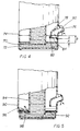
- Fig. 1 shows an exemplary dispenser 20 according to one of the preferred embodiments of the invention.
- the dispenser includes a resilient, deformable container 22 holding a supply of liquid 24 and having an inverted bottom outlet 26 in a neck 28.
- a flow controller 30 is immersed in a pool of liquid 32 which maintains a zone 33 of negative pressure above the liquid 24.
- the pool is contained in an outlet structure 31 having a reservoir 34 which is attached by threaded engagement 36 to a suitably formed portion of the container 22.
- a pivoted closure element 38 (shown in a closed position) blocks a discharge opening 40 and can be moved into an open position 42 (shown in ghost outline) for storage when the dispenser is in use.
- the operation of the dispenser is similar to that described in the aforementioned patents.
- the negative pressure in the zone 33 above the liquid 24 retains the column of liquid in the container because the liquid can not inspire air to displace the liquid due to the fact that the neck 28 of the container meets the pool of liquid 32 in the reservoir 34.
- liquid can be made to leave the dispenser. This is conveniently done by making the container 22 sufficiently flexible and resilient that the user can squeeze it thereby changing the pressure balance and causing liquid to flow downwardly past the flow controller 30 (which will be described later) and into the reservoir. The level in the reservoir will rise until such time as the level meets the discharge opening 40 and the liquid will leave the dispenser.
- the arrangement also provides space for volumetric change of the zone 33 caused by ambient temperature fluctuations.
- the flow controller 30 is added to the structure to minimize the likelihood of air tunnelling through the liquid.
- the flow controller shown in Fig. 1 consists of an anchor ring 44 which is a push fit inside the bottle neck. Attached to the anchor ring to the left of Fig. 1 is a flap 46 connected at a living hinge 48. There is minimal strength in the hinge so that as a result, under normal circumstances the flap will tend to fall into a first condition or open position 50 (shown in ghost outline). In this position the flow controller offers minimal resistance to flow out of the container, and through the reservoir to the discharge opening 40. On the other hand, as soon as the user stops dispensing, the energy stored in the walls of the container 22 will be at a maximum and provide maximum force to draw liquid and air back into the container 22. Because the flow is reversed, the flap will automatically take up a second condition or closed position shown in Fig. 1 and the only access to the container is then through a central opening 52 in the flap.
- the pressure drop across the opening 52 in the controller is such that the energy available to draw air into the container through the discharge opening 40 is reduced.
- the rate of flow is therefore reduced relative to the natural flow without the flow controller and the air has little chance to drive its way through the liquid. Consequently the level of liquid in the reservoir 34 will drop slowly as liquid is drawn through the opening 52 in the flow controller flap 46. This will result in the pool of liquid 32 in the dispenser returning essentially to the position shown in Fig. 1 where it was before dispensing took place. Of course the level of liquid in the container 22 will have dropped.
- the flow controller 30 is lying in a flow path through which liquid must flow as it travels from the container and passes through the reservoir and issues through the discharge opening. The effect of this is an increase in the resistance to liquid flow when the flow is reversed.
- Fig. 2 illustrates an alternative form of flow controller which differs only in that instead of having a central opening 52, the flap is waisted to define access openings 54, 56 to either side of a short living hinge 58.
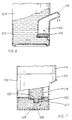
- flow controller can be used such as that shown in Fig. 3.
- the flow controller is illustrated in sections and is made up of first and second parts 60, 62 which are located and attached to one another to contain a free ball 64 (shown in the reverse flow position).
- the part 60 defines a conical opening which closes upwardly and terminates in several radial ribs 66 defining between the ribs space for flow past the ball.
- the second (or lower part 62) has four radial fingers 68 (three of which can be seen) which support the ball and provide minimal resistance to flow during discharge.
- the ball rises into the position shown in Fig. 3 and flow then takes place around the ball and between the radial ribs 66.
- the flow controller lies in a flow path.
- This flow path will vary in form depending upon the type of structure in use.
- a neck 70 ends in a pool 72 of liquid in a reservoir 74.
- a discharge structure 76 forms part of the reservoir and defines an upwardly extending tube 78 which terminates at a discharge opening 80.
- a flow controller 82 is provided having a flap 84 somewhat like the flap described with reference to Fig. 1.
- the structure shown in Fig. 4 allows for temperature compensation because the level of liquid in the reservoir can rise freely through a vertical distance indicated by "A" and after that, air will be trapped in the reservoir and further increase in pressure will tend to cause the liquid to rise through the tube 78 towards the discharge opening 80.
- the amount of temperature compensation can be varied by changing the height "A".
- the reverse flow will be restricted by the flow controller so that there will be a tendency for the liquid in the reservoir to enter the container at least initially and then, as that level drops below the height indicated by "A" the air will come into the reservoir above the level of liquid. Consequently air can no longer tunnel through the liquid but simply apply a pressure to the complete surface of the liquid to push it back into the container.
- the flow path is from the container through the reservoir and then through the tube 78 and out through the discharge opening 80.
- Fig. 5 is very similar to Fig. 4 except that the flow controller is placed in a different position in the flow path.
- a reservoir 90 is shaped to locate a disk 92 which engages about a container neck 94 to essentially close off the reservoir annularly about the neck 94.
- a flap 96 is attached to create a flow controller at that location. The flap will open upwardly when discharge takes place to offer minimal resistance to flow and then, the flap will drop back to the position shown in Fig. 5 where the only flow will be through a central opening 98 thereby restricting the flow and ensuring that air coming into the dispenser will not tunnel through the liquid. In fact the air will end up above the liquid applying a pressure on the surface of the liquid to cause the liquid to return to the retainer.
- a reservoir 100 is formed in a wall 102 of a container 104. Again there is a pool of liquid at atmospheric pressure and in this case a pool 106 is in the reservoir 100 and open to atmosphere through a discharge opening 108.
- the flow path of the structure shown in Fig. 6 is from the container 104, through the reservoir 100, and out via the discharge opening 108.
- the same operation is used in the Fig. 6 embodiment as is used in previous embodiments in that the container is deformed to change the balance of pressures in the dispenser and cause liquid to flow upwardly and out through the discharge opening 108.
- a flow controller 110 allows almost unrestricted outward flow and then moves to slow down flow during reverse flow.
- the invention includes all dispenser structures which establish a first level of liquid below a zone of negative pressure and a second level at atmospheric pressure, and which can be caused to dispense by disturbing the balance in the dispenser.
- a flow controller is in the flow path to permit flow outwardly and to restrict reverse flow.
- Fig. 7 illustrate a further embodiment of the invention which may be preferable in some situations.
- the flap of the flow control opens to release liquid at the level of the flap, and the opening in the flap which controls return flow is at this level also.
- Some liquids are not only viscous, but they also' have a "stickiness" which results in build up on surfaces. Such liquids will tend to coat the inside walls of the reservoir 34, (Fig. 1) and neck 28. As a result the level in the reservoir will be slow to return to the level shown in Fig. 1. Consequently, after the flap closes, liquid may flow upwardly through flap opening 52 faster than the liquid falls off the walls. In this condition, air can pass through the opening to equalize the pressure before the liquid falls off the walls. The level will then slowly rise above the level shown in Fig. 1 reducing the volume available for temperature compensation. To reduce the risk of such a failure, the embodiment shows in Fig. 7 how it can be used.
- a dispenser 112 has a container 114 and reservoir 116.
- a neck 118 of the container has a flow controller 120 which differs from controller 30 (Fig. 1) in that a flap 122 includes a tubular downward projection 124 terminating in a floor 125 defining a flow return opening 126.
- the flap 122 When the dispenser 112 is actuated, the flap 122 will open and liquid will exit the container 114 and then rise through the reservoir (or other exit structure) before leaving the dispenser. This leaves the pool below the flap intact. Consequently, upon suck-back, the flap will close and liquid will be drawn from the level of opening 126. If the liquid level falls temporarily below the level of the flap, it will have no effect on the re-establishment of equilibrium which can be achieved only by drawing liquid through the openings. No air will be entrapped in this flow.
- dispensers according to the invention are first filled by separating the container, inverting it (relative to the drawings) and filling it with liquid. While still in this position, the reservoir is assembled and the dispenser is then returned to an upright position as shown in the drawings. Dispensing can then take place by first releasing the closure element and applying a pressure to change the equilibrium existing in the dispenser. This is done conveniently by using a resilient container which can be squeezed. However, any structure which permits the user to disturb the equilibrium will result in dispensing.
Landscapes
- Engineering & Computer Science (AREA)
- Mechanical Engineering (AREA)
- Fluid Mechanics (AREA)
- Health & Medical Sciences (AREA)
- General Physics & Mathematics (AREA)
- Physics & Mathematics (AREA)
- Public Health (AREA)
- Containers And Packaging Bodies Having A Special Means To Remove Contents (AREA)
- Closures For Containers (AREA)
- Coating Apparatus (AREA)
- Medical Preparation Storing Or Oral Administration Devices (AREA)
- Devices For Dispensing Beverages (AREA)
- Feeding, Discharge, Calcimining, Fusing, And Gas-Generation Devices (AREA)
- Sampling And Sample Adjustment (AREA)
Abstract
Description
- 20
- Dispenser
- 24
- Liquid
- 28
- Neck
- 31
- Outlet structure
- 33
- Zone
- 36
- Threaded engagement
- 40
- Discharge opening
- 44
- Anchor ring
- 48
- Living hinge
- 52
- Opening
- 58
- Living hinge
- 62
- Second part
- 66
- Radial ribs
- 70
- Neck
- 74
- Reservoir
- 78
- Tube
- 82
- Flow controller
- 90
- Reservoir
- 94
- Neck
- 98
- Opening
- 102
- Reservoir
- 104
- Container
- 108
- Discharge opening
- 112
- Dispenser
- 116
- Reservoir
- 120
- Controller
- 124
- Downward projection
- 126
- Return opening
- 22
- Container
- 24
- Bottom outlet
- 30
- Flow Controller
- 32
- Pool of liquid
- 34
- Reservoir
- 38
- Closure element
- 42
- Open positions
- 46
- Flap
- 50
- Open position
- 54,56
- Access openings
- 60
- First part
- 64
- Ball
- 68
- Radial fingers
- 72
- Pool
- 76
- Discharge structure
- 80
- Discharge opening
- 84
- Flap
- 92
- Disc
- 96
- Flap
- 100
- Reservoir
- 102
- Wall
- 106
- Pool
- 110
- Flow controller
- 114
- Container
- 118
- Neck
- 122
- Flap
- 125
- Floor
Claims (8)
- A dispenser (20, 112) for liquids, the dispenser being of the type having a resilient container (22, 104, 114) coupled to an outlet structure (31) including a reservoir (34, 74, 90, 100, 116) for containing a pool of the liquid (32, 72, 106) with air in the reservoir above the liquid, the outlet structure also including a discharge opening (40, 80, 108) spaced above the pool of liquid and in communication with air in the reservoir above the liquid to maintain pressure in the reservoir when the dispenser is not in use, the liquid in the container being maintained by a zone (33) of negative pressure above the liquid in the container and the outlet structure defining a flow path for liquid to flow from the container, through the reservoir upwardly to the discharge opening, the dispenser being characterized by the combination of the discharge opening being above the reservoir such that a user depressing the container will cause the level in the reservoir to rise while the outlet opening equalizes pressure with atmosphere until the level in the reservoir is such that liquid flows through the outlet opening, and a flow controller (30, 82, 120) positioned in the flow path, the controller having a first condition in which the flow controller presents minimal resistance to liquid flow, and a second condition in which the controller provides an access opening (52, 54, 84) of a size to permit flow of liquid at a predetermined rate, the flow controller being operable automatically in response to the user deforming the container to move liquid outwardly along the flow path to move the flow controller into the first condition in which the controller exhibits minimal resistance to flow during dispensing, and then in response to movement of liquid inwardly along the flow path as the user relaxes the container to move the flow controller into the second condition in which the controller slows the natural rate of flow of liquid along the flow path so that there is less likelihood of air being entrapped in the liquid and the reservoir being such that air entering the dispenser will collect in the reservoir above the pool of liquid and enter the container only if the level in the reservoir drops sufficiently for air from the reservoir to enter the container to replace dispensed liquid.
- A dispenser as claimed in claim 1 in which the outlet structure includes a reservoir for containing the pool of liquid (32).
- A dispenser as claimed in claim 1 in which the container (22,104,114) includes a downwardly extending neck (28,118) for extending into the pool of liquid (32) and in which the flow controller (30,120) is attached to the neck of the container.
- A dispenser as claimed in claim 3 in which the flow controller (30,120) includes a flap defining an opening (52,54,56,126).
- A dispenser as claimed in claim 4 in which the flap further includes a tubular downwardly extending projection (124) and a floor (125) defining said opening (126).
- A dispenser as claimed in claim 1 in which the outlet structure (31) includes a tube (78) and in which the flow controller (30,130) is attached to the tube.
- A dispenser as claimed in claim 1 in which the container (22,104,114) includes a downwardly extending neck (28,118) for extending into the pool of liquid (32) and in which the flow controller includes a disc (92) surrounding the neck (28,118).
- A dispenser as claimed in claim 7 in which the flow controller further includes a flap (96) attached to the disc and defining an opening in the flap.
Applications Claiming Priority (3)
| Application Number | Priority Date | Filing Date | Title |
|---|---|---|---|
| US33917094A | 1994-11-10 | 1994-11-10 | |
| US339170 | 1994-11-10 | ||
| PCT/CA1995/000642 WO1996014788A1 (en) | 1994-11-10 | 1995-11-08 | Dispenser with flow control |
Publications (2)
| Publication Number | Publication Date |
|---|---|
| EP0790797A1 EP0790797A1 (en) | 1997-08-27 |
| EP0790797B1 true EP0790797B1 (en) | 1999-01-13 |
Family
ID=23327820
Family Applications (1)
| Application Number | Title | Priority Date | Filing Date |
|---|---|---|---|
| EP95936397A Expired - Lifetime EP0790797B1 (en) | 1994-11-10 | 1995-11-08 | Dispenser with flow control |
Country Status (9)
| Country | Link |
|---|---|
| US (1) | US5590817A (en) |
| EP (1) | EP0790797B1 (en) |
| CN (1) | CN1172418A (en) |
| AT (1) | ATE175554T1 (en) |
| AU (1) | AU693948B2 (en) |
| BR (1) | BR9510394A (en) |
| CA (1) | CA2204851A1 (en) |
| DE (1) | DE69507325T2 (en) |
| WO (1) | WO1996014788A1 (en) |
Families Citing this family (11)
| Publication number | Priority date | Publication date | Assignee | Title |
|---|---|---|---|---|
| US5975364A (en) * | 1996-09-27 | 1999-11-02 | Kaufman Products Inc. | Dispenser having dual containers |
| US5984146A (en) * | 1996-09-27 | 1999-11-16 | Kaufman; John G. | Dispenser having foamed output |
| US5803315A (en) * | 1997-01-06 | 1998-09-08 | Kaufman Products Inc. | Dispenser having removable container |
| US5894961A (en) * | 1997-01-24 | 1999-04-20 | Kaufman Products Inc. | Dispenser with resilient reservoir structure |
| US5884817A (en) * | 1997-01-30 | 1999-03-23 | Kaufman Products Inc. | Tilt dispenser |
| US5904272A (en) * | 1997-11-12 | 1999-05-18 | Kaufman Products Inc. | Dispenser for liquids |
| EP1146007A1 (en) * | 2000-04-11 | 2001-10-17 | Brian Slade | Fluid dispenser with flow control |
| CN103303590A (en) * | 2012-03-13 | 2013-09-18 | 陈隽鸿 | squeeze liquid bottle |
| US11116364B1 (en) * | 2020-08-07 | 2021-09-14 | Malcomb Davis | Gravity based soap dispenser |
| US11684149B2 (en) | 2021-03-25 | 2023-06-27 | Malcomb Davis | Paint brush cleaning system |
| US20220397106A1 (en) * | 2021-06-10 | 2022-12-15 | Kevin Imai | Fluid Pumping Device |
Family Cites Families (10)
| Publication number | Priority date | Publication date | Assignee | Title |
|---|---|---|---|---|
| AT227885B (en) * | 1961-10-12 | 1963-06-10 | Photo Entwicklungsgeraete Ag | Device for dispensing a slightly dripping liquid |
| US4324349A (en) * | 1980-01-14 | 1982-04-13 | Kaufman John George | Container for dispensing liquid |
| US4516697A (en) * | 1982-09-22 | 1985-05-14 | Captive Plastics Inc. | Liquid product dispenser |
| US4645097A (en) * | 1983-04-07 | 1987-02-24 | Kaufman John George | Sidewall dispenser |
| US4635828A (en) * | 1984-06-27 | 1987-01-13 | Kaufman John George | Liquid container dispensing cap structure |
| CA1340153C (en) * | 1988-06-21 | 1998-12-01 | John G. Kaufman | Dispenser with compression chamber |
| US5060830A (en) * | 1989-02-02 | 1991-10-29 | Owens-Illinois Plastic Products Inc. | Dispensing package for dispensing liquids |
| US4930668A (en) * | 1989-02-02 | 1990-06-05 | Owens-Illinois Plastic Products Inc. | Dispensing package for dispensing liquids |
| CA2062557A1 (en) * | 1992-03-09 | 1993-09-10 | John G. Kaufman | Liquid dispenser |
| CA2072913A1 (en) * | 1992-07-02 | 1994-01-03 | John G. Kaufman | Dispenser with reservoir actuator |
-
1995
- 1995-11-08 AT AT95936397T patent/ATE175554T1/en not_active IP Right Cessation
- 1995-11-08 WO PCT/CA1995/000642 patent/WO1996014788A1/en not_active Ceased
- 1995-11-08 EP EP95936397A patent/EP0790797B1/en not_active Expired - Lifetime
- 1995-11-08 BR BR9510394A patent/BR9510394A/en not_active Application Discontinuation
- 1995-11-08 DE DE69507325T patent/DE69507325T2/en not_active Expired - Fee Related
- 1995-11-08 CA CA002204851A patent/CA2204851A1/en not_active Abandoned
- 1995-11-08 CN CN95197295.2A patent/CN1172418A/en active Pending
- 1995-11-08 AU AU38371/95A patent/AU693948B2/en not_active Ceased
- 1995-11-13 US US08/555,946 patent/US5590817A/en not_active Expired - Fee Related
Also Published As
| Publication number | Publication date |
|---|---|
| ATE175554T1 (en) | 1999-01-15 |
| BR9510394A (en) | 1997-12-23 |
| US5590817A (en) | 1997-01-07 |
| CA2204851A1 (en) | 1996-05-23 |
| AU3837195A (en) | 1996-06-06 |
| WO1996014788A1 (en) | 1996-05-23 |
| EP0790797A1 (en) | 1997-08-27 |
| MX9703392A (en) | 1998-07-31 |
| AU693948B2 (en) | 1998-07-09 |
| DE69507325T2 (en) | 1999-08-26 |
| DE69507325D1 (en) | 1999-02-25 |
| CN1172418A (en) | 1998-02-04 |
Similar Documents
| Publication | Publication Date | Title |
|---|---|---|
| US5687882A (en) | Flexible dispenser with bladder | |
| AU693948B2 (en) | Dispenser with flow control | |
| US5984146A (en) | Dispenser having foamed output | |
| US5127553A (en) | Metered liquid squeeze bottle | |
| US5033653A (en) | Dispenser with compression chamber | |
| US4146154A (en) | Hand-actuated liquid dispenser | |
| US5037005A (en) | Inverted dispenser | |
| US4044923A (en) | Foam generating dispenser having a movable and stationary porous element | |
| EP0604614B1 (en) | Dispenser with reservoir actuation | |
| US4437584A (en) | Toothpaste dispenser | |
| EP0091954A1 (en) | Two-compartment dispenser | |
| US4776494A (en) | Unit dose dispensing collapsible tube adapted to dispense a viscious liquid therefrom | |
| EP0503324A1 (en) | Dispenser for flowable materials | |
| US6837402B2 (en) | Device for the controlled delivery of liquids and/or creamy substances and/or flowable substances | |
| US6689279B1 (en) | Device for separating and dispensing high viscosity fluid from low viscosity fluids | |
| US4487341A (en) | Dispenser for dispensing creams and especially self-foaming gels | |
| EP0011394B1 (en) | Dispensing apparatus | |
| US5975364A (en) | Dispenser having dual containers | |
| US4279363A (en) | Non-inverting fluid dispenser | |
| WO1993014021A1 (en) | Squeeze bottle package | |
| US5894961A (en) | Dispenser with resilient reservoir structure | |
| WO1992021569A1 (en) | Inverted dispenser | |
| MXPA97003392A (en) | Distributor container with fl control | |
| CA1084881A (en) | Non-inverting fluid dispenser | |
| EP0450204A1 (en) | Dispenser with compression chamber |
Legal Events
| Date | Code | Title | Description |
|---|---|---|---|
| PUAI | Public reference made under article 153(3) epc to a published international application that has entered the european phase |
Free format text: ORIGINAL CODE: 0009012 |
|
| 17P | Request for examination filed |
Effective date: 19970509 |
|
| AK | Designated contracting states |
Kind code of ref document: A1 Designated state(s): AT BE CH DE ES FR GB GR IE IT LI NL SE |
|
| GRAG | Despatch of communication of intention to grant |
Free format text: ORIGINAL CODE: EPIDOS AGRA |
|
| 17Q | First examination report despatched |
Effective date: 19971117 |
|
| GRAG | Despatch of communication of intention to grant |
Free format text: ORIGINAL CODE: EPIDOS AGRA |
|
| GRAH | Despatch of communication of intention to grant a patent |
Free format text: ORIGINAL CODE: EPIDOS IGRA |
|
| GRAH | Despatch of communication of intention to grant a patent |
Free format text: ORIGINAL CODE: EPIDOS IGRA |
|
| GRAA | (expected) grant |
Free format text: ORIGINAL CODE: 0009210 |
|
| AK | Designated contracting states |
Kind code of ref document: B1 Designated state(s): AT BE CH DE ES FR GB GR IE IT LI NL SE |
|
| PG25 | Lapsed in a contracting state [announced via postgrant information from national office to epo] |
Ref country code: SE Free format text: THE PATENT HAS BEEN ANNULLED BY A DECISION OF A NATIONAL AUTHORITY Effective date: 19990113 Ref country code: NL Free format text: LAPSE BECAUSE OF FAILURE TO SUBMIT A TRANSLATION OF THE DESCRIPTION OR TO PAY THE FEE WITHIN THE PRESCRIBED TIME-LIMIT Effective date: 19990113 Ref country code: LI Free format text: LAPSE BECAUSE OF FAILURE TO SUBMIT A TRANSLATION OF THE DESCRIPTION OR TO PAY THE FEE WITHIN THE PRESCRIBED TIME-LIMIT Effective date: 19990113 Ref country code: GR Free format text: LAPSE BECAUSE OF NON-PAYMENT OF DUE FEES Effective date: 19990113 Ref country code: ES Free format text: THE PATENT HAS BEEN ANNULLED BY A DECISION OF A NATIONAL AUTHORITY Effective date: 19990113 Ref country code: CH Free format text: LAPSE BECAUSE OF FAILURE TO SUBMIT A TRANSLATION OF THE DESCRIPTION OR TO PAY THE FEE WITHIN THE PRESCRIBED TIME-LIMIT Effective date: 19990113 Ref country code: BE Free format text: LAPSE BECAUSE OF FAILURE TO SUBMIT A TRANSLATION OF THE DESCRIPTION OR TO PAY THE FEE WITHIN THE PRESCRIBED TIME-LIMIT Effective date: 19990113 Ref country code: AT Free format text: LAPSE BECAUSE OF FAILURE TO SUBMIT A TRANSLATION OF THE DESCRIPTION OR TO PAY THE FEE WITHIN THE PRESCRIBED TIME-LIMIT Effective date: 19990113 |
|
| REF | Corresponds to: |
Ref document number: 175554 Country of ref document: AT Date of ref document: 19990115 Kind code of ref document: T |
|
| REG | Reference to a national code |
Ref country code: CH Ref legal event code: EP |
|
| REG | Reference to a national code |
Ref country code: IE Ref legal event code: FG4D |
|
| REF | Corresponds to: |
Ref document number: 69507325 Country of ref document: DE Date of ref document: 19990225 |
|
| ITF | It: translation for a ep patent filed | ||
| ET | Fr: translation filed | ||
| NLV1 | Nl: lapsed or annulled due to failure to fulfill the requirements of art. 29p and 29m of the patents act | ||
| REG | Reference to a national code |
Ref country code: CH Ref legal event code: PL |
|
| PG25 | Lapsed in a contracting state [announced via postgrant information from national office to epo] |
Ref country code: IE Free format text: LAPSE BECAUSE OF NON-PAYMENT OF DUE FEES Effective date: 19991108 |
|
| PLBE | No opposition filed within time limit |
Free format text: ORIGINAL CODE: 0009261 |
|
| STAA | Information on the status of an ep patent application or granted ep patent |
Free format text: STATUS: NO OPPOSITION FILED WITHIN TIME LIMIT |
|
| 26N | No opposition filed | ||
| PGFP | Annual fee paid to national office [announced via postgrant information from national office to epo] |
Ref country code: GB Payment date: 20000505 Year of fee payment: 5 |
|
| PGFP | Annual fee paid to national office [announced via postgrant information from national office to epo] |
Ref country code: FR Payment date: 20000531 Year of fee payment: 5 |
|
| PGFP | Annual fee paid to national office [announced via postgrant information from national office to epo] |
Ref country code: DE Payment date: 20000630 Year of fee payment: 5 |
|
| PG25 | Lapsed in a contracting state [announced via postgrant information from national office to epo] |
Ref country code: FR Free format text: LAPSE BECAUSE OF NON-PAYMENT OF DUE FEES Effective date: 20000731 |
|
| REG | Reference to a national code |
Ref country code: FR Ref legal event code: ST |
|
| REG | Reference to a national code |
Ref country code: IE Ref legal event code: MM4A |
|
| PG25 | Lapsed in a contracting state [announced via postgrant information from national office to epo] |
Ref country code: GB Free format text: LAPSE BECAUSE OF NON-PAYMENT OF DUE FEES Effective date: 20001108 |
|
| GBPC | Gb: european patent ceased through non-payment of renewal fee |
Effective date: 20001108 |
|
| PG25 | Lapsed in a contracting state [announced via postgrant information from national office to epo] |
Ref country code: DE Free format text: LAPSE BECAUSE OF NON-PAYMENT OF DUE FEES Effective date: 20010801 |
|
| PG25 | Lapsed in a contracting state [announced via postgrant information from national office to epo] |
Ref country code: IT Free format text: LAPSE BECAUSE OF NON-PAYMENT OF DUE FEES Effective date: 20051108 |