EP0790668A2 - Antenna apparatus and communication apparatus using the same - Google Patents
Antenna apparatus and communication apparatus using the same Download PDFInfo
- Publication number
- EP0790668A2 EP0790668A2 EP97102704A EP97102704A EP0790668A2 EP 0790668 A2 EP0790668 A2 EP 0790668A2 EP 97102704 A EP97102704 A EP 97102704A EP 97102704 A EP97102704 A EP 97102704A EP 0790668 A2 EP0790668 A2 EP 0790668A2
- Authority
- EP
- European Patent Office
- Prior art keywords
- antenna
- mounting
- substrate
- surface mounting
- radiation electrode
- Prior art date
- Legal status (The legal status is an assumption and is not a legal conclusion. Google has not performed a legal analysis and makes no representation as to the accuracy of the status listed.)
- Granted
Links
- 238000004891 communication Methods 0.000 title claims description 14
- 239000000758 substrate Substances 0.000 claims abstract description 68
- 230000005855 radiation Effects 0.000 claims abstract description 44
- 238000000034 method Methods 0.000 claims abstract description 12
- 239000000126 substance Substances 0.000 claims description 7
- 239000004020 conductor Substances 0.000 description 5
- 230000005672 electromagnetic field Effects 0.000 description 5
- 230000008878 coupling Effects 0.000 description 4
- 238000010168 coupling process Methods 0.000 description 4
- 238000005859 coupling reaction Methods 0.000 description 4
- 238000000926 separation method Methods 0.000 description 2
- 238000010276 construction Methods 0.000 description 1
- 230000005684 electric field Effects 0.000 description 1
- 230000001939 inductive effect Effects 0.000 description 1
- 238000012986 modification Methods 0.000 description 1
- 230000004048 modification Effects 0.000 description 1
- 238000004806 packaging method and process Methods 0.000 description 1
Images


Classifications
-
- H—ELECTRICITY
- H01—ELECTRIC ELEMENTS
- H01Q—ANTENNAS, i.e. RADIO AERIALS
- H01Q1/00—Details of, or arrangements associated with, antennas
- H01Q1/12—Supports; Mounting means
- H01Q1/22—Supports; Mounting means by structural association with other equipment or articles
- H01Q1/24—Supports; Mounting means by structural association with other equipment or articles with receiving set
- H01Q1/241—Supports; Mounting means by structural association with other equipment or articles with receiving set used in mobile communications, e.g. GSM
- H01Q1/242—Supports; Mounting means by structural association with other equipment or articles with receiving set used in mobile communications, e.g. GSM specially adapted for hand-held use
- H01Q1/243—Supports; Mounting means by structural association with other equipment or articles with receiving set used in mobile communications, e.g. GSM specially adapted for hand-held use with built-in antennas
-
- H—ELECTRICITY
- H01—ELECTRIC ELEMENTS
- H01Q—ANTENNAS, i.e. RADIO AERIALS
- H01Q9/00—Electrically-short antennas having dimensions not more than twice the operating wavelength and consisting of conductive active radiating elements
- H01Q9/04—Resonant antennas
- H01Q9/0407—Substantially flat resonant element parallel to ground plane, e.g. patch antenna
- H01Q9/045—Substantially flat resonant element parallel to ground plane, e.g. patch antenna with particular feeding means
- H01Q9/0457—Substantially flat resonant element parallel to ground plane, e.g. patch antenna with particular feeding means electromagnetically coupled to the feed line
Definitions
- the present invention relates to a method of mounting or packaging a surface mounting antenna on a mounting substrate, which is applicable to mobile body communication equipment such as a portable telephone system and radio LAN (Local Area Network) systems, and a communication apparatus equipped with this mounting substrate.
- mobile body communication equipment such as a portable telephone system and radio LAN (Local Area Network) systems
- radio LAN Local Area Network
- numeral 40 represents a surface mounting antenna which is mounted in the vicinity of one corner of the surface of a mounting substrate 41.
- an L-shaped radiation electrode 42 and a supply electrode 43 are formed such that a gap g is interposed therebetween.
- an open end 42a of the radiation electrode 42 of the surface mounting antenna 40 faces one side 41a of two sides constituting the aforesaid one corner of the mounting substrate 41 as indicated by an arrow, which lowers the gain.
- a surface mounting antenna mounting method when an electromotive type surface mounting antenna is mounted in the vicinity of one corner defined by the intersection of two sides of a mounting substrate, the surface mounting antenna is mounted on the mounting substrate so that an open end of a radiation electrode of the surface mounting antenna faces in a direction away from at least one side of the two sides.
- the above-mentioned surface mounting antenna is constructed as an electromotive type surface mounting antenna, wherein the radiation electrode is bent to have a substantially L-shaped or substantially U-shaped configuration so that one end is open and the other end is short-circuited, and the radiation electrode and a supply electrode for exciting it are formed on one main surface of a base, made of a dielectric or magnetic substance, in a state where a gap is interposed therebetween, and the radiation electrode and the supply electrode are respectively connected to a ground terminal and a supply terminal formed on any one of end surfaces of the base.
- a communication apparatus equipped with a mounting substrate having the aforesaid surface mounting antenna.
- the surface mounting antenna since, when mounting the surface mounting antenna in the vicinity of one corner of the mounting substrate, the surface mounting antenna is mounted on the mounting substrate so that the open end of the surface mounting antenna faces in a direction of separating from at least one side of the two sides producing that corner, the image current flows in the central portion of the mounting substrate to lessen the wrapping of the electromagnetic field in the Z direction around the edge for reducing the conductor loss while increasing the gain.
- a communication apparatus having the mounting substrate equipped with this surface mounting antenna is also capable of improving the gain.
- Fig. 1 is a perspective view useful for describing a method of mounting a surface mounting antenna on a mounting substrate.
- numeral 10 designates a surface mounting antenna which is also shown in an enlarged condition in Fig. 2.
- a radiation electrode 2 of ⁇ /4 approximation and with an L-shaped configuration and a supply electrode 3 are formed in a state where a gap g is interposed therebetween.
- the radiation electrode 2 has an open end 2a at its one end and further has a short-circuited end 2b at its other end.
- This short-circuited end 2b is connected to a short-circuiting terminal 4 formed to extend over one end surface 1a and rear surface of the base 1, whereas the supply electrode 3 is connected to a supply terminal 5 made to extend over the one end surface 1a and rear surface of the base 1.
- the supply electrode 3 and the open end 2a of the radiation electrode 2 are spaced by a distance d on average from each other and come into an electric field coupling to each other by a capacity Cd developed due to the separation of the distance d therebetween.
- the supply electrode 3 and the radiation electrode 2 are in the closest relation to each other by way of the gap g disposed therebetween, the short-circuited end 2b portion is inductive and hence the degree of coupling therebetween is small.
- the surface mounting antenna 10 itself is small in size so that the degree of coupling therebetween is relatively large.
- the surface mounting antenna 10 can be mounted in the vicinity of one corner of a mounting substrate 11 as shown in Fig. 1.
- the surface antenna 10 is mounted on the mounting substrate 11 so that the open end 2a of the radiation electrode 2 faces in a direction away from at least one side 11a of two sides or edges constituting one corner as indicated by an arrow.
- the image current flows in the central portion of the mounting substrate 11, with the result that the wrapping of the electromagnetic field in the Z direction around the edge is reducible to lessen the conductor loss.
- the separation from at least the one side 11a causes the gain to heighten.
- Fig. 3 illustrates a further embodiment according to the present invention.
- the structure of the surface mounting antenna 10 is substantially the same as the structure of the antenna described with reference to Fig. 1.
- the surface antenna 10 is mounted on the mounting substrate 11 such that the open end 2a of the radiation electrode 2 faces in a direction that faces away from both sides 11a, 11b of the mounting substrate 11.
- Fig. 4 illustrates a surface mounting antenna 20 having a radiation electrode 22 with a substantially U-shaped configuration. Also with this structure, owing to a capacity Cd produced between an open end 22a of the radiation electrode 22 and the supply electrode 3, the supply electrode 3 and the radiation electrode 22 chiefly come into electromagnetic field coupling to each other.
- Fig. 5 illustrates the surface mounting antenna shown in Fig. 4 mounted on a mountin substrate 11.
- the surface antenna 20 is mounted to the mounting substrate 11 such that the open end 2a of the radiation electrode 22 faces in a direction away from the two sides or edges consituting one corner of the substrate 11.
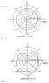
- Figs. 6 and 7 show the radiation pattern characteristic of the Fig. 1 embodiment and the radiation pattern characteristic of the Fig. 11 prior art example in an X-Y plane, respectively.
- the average gain is -8.5 dB at 1.9 GHz.
- the average gain is -12.2 dB at 1.9 GHz.
- Figs. 8 and 9 show the radiation pattern characteristics of the Fig. 1 embodiment and the Fig. 11 prior art example in an X-Y plane, respectively.
- the average gain is -8.1 dB at 1.9 GHz.
- the average gain is -11.4 dB at 1.9 GHz.
- the average gain in the radiation pattern characteristic of this embodiment improves by 3 to 4 dB as compared with that of the prior art example.
- the mounting substrate (or a sub-mounting substrate) 11 on which the surface mounting antenna 10 (20) is mounted as described above is installed in a communication apparatus 30. Also in this instance, its radiation pattern characteristics are similar to those as shown in Figs. 6 and 8.
- a surface mounting antenna is mounted in the vicinity of one corner of a mounting substrate, the surface mounting antenna is mounted on the mounting substrate so that an open end of a radiation electrode faces in a direction away from at least one side of two sides constituting the corner, the image current passes through the central portion of the mounting substrate, with the result that the wrapping of the electromagnetic field in the Z direction around an edge is reducible to lessen the conductor loss so that the gain improves.
- a communication apparatus having the mounting substrate equipped with the surface mounting antenna mounted as mentioned before can also produce the improvement in the gain.
- the shape of the radiation electrode 2, 22 is not restricted to the described shapes.
- the radiation electrode 2, 22 of the surface mounting antenna 10, 20 can also be formed as a stright strip line.
Landscapes
- Engineering & Computer Science (AREA)
- Computer Networks & Wireless Communication (AREA)
- Physics & Mathematics (AREA)
- Electromagnetism (AREA)
- Support Of Aerials (AREA)
- Details Of Aerials (AREA)
- Waveguide Aerials (AREA)
Abstract
Description
- The present invention relates to a method of mounting or packaging a surface mounting antenna on a mounting substrate, which is applicable to mobile body communication equipment such as a portable telephone system and radio LAN (Local Area Network) systems, and a communication apparatus equipped with this mounting substrate.
- Referring to Fig. 11, a description will be made hereinbelow of the prior method of mounting a surface mounting antenna on a mounting substrate. In the illustration,
numeral 40 represents a surface mounting antenna which is mounted in the vicinity of one corner of the surface of amounting substrate 41. In thissurface mounting antenna 40, an L-shaped radiation electrode 42 and asupply electrode 43 are formed such that a gap g is interposed therebetween. However, in the case of the prior art method of mounting thesurface mounting antenna 40 on themounting substrate 41, an open end 42a of theradiation electrode 42 of thesurface mounting antenna 40 faces one side 41a of two sides constituting the aforesaid one corner of themounting substrate 41 as indicated by an arrow, which lowers the gain. This is because an image current flowing in a ground electrode (a portion indicated by dotted lines) gathers in the vicinity of the one side 41a and an electromagnetic field in the Z direction (toward the upper end portion of the mounting substrate) wraps around an edge to produce a conductor loss. In addition, a communication apparatus having such a mounting substrate also causes the gain to lower. - Accordingly, it is an object of the present invention to provide a method of mounting a surface mounting antenna on a mounting substrate, which is capable of making the image current flow in the central portion of the mounting substrate to reduce the conductor loss, and further to provide a communication apparatus equipped with this mounting substrate.
- For this purpose, in a surface mounting antenna mounting method according to the present invention, when an electromotive type surface mounting antenna is mounted in the vicinity of one corner defined by the intersection of two sides of a mounting substrate, the surface mounting antenna is mounted on the mounting substrate so that an open end of a radiation electrode of the surface mounting antenna faces in a direction away from at least one side of the two sides.
- Furthermore, in accordance with this invention, the above-mentioned surface mounting antenna is constructed as an electromotive type surface mounting antenna, wherein the radiation electrode is bent to have a substantially L-shaped or substantially U-shaped configuration so that one end is open and the other end is short-circuited, and the radiation electrode and a supply electrode for exciting it are formed on one main surface of a base, made of a dielectric or magnetic substance, in a state where a gap is interposed therebetween, and the radiation electrode and the supply electrode are respectively connected to a ground terminal and a supply terminal formed on any one of end surfaces of the base.
- Still further, in accordance with this invention, there is provided a communication apparatus equipped with a mounting substrate having the aforesaid surface mounting antenna.
- As described above, according to this invention, since, when mounting the surface mounting antenna in the vicinity of one corner of the mounting substrate, the surface mounting antenna is mounted on the mounting substrate so that the open end of the surface mounting antenna faces in a direction of separating from at least one side of the two sides producing that corner, the image current flows in the central portion of the mounting substrate to lessen the wrapping of the electromagnetic field in the Z direction around the edge for reducing the conductor loss while increasing the gain. In addition, a communication apparatus having the mounting substrate equipped with this surface mounting antenna is also capable of improving the gain.
- The objects and features of the present invention will become more readily apparent from the following detailed description of the preferred embodiments taken in conjunction with the accompanying drawings in which:
- Fig. 1 is a perspective view useful for describing a method of mounting a surface mounting antenna on a mounting substrate according to the present invention;
- Fig. 2 is an enlarged perspective view showing the surface mounting antenna of Fig. 1;
- Fig. 3 is a perspective view showing a surface mounting antenna on a mounting substrate according to a further embodiment of the present invention;
- Fig. 4 is an enlarged perspective view showing another surface mounting antenna;
- Fig. 5 is a perspective view showing the surface mounting antenna of Fig. 4 mounted on a mounting substrate;
- Fig. 6 is an illustration of a radiation pattern characteristic of a mounting substrate according to the invention in an X-Y plane;
- Fig. 7 is an illustration of a radiation pattern characteristic of a prior art mounting substrate in an X-Y plane;
- Fig. 8 is an illustration of a radiation pattern characteristic of a mounting substrate according to the invention in an X-Z plane;
- Fig. 9 is an illustration of a radiation pattern characteristic of a prior art mounting substrate in an X-Z plane;
- Fig. 10 is a perspective view showing a communication apparatus according to the invention; and
- Fig. 11 is a perspective view available for explaining a prior art method of mounting a surface mounting antenna on a mounting substrate.
- Referring to the drawings, a description will be made hereinbelow of an embodiment of the present invention. Fig. 1 is a perspective view useful for describing a method of mounting a surface mounting antenna on a mounting substrate. In the illustration,
numeral 10 designates a surface mounting antenna which is also shown in an enlarged condition in Fig. 2. On a surface of abase 1 of thesurface mounting antenna 10, made of a dielectric substance or magnetic substance, aradiation electrode 2 of λ/4 approximation and with an L-shaped configuration and asupply electrode 3 are formed in a state where a gap g is interposed therebetween. Theradiation electrode 2 has anopen end 2a at its one end and further has a short-circuitedend 2b at its other end. This short-circuitedend 2b is connected to a short-circuiting terminal 4 formed to extend over one end surface 1a and rear surface of thebase 1, whereas thesupply electrode 3 is connected to asupply terminal 5 made to extend over the one end surface 1a and rear surface of thebase 1. - The
supply electrode 3 and theopen end 2a of theradiation electrode 2 are spaced by a distance d on average from each other and come into an electric field coupling to each other by a capacity Cd developed due to the separation of the distance d therebetween. Although thesupply electrode 3 and theradiation electrode 2 are in the closest relation to each other by way of the gap g disposed therebetween, the short-circuitedend 2b portion is inductive and hence the degree of coupling therebetween is small. On the other hand, although thesupply electrode 3 and theopen end 2a are separated from each other, thesurface mounting antenna 10 itself is small in size so that the degree of coupling therebetween is relatively large. - With the above-described construction, the
surface mounting antenna 10 can be mounted in the vicinity of one corner of amounting substrate 11 as shown in Fig. 1. Thesurface antenna 10 is mounted on themounting substrate 11 so that theopen end 2a of theradiation electrode 2 faces in a direction away from at least oneside 11a of two sides or edges constituting one corner as indicated by an arrow. Owing to this mounting of thesurface mounting antenna 10 on themounting substrate 11, the image current flows in the central portion of themounting substrate 11, with the result that the wrapping of the electromagnetic field in the Z direction around the edge is reducible to lessen the conductor loss. In this case, although not separating from theother side 11b, the separation from at least the oneside 11a causes the gain to heighten. - Fig. 3 illustrates a further embodiment according to the present invention. The structure of the
surface mounting antenna 10 is substantially the same as the structure of the antenna described with reference to Fig. 1. As shown in Fig. 3, thesurface antenna 10 is mounted on themounting substrate 11 such that theopen end 2a of theradiation electrode 2 faces in a direction that faces away from bothsides mounting substrate 11. - Fig. 4 illustrates a
surface mounting antenna 20 having aradiation electrode 22 with a substantially U-shaped configuration. Also with this structure, owing to a capacity Cd produced between anopen end 22a of theradiation electrode 22 and thesupply electrode 3, thesupply electrode 3 and theradiation electrode 22 chiefly come into electromagnetic field coupling to each other. - Fig. 5 illustrates the surface mounting antenna shown in Fig. 4 mounted on a
mountin substrate 11. Thesurface antenna 20 is mounted to themounting substrate 11 such that theopen end 2a of theradiation electrode 22 faces in a direction away from the two sides or edges consituting one corner of thesubstrate 11. - Secondly, the radiation pattern characteristics of the mounting substrate of Fig. 1 and the prior art mounting substrate of Fig. 11 will be described hereinbelow with reference to Figs. 6 to 9. Figs. 6 and 7 show the radiation pattern characteristic of the Fig. 1 embodiment and the radiation pattern characteristic of the Fig. 11 prior art example in an X-Y plane, respectively. In the case of the embodiment shown in Fig. 6, the average gain is -8.5 dB at 1.9 GHz. On the other hand, in the case of the prior art example shown in Fig. 7, the average gain is -12.2 dB at 1.9 GHz. Further, Figs. 8 and 9 show the radiation pattern characteristics of the Fig. 1 embodiment and the Fig. 11 prior art example in an X-Y plane, respectively. In the case of the embodiment shown in Fig. 8, the average gain is -8.1 dB at 1.9 GHz. On the other hand, in the case of the prior art example shown in Fig. 9, the average gain is -11.4 dB at 1.9 GHz. As obvious from Figs. 6 to 9, the average gain in the radiation pattern characteristic of this embodiment improves by 3 to 4 dB as compared with that of the prior art example.
- Furthermore, referring to Fig. 10, a description will be made hereinbelow of a communication apparatus having a mounting substrate equipped with a surface mounting antenna according to the invention. The mounting substrate (or a sub-mounting substrate) 11 on which the surface mounting antenna 10 (20) is mounted as described above is installed in a
communication apparatus 30. Also in this instance, its radiation pattern characteristics are similar to those as shown in Figs. 6 and 8. - According to the invention, since, when a surface mounting antenna is mounted in the vicinity of one corner of a mounting substrate, the surface mounting antenna is mounted on the mounting substrate so that an open end of a radiation electrode faces in a direction away from at least one side of two sides constituting the corner, the image current passes through the central portion of the mounting substrate, with the result that the wrapping of the electromagnetic field in the Z direction around an edge is reducible to lessen the conductor loss so that the gain improves. In addition, a communication apparatus having the mounting substrate equipped with the surface mounting antenna mounted as mentioned before can also produce the improvement in the gain.
- Further to the embodiments described above, it is noted that the shape of the
radiation electrode radiation electrode surface mounting antenna - It should be understood that the foregoing relates to only preferred embodiments of the present invention, and that it is intended to cover all changes and modifications of the embodiments of the invention herein used for the purposes of the disclosure, which do not constitute departures from the spirit and scope of the invention.
Claims (6)
- A method of mounting a surface mounting antenna on a mounting substrate (11) comprising the steps of: mounting an electromotive type surface mounting antenna (10; 20) in a vicinity of one corner defined by an intersection of two sides (11a, 11b) of said mounting substrate (11) and disposing said surface mounting antenna (10; 20) on said mounting substrate (10) with an open end (2a; 22a) of a radiation electrode (2; 22) of said surface mounting antenna (10; 20) facing in a direction away from at least one side (11a) of said two sides (11a, 11b) of the substrate (11).
- A method of mounting a surface mounting antenna on a mounting substrate (11) comprising the steps of: mounting an electromotive type surface mounting antenna (10; 20) in a vicinity of one corner defined by an intersection of two sides (11a, 11b) of said mounting substrate (11) and disposing said surface mounting antenna (10; 20) on said mounting substrate (10) with an open end (2a; 22a) of a radiation electrode (2; 22) of said surface mounting antenna (10; 20) facing in a direction away from both of said two sides (11a, 11b) of the substrate (11).
- The method of claim 1 or 2, further comprising forming said radiation electrode (2; 22) of said surface mounting antenna (10; 20) to have one of a substantially L-shaped configuration and a substantially U-shaped configuration with a first end portion being open (2a; 22a) and a second end portion being short-circuited (2b), and arranging said radiation electrode (2; 22) and a supply electrode (3) for exciting said radiation electrode (2; 22) with a gap (g) therebetween on a main surface of the substrate comprising at least one of a dielectric substance and a magnetic substance, and connecting said radiation electrode (2; 22) and said supply electrode (3) respectively to a ground terminal and a supply terminal formed on at least one end surface of said substrate.
- A communication apparatus (30) comprising at least one of an electromagnetic frequency transmitter circuit and an electromagnetic frequency receiver circuit and further comprising a surface mounting antenna (10; 20) disposed on a mounting substrate (11) connected to at least one of the transmitter circuit and receiver circuit, the antenna comprising an electromagnetic surface mounting antenna mounted in a vicinity of one corner defined by an intersection of two sides (11a, 11b) of said mounting substrate (11), the surface mounting antenna (10; 20) being disposed on said mounting substrate (11) with an open end (2a; 22a) of a radiation electrode (2; 22) of said surface mounting antenna (10; 20) facing in a direction away from at least one side (11a) of said two sides (11a, 11b) of the substrate (11).
- A communication apparatus (30) comprising at least one of an electromagnetic frequency transmitter circuit and an electromagnetic frequency receiver circuit and further comprising a surface mounting antenna (10; 20) disposed on a mounting substrate (11) connected to at least one of the transmitter circuit and receiver circuit, the antenna comprising an electromagnetic surface mounting antenna mounted in a vicinity of one corner defined by an intersection of two sides (11a, 11b) of said mounting substrate (11), the surface mounting antenna (10; 20) being disposed on said mounting substrate (11) with an open end (2a; 22a) of a radiation electrode (2; 22) of said surface mounting antenna (10; 20) facing in a direction away from both of said two sides (11a, 11b) of the substrate (11).
- The communication apparatus of claim 4 or 5, wherein the radiation electrode (2; 22) of said surface mounting antenna (10; 20) has one of a substantially L-shaped configuration and a substantially U-shaped configuration with a first end portion being open (2a; 22a) and a second end portion being short-circuited (2b), a supply electrode (3) being disposed adjacent the radiation electrode (2; 22) , the supply electrode (3) disposed adjacent the radiation electrode (2; 22) with a gap (g) therebetween and being provided for exciting the radiation electrode (2; 22), the radiation electrode (2; 22) and the supply electrode (3) being provided on a main surface of the substrate comprising one of a dielectric substance and a magnetic substance, the radiation electrode (2; 22) and the supply electrode (3) being connected respectively to a ground terminal and a supply terminal formed on at least one end surface of said substrate.
Applications Claiming Priority (3)
| Application Number | Priority Date | Filing Date | Title |
|---|---|---|---|
| JP3090696 | 1996-02-19 | ||
| JP30906/96 | 1996-02-19 | ||
| JP3090696 | 1996-02-19 |
Publications (3)
| Publication Number | Publication Date |
|---|---|
| EP0790668A2 true EP0790668A2 (en) | 1997-08-20 |
| EP0790668A3 EP0790668A3 (en) | 1999-09-22 |
| EP0790668B1 EP0790668B1 (en) | 2003-06-18 |
Family
ID=12316769
Family Applications (1)
| Application Number | Title | Priority Date | Filing Date |
|---|---|---|---|
| EP97102704A Expired - Lifetime EP0790668B1 (en) | 1996-02-19 | 1997-02-19 | Antenna apparatus and communication apparatus using the same |
Country Status (7)
| Country | Link |
|---|---|
| US (1) | US5943019A (en) |
| EP (1) | EP0790668B1 (en) |
| KR (1) | KR100253680B1 (en) |
| AU (1) | AU683606B2 (en) |
| CA (1) | CA2197939C (en) |
| DE (1) | DE69722835T2 (en) |
| TW (1) | TW356610B (en) |
Cited By (6)
| Publication number | Priority date | Publication date | Assignee | Title |
|---|---|---|---|---|
| EP0942488A3 (en) * | 1998-02-24 | 2000-04-19 | Murata Manufacturing Co., Ltd. | Antenna device and radio device comprising the same |
| WO2001003238A1 (en) * | 1999-06-29 | 2001-01-11 | Siemens Aktiengesellschaft | Integrable dual-band antenna |
| EP0993069A3 (en) * | 1998-10-05 | 2001-04-25 | Murata Manufacturing Co., Ltd. | Surface mount circularly polarized wave antenna and communication apparatus using the same |
| EP1069644A3 (en) * | 1999-07-16 | 2002-05-02 | Mitsubishi Materials Corporation | Antenna assembly |
| SG94695A1 (en) * | 1996-02-14 | 2003-03-18 | Murata Manufacturing Co | Surface-mount-type antenna and communication equipment using same |
| KR100723086B1 (en) * | 1999-08-24 | 2007-05-29 | 레인지스타 인터내셔널 코포레이션 | Asymmetric dipole antenna assembly |
Families Citing this family (9)
| Publication number | Priority date | Publication date | Assignee | Title |
|---|---|---|---|---|
| US6304222B1 (en) * | 1997-12-22 | 2001-10-16 | Nortel Networks Limited | Radio communications handset antenna arrangements |
| EP1039576B1 (en) * | 1999-03-15 | 2004-02-04 | Murata Manufacturing Co., Ltd. | Antenna apparatus and communication apparatus using the antenna apparatus |
| JP4263820B2 (en) * | 1999-10-21 | 2009-05-13 | 株式会社ヨコオ | Flat antenna for circular polarization |
| GB2358963A (en) * | 2000-02-02 | 2001-08-08 | Nokia Mobile Phones Ltd | Mobile 'phone antenna |
| SE516842C2 (en) * | 2000-07-10 | 2002-03-12 | Allgon Ab | Antenna device for a portable radio communication device |
| KR20020061103A (en) * | 2001-01-12 | 2002-07-22 | 후루까와덴끼고오교 가부시끼가이샤 | Antenna device and terminal with the antenna device |
| US6801164B2 (en) | 2001-08-27 | 2004-10-05 | Motorola, Inc. | Broad band and multi-band antennas |
| TWM276330U (en) * | 2005-04-15 | 2005-09-21 | Wistron Neweb Corp | Antenna |
| US7183983B2 (en) * | 2005-04-26 | 2007-02-27 | Nokia Corporation | Dual-layer antenna and method |
Family Cites Families (13)
| Publication number | Priority date | Publication date | Assignee | Title |
|---|---|---|---|---|
| US4395713A (en) * | 1980-05-06 | 1983-07-26 | Antenna, Incorporated | Transit antenna |
| US4403221A (en) * | 1981-08-10 | 1983-09-06 | Honeywell Inc. | Millimeter wave microstrip antenna |
| GB2152757B (en) * | 1984-01-05 | 1987-10-14 | Plessey Co Plc | Antenna |
| GB2213995A (en) * | 1987-12-22 | 1989-08-23 | Philips Electronic Associated | Coplanar patch antenna |
| AT393054B (en) * | 1989-07-27 | 1991-08-12 | Siemens Ag Oesterreich | TRANSMITTER AND / OR RECEIVING ARRANGEMENT FOR PORTABLE DEVICES |
| DE69422327T2 (en) * | 1993-04-23 | 2000-07-27 | Murata Mfg. Co., Ltd. | Surface mount antenna unit |
| GB9309368D0 (en) * | 1993-05-06 | 1993-06-16 | Ncr Int Inc | Antenna apparatus |
| JP3185513B2 (en) * | 1994-02-07 | 2001-07-11 | 株式会社村田製作所 | Surface mount antenna and method of mounting the same |
| US5644319A (en) * | 1995-05-31 | 1997-07-01 | Industrial Technology Research Institute | Multi-resonance horizontal-U shaped antenna |
| US5696517A (en) * | 1995-09-28 | 1997-12-09 | Murata Manufacturing Co., Ltd. | Surface mounting antenna and communication apparatus using the same |
| US5748149A (en) * | 1995-10-04 | 1998-05-05 | Murata Manufacturing Co., Ltd. | Surface mounting antenna and antenna apparatus |
| JP3319268B2 (en) * | 1996-02-13 | 2002-08-26 | 株式会社村田製作所 | Surface mount antenna and communication device using the same |
| JP3114605B2 (en) * | 1996-02-14 | 2000-12-04 | 株式会社村田製作所 | Surface mount antenna and communication device using the same |
-
1997
- 1997-02-19 TW TW086102229A patent/TW356610B/en not_active IP Right Cessation
- 1997-02-19 CA CA002197939A patent/CA2197939C/en not_active Expired - Lifetime
- 1997-02-19 EP EP97102704A patent/EP0790668B1/en not_active Expired - Lifetime
- 1997-02-19 AU AU14791/97A patent/AU683606B2/en not_active Expired
- 1997-02-19 DE DE69722835T patent/DE69722835T2/en not_active Expired - Lifetime
- 1997-02-19 KR KR1019970004959A patent/KR100253680B1/en not_active Expired - Lifetime
- 1997-02-19 US US08/802,243 patent/US5943019A/en not_active Expired - Lifetime
Cited By (9)
| Publication number | Priority date | Publication date | Assignee | Title |
|---|---|---|---|---|
| SG94695A1 (en) * | 1996-02-14 | 2003-03-18 | Murata Manufacturing Co | Surface-mount-type antenna and communication equipment using same |
| EP0942488A3 (en) * | 1998-02-24 | 2000-04-19 | Murata Manufacturing Co., Ltd. | Antenna device and radio device comprising the same |
| US6147650A (en) * | 1998-02-24 | 2000-11-14 | Murata Manufacturing Co., Ltd. | Antenna device and radio device comprising the same |
| EP0993069A3 (en) * | 1998-10-05 | 2001-04-25 | Murata Manufacturing Co., Ltd. | Surface mount circularly polarized wave antenna and communication apparatus using the same |
| WO2001003238A1 (en) * | 1999-06-29 | 2001-01-11 | Siemens Aktiengesellschaft | Integrable dual-band antenna |
| EP1069644A3 (en) * | 1999-07-16 | 2002-05-02 | Mitsubishi Materials Corporation | Antenna assembly |
| US6531983B1 (en) | 1999-07-16 | 2003-03-11 | Mitsubishi Materials Corporation | Method for antenna assembly and an antenna assembly with a conductive film formed on convex portions |
| KR100702089B1 (en) * | 1999-07-16 | 2007-04-02 | 미츠비시 마테리알 가부시키가이샤 | Antenna structure |
| KR100723086B1 (en) * | 1999-08-24 | 2007-05-29 | 레인지스타 인터내셔널 코포레이션 | Asymmetric dipole antenna assembly |
Also Published As
| Publication number | Publication date |
|---|---|
| AU1479197A (en) | 1997-08-28 |
| KR100253680B1 (en) | 2000-04-15 |
| KR970063814A (en) | 1997-09-12 |
| DE69722835D1 (en) | 2003-07-24 |
| US5943019A (en) | 1999-08-24 |
| EP0790668B1 (en) | 2003-06-18 |
| AU683606B2 (en) | 1997-11-13 |
| CA2197939C (en) | 2001-05-01 |
| DE69722835T2 (en) | 2004-05-06 |
| CA2197939A1 (en) | 1997-08-20 |
| EP0790668A3 (en) | 1999-09-22 |
| TW356610B (en) | 1999-04-21 |
Similar Documents
| Publication | Publication Date | Title |
|---|---|---|
| US5943019A (en) | Method of mounting surface mounting antenna on mounting substrate antenna apparatus and communication apparatus employing mounting substrate | |
| JP3319268B2 (en) | Surface mount antenna and communication device using the same | |
| US6515625B1 (en) | Antenna | |
| US4658259A (en) | On-glass antenna | |
| US6218992B1 (en) | Compact, broadband inverted-F antennas with conductive elements and wireless communicators incorporating same | |
| US5892490A (en) | Meander line antenna | |
| US4992800A (en) | Windshield mounted antenna assembly | |
| JP2001522558A (en) | Antenna for wireless communication device | |
| EP1267440A2 (en) | Antenna element with conductors formed on outer surfaces of device substrate | |
| JP2000068731A (en) | Wireless communication device and throttle antenna | |
| JP3980172B2 (en) | Broadband antenna | |
| US6700541B2 (en) | Antenna element with conductors formed on outer surfaces of device substrate | |
| US20060044186A1 (en) | Dual band antenna system | |
| JPH04249407A (en) | Automobile glass antenna | |
| US5945950A (en) | Stacked microstrip antenna for wireless communication | |
| US5497167A (en) | Antenna for mounting on a vehicle window | |
| JPH06334420A (en) | Plate antenna with parasitic element | |
| JP2001144524A (en) | Multi-frequency common antenna | |
| JPH04249405A (en) | Automobile glass antenna | |
| EP0982798B1 (en) | Antenna device and communication apparatus including the same | |
| US6002366A (en) | Surface mount antenna and communication apparatus using same | |
| EP3376594B1 (en) | Automotive antenna | |
| JPH0878941A (en) | Repeater antenna system | |
| JPH071619U (en) | Flat antenna | |
| JP2509970B2 (en) | Mobile communication terminal |
Legal Events
| Date | Code | Title | Description |
|---|---|---|---|
| PUAI | Public reference made under article 153(3) epc to a published international application that has entered the european phase |
Free format text: ORIGINAL CODE: 0009012 |
|
| 17P | Request for examination filed |
Effective date: 19970219 |
|
| AK | Designated contracting states |
Kind code of ref document: A2 Designated state(s): DE FI FR GB SE |
|
| PUAL | Search report despatched |
Free format text: ORIGINAL CODE: 0009013 |
|
| AK | Designated contracting states |
Kind code of ref document: A3 Designated state(s): DE FI FR GB SE |
|
| RIC1 | Information provided on ipc code assigned before grant |
Free format text: 6H 01Q 9/04 A, 6H 01Q 1/24 B, 6H 01Q 1/38 B, 6H 01Q 19/00 B |
|
| 17Q | First examination report despatched |
Effective date: 20011214 |
|
| GRAH | Despatch of communication of intention to grant a patent |
Free format text: ORIGINAL CODE: EPIDOS IGRA |
|
| GRAH | Despatch of communication of intention to grant a patent |
Free format text: ORIGINAL CODE: EPIDOS IGRA |
|
| GRAA | (expected) grant |
Free format text: ORIGINAL CODE: 0009210 |
|
| AK | Designated contracting states |
Designated state(s): DE FI FR GB SE |
|
| PG25 | Lapsed in a contracting state [announced via postgrant information from national office to epo] |
Ref country code: FI Free format text: LAPSE BECAUSE OF FAILURE TO SUBMIT A TRANSLATION OF THE DESCRIPTION OR TO PAY THE FEE WITHIN THE PRESCRIBED TIME-LIMIT Effective date: 20030618 |
|
| REG | Reference to a national code |
Ref country code: GB Ref legal event code: FG4D |
|
| REF | Corresponds to: |
Ref document number: 69722835 Country of ref document: DE Date of ref document: 20030724 Kind code of ref document: P |
|
| PG25 | Lapsed in a contracting state [announced via postgrant information from national office to epo] |
Ref country code: SE Free format text: LAPSE BECAUSE OF FAILURE TO SUBMIT A TRANSLATION OF THE DESCRIPTION OR TO PAY THE FEE WITHIN THE PRESCRIBED TIME-LIMIT Effective date: 20030918 |
|
| PLBE | No opposition filed within time limit |
Free format text: ORIGINAL CODE: 0009261 |
|
| STAA | Information on the status of an ep patent application or granted ep patent |
Free format text: STATUS: NO OPPOSITION FILED WITHIN TIME LIMIT |
|
| ET | Fr: translation filed | ||
| 26N | No opposition filed |
Effective date: 20040319 |
|
| REG | Reference to a national code |
Ref country code: FR Ref legal event code: PLFP Year of fee payment: 20 |
|
| PGFP | Annual fee paid to national office [announced via postgrant information from national office to epo] |
Ref country code: DE Payment date: 20160218 Year of fee payment: 20 |
|
| PGFP | Annual fee paid to national office [announced via postgrant information from national office to epo] |
Ref country code: GB Payment date: 20160217 Year of fee payment: 20 Ref country code: FR Payment date: 20160218 Year of fee payment: 20 |
|
| REG | Reference to a national code |
Ref country code: DE Ref legal event code: R071 Ref document number: 69722835 Country of ref document: DE |
|
| REG | Reference to a national code |
Ref country code: GB Ref legal event code: PE20 Expiry date: 20170218 |
|
| PG25 | Lapsed in a contracting state [announced via postgrant information from national office to epo] |
Ref country code: GB Free format text: LAPSE BECAUSE OF EXPIRATION OF PROTECTION Effective date: 20170218 |