EP0789855B1 - Optical instrument with an anti-backlash focusing mechanism - Google Patents
Optical instrument with an anti-backlash focusing mechanism Download PDFInfo
- Publication number
- EP0789855B1 EP0789855B1 EP96925852A EP96925852A EP0789855B1 EP 0789855 B1 EP0789855 B1 EP 0789855B1 EP 96925852 A EP96925852 A EP 96925852A EP 96925852 A EP96925852 A EP 96925852A EP 0789855 B1 EP0789855 B1 EP 0789855B1
- Authority
- EP
- European Patent Office
- Prior art keywords
- sleeve
- cylindrical member
- housing
- focusing device
- bore
- Prior art date
- Legal status (The legal status is an assumption and is not a legal conclusion. Google has not performed a legal analysis and makes no representation as to the accuracy of the status listed.)
- Expired - Lifetime
Links
- 230000003287 optical effect Effects 0.000 title claims description 9
- 230000008878 coupling Effects 0.000 claims description 8
- 238000010168 coupling process Methods 0.000 claims description 8
- 238000005859 coupling reaction Methods 0.000 claims description 8
- 230000006835 compression Effects 0.000 claims description 3
- 238000007906 compression Methods 0.000 claims description 3
- 230000001419 dependent effect Effects 0.000 claims 3
- 238000007689 inspection Methods 0.000 claims 1
- 210000003644 lens cell Anatomy 0.000 description 19
Images
Classifications
-
- G—PHYSICS
- G02—OPTICS
- G02B—OPTICAL ELEMENTS, SYSTEMS OR APPARATUS
- G02B7/00—Mountings, adjusting means, or light-tight connections, for optical elements
- G02B7/02—Mountings, adjusting means, or light-tight connections, for optical elements for lenses
- G02B7/04—Mountings, adjusting means, or light-tight connections, for optical elements for lenses with mechanism for focusing or varying magnification
-
- G—PHYSICS
- G02—OPTICS
- G02B—OPTICAL ELEMENTS, SYSTEMS OR APPARATUS
- G02B23/00—Telescopes, e.g. binoculars; Periscopes; Instruments for viewing the inside of hollow bodies; Viewfinders; Optical aiming or sighting devices
- G02B23/24—Instruments or systems for viewing the inside of hollow bodies, e.g. fibrescopes
- G02B23/2407—Optical details
Definitions
- the present invention relates to an optical instrument with a focusing mechanism designed to eliminate backlash.
- the present invention is described with particular reference to a focusing mechanism for a borescope or endoscope used for viewing a location inaccessible to or remote from the user but is applicable to other types of optical instrument.
- a housing or chassis member containing a focusing lens mounted in a cylindrical focusing lens cell, and a focus control member.
- the focusing lens cell is slidably received within the chassis and linked to the focus control member such that rotation of the focus control member moves the focusing lens cell axially so that a focused image can be provided for the user's eye or at the CCD in a CCTV camera or the film plane in a still camera.
- the focus control member comprises a sleeve rotatably mounted on the chassis and having a helical groove in its interior surface.
- a pin projecting radially from the focusing lens cell extends through an axial slot in the chassis wall and engages in the helical groove. Accordingly, rotation of the focus control member causes axial movement of the focusinq lens cell within the chassis.
- the present invention seeks to provide an anti-backlash focusing mechanism for an optical instrument in which the above mentioned clearances between the focus control member and the focusing lens cell are eliminated.
- the present invention provides a focusing device for an optical instrument comprising focusing lens means mounted in a first cylindrical member coaxially located in a cylindrical bore in a housing, the first cylindrical member being slidable and constrained to move axially within the bore; focus control means comprising a sleeve rotatably mounted on the housing and a first coupling mechanism between the sleeve and the first cylindrical member whereby rotation of the sleeve causes axial movement of the first cylindrical member; the device further comprising a second cylindrical member also coaxially located in the bore of the housing adjacent to the first cylindrical member and being slidable and constrained to move axially with the bore; a second coupling mechanism between the sleeve and the second cylindrical member whereby rotation of the sleeve causes axial movement of the second cylindrical member synchronously with movement of the first cylindrical member; biasing means urging the first and second cylindrical members towards each other to eliminate clearances between them and the sleeve and between the first and second cylindrical members and the housing and
- the first cylindrical member is constrained to move axially within the bore by means of a first pin projecting radially outwardly from the first cylindrical member and extending through a first axial slot in the wall of the housing.
- the first coupling mechanism between the first cylindrical member and the sleeve preferably comprises a first helical slot formed in the sleeve in which the first pin engages.
- the second cylindrical member may be constrained to move axially within the bore by means of a second pin projecting radially outwardly from the second cylindrical member and extending through a second axial slot in the wall of the housing.
- the second coupling mechanism between the second cylindrical member and the sleeve may comprise a second helical slot formed in the sleeve in which the second pin engages.
- the first and second axial slots are parallel to one another and are axially and circumferentially spaced from one another.
- first and second helical slots are parallel to one another and axially and circumferentially spaced from one another.
- the biasing means comprises a spring means urging the first and second cylindrical members together.
- the spring means may comprise an extension spring which may be connected between the first and the second pins.
- the means to prevent relative axial movement between the sleeve and the housing comprises a second biasing means urging the sleeve into abutment with a stop member on the housing.
- the second biasing means also comprises spring means, which may be a compression spring mounted between the sleeve and a locking member located on the housing.
- This system has the advantage that the focus control member and the focusing lens cell always move simultaneously, which is essential for any specialist borescope in which a linkage between the focus control member and the focusing lens cell has to be backlash free.
- an instrument for use as a borescope or endoscope comprises a tube, the distal end of which can be inserted into an inaccessible location.
- An optical system is provided in the tube to relay an image of an object at the inaccessible location to the proximal end of the tube.
- the proximal end of the tube terminates in a housing or body through which the user looks to view the image.
- a focusing mechanism is provided in the housing which is adjustable to present an in-focus image to the user.
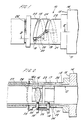
- a focusing mechanism (10) in accordance with the present invention comprises a generally cylindrical housing or chassis member (11) having a cylindrical bore (12) extending through it.
- the proximal end of the chassis (11) is to the left hand side in the figures, while the distal end, to which in use the tube containing the image relaying system is connected, is to the right.
- the outer surface of the chassis (11) comprises a smaller diameter portion (13) and a larger diameter portion (14) arranged distally of the small diameter portion (13) and separated from it by a shoulder (15).
- a focusing lens cell comprising a cylindrical member (16) in which focusing lens means, here shown as single lens (16a), is fixed.
- a second cylindrical member (17) Distally adjacent to the cylindrical lens cell (16) is a second cylindrical member (17) also slidably received in the bore (12).
- the chassis (11), focusing lens cell (16) and the cylindrical member (17) are all coaxial with one another.
- the lens cell (16) and second cylindrical member (17) have the same outside diameter.
- Both the lens cell (16) and the second cylindrical member (17) have a respective pin (18,19) fixedly secured thereto and projecting radially outwardly.
- Each pin (18,19) extends through a respective axial slot (20,21) formed in the wall of the smaller diameter portion (13) of the chassis (11).
- the axial slots (20,21) are parallel and are formed axially and circumferentially spaced from one another, as is shown most clearly in Figure 1.
- a focus control member (22) in the form of a sleeve is rotatably mounted on the smaller diameter portion (13) of the chassis (11) adjacent the shoulder (15).
- a pair of parallel helical slots (23,24) are formed in the focus control member (22). These slots have the same lead characteristic and the starts of the two slots are separated axially and circumferentially from one another by an amount depending on the optical specification and physical dimensions of the instrument.
- the pin (18) secured to the focusing lens cell (16) extends through the helical slot (23) which is closest to the proximal end of the focus control member (22).
- the pin (19) secured to the second cylindrical member (17) extends through the other helical slot (24) nearest to the distal end of focus control member (22).
- the heads of the two pins (18,19) protrude outwardly from the helical slots (23,24).
- Biasing means in the form of an extension spring (25) is attached between the heads of two pins (18,19) and extends across the outer surface of the focus control member (22).
- the spring (25) therefore urges the two cylinders (16,17) towards each other and eliminates any clearances between them and the focus control member (22) and between the two cylinders (16,17) and the chassis (11).
- the spring force urging the two cylinders (16,17) towards each other is constant due to the similar lead characteristics of the two slots (23,24) in the focus control member (22).
- this second biasing means comprising a compression spring (26) located between the proximal end of the focus control member (22) and a locking ring member (27) mounted on the chassis (11), which spring (26) urges the focus control member (22) into abutment with the shoulder (15).
- the second biasing means is illustrated in the form of a spring ring but any form of spring means which will urge the focus control member (22) and the shoulder (15) together may be used.
Landscapes
- Physics & Mathematics (AREA)
- General Physics & Mathematics (AREA)
- Optics & Photonics (AREA)
- Astronomy & Astrophysics (AREA)
- Instruments For Viewing The Inside Of Hollow Bodies (AREA)
- Endoscopes (AREA)
- Lens Barrels (AREA)
Description
Claims (14)
- Focusing device (10) for an optical instrument comprising focusing lens means (16a) mounted in a first cylindrical member (16) coaxially located in a cylindrical bore (12) in a housing (11), the first cylindrical member being slidable and constrained to move axially within the bore; focus control means comprising a sleeve (22) rotatably mounted on the housing and a first coupling mechanism (23) between the sleeve and the first cylindrical member whereby rotation of the sleeve causes axial movement of the first cylindrical member; the device further comprising a second cylindrical member (17) also coaxially located in the bore of the housing adjacent to the first cylindrical member and being slidable and constrained to move axially with the bore; a second coupling mechanism (24) between the sleeve and the second cylindrical member whereby rotation of the sleeve causes axial movement of the second cylindrical member synchronously with movement of the first cylindrical member; biasing means (25) urging the first and second cylindrical members towards each other to eliminate clearances between them and the sleeve and between the first and second cylindrical members and the housing and means (26) to prevent relative axial movement between the sleeve and the housing.
- A focusing device as claimed in claim 1, wherein the first cylindrical member is constrained to move axially within the bore by means of a first pin (18) projecting radially outwardly from the first cylindrical member and extending through a first axial slot (20) in the wall of the housing.
- A focusing device as claimed in claim 2, wherein the first coupling mechanism between the first cylindrical member and the sleeve comprises a first helical slot (23) formed in the sleeve in which the first pin engages.
- A focusing device as claimed in any preceding claim, wherein the second cylindrical member is constrained to move axially within the bore by means of a second pin (19) projecting radially outwardly from the second cylindrical member and extending through a second axial slot (21) in the wall of the housing.
- A focusing device as claimed in claim 4, wherein the second coupling mechanism between the second cylindrical member and the sleeve comprises a second helical slot (24) formed in the sleeve in which the second pin engages.
- A focusing device as claimed in claim 4 or claim 5 as dependent on claim 2 or claim 3, wherein the first and second axial slots are parallel to one another and are axially and circumferentially spaced from one another.
- A focusing device claimed in claim 5 or claim 6 as dependent on claim 5, wherein the first and second helical slots are parallel to one another and axially and circumferentially spaced from one another.
- A focusing device as claimed in any preceding claim, wherein the biasing means comprises spring means urging the first and second cylindrical members together.
- A focusing device as claimed in claim 8, wherein the spring means comprises an extension spring connected between the first and second cylindrical members.
- A focusing device as claimed in claim 9 as dependent on claims 2 and 4, wherein the extension spring is attached to the first and second pins.
- A focusing device as claimed in any preceding claim wherein the means to prevent relative axial movement between the sleeve and the housing comprises a second biasing means (26) urging the sleeve into abutment with a stop member on the housing.
- A focusing device as claimed in claim 11 wherein the second biasing means comprises second spring means urging the sleeve into abutment with the stop member. -
- A focusing device as claimed in claim 12, wherein the second spring means comprises a compression spring mounted between the sleeve and a locking member (27) located on the housing.
- Apparatus for use as a borescope or endoscope for inspection of an inaccessible object, comprising a tube having a distal end which is insertable in use into an inaccessible location and a proximal end which is accessible to the user; an optical system to relay an image of an object from the distal end to the proximal end of the tube and a housing (11) at the proximal end of the tube having a bore through which the user views the image, wherein the apparatus further comprises a focusing device (10) in accordance with any preceding claim located in the housing.
Applications Claiming Priority (3)
| Application Number | Priority Date | Filing Date | Title |
|---|---|---|---|
| GB9517889A GB2304920B (en) | 1995-09-01 | 1995-09-01 | Optical instrument with an anti-backlash focusing mechanism |
| GB9517889 | 1995-09-01 | ||
| PCT/GB1996/001807 WO1997009650A1 (en) | 1995-09-01 | 1996-07-26 | Optical instrument with an anti-backlash focusing mechanism |
Publications (2)
| Publication Number | Publication Date |
|---|---|
| EP0789855A1 EP0789855A1 (en) | 1997-08-20 |
| EP0789855B1 true EP0789855B1 (en) | 2001-10-17 |
Family
ID=10780069
Family Applications (1)
| Application Number | Title | Priority Date | Filing Date |
|---|---|---|---|
| EP96925852A Expired - Lifetime EP0789855B1 (en) | 1995-09-01 | 1996-07-26 | Optical instrument with an anti-backlash focusing mechanism |
Country Status (6)
| Country | Link |
|---|---|
| US (1) | US5818648A (en) |
| EP (1) | EP0789855B1 (en) |
| JP (1) | JPH10508393A (en) |
| DE (1) | DE69616014T2 (en) |
| GB (1) | GB2304920B (en) |
| WO (1) | WO1997009650A1 (en) |
Families Citing this family (4)
| Publication number | Priority date | Publication date | Assignee | Title |
|---|---|---|---|---|
| JP5324168B2 (en) * | 2008-09-12 | 2013-10-23 | 株式会社タムロン | Optical apparatus and imaging apparatus |
| US20130083182A1 (en) * | 2011-09-30 | 2013-04-04 | Fujifilm Corporation | Lens unit and camera module for endoscope |
| CN114527550A (en) * | 2022-03-04 | 2022-05-24 | 四川九洲电器集团有限责任公司 | High-precision optical focusing mechanism, device, system and equipment |
| JP7805976B2 (en) * | 2023-02-02 | 2026-01-26 | キヤノン株式会社 | Optical device and imaging device |
Family Cites Families (10)
| Publication number | Priority date | Publication date | Assignee | Title |
|---|---|---|---|---|
| GB506965A (en) * | 1937-07-16 | 1939-06-07 | Kodak Ltd | An optical system for use in recording or reproducing sound on film |
| DE1272702B (en) * | 1966-04-19 | 1968-07-11 | Schneider Co Optische Werke | Installation on photographic and cinematographic lenses with axially displaceable optical elements |
| DE1597200B1 (en) * | 1966-10-27 | 1970-03-19 | Eastman Kodak Co | Film projector for moving and still picture projection |
| JPS557764A (en) * | 1978-07-03 | 1980-01-19 | Nippon Bell Haueru Kk | Zoom lens device capable of macro photography |
| US4386829A (en) * | 1979-07-13 | 1983-06-07 | Canon Kabushiki Kaisha | Mechanical mounting system for a zoom lens assembly |
| EP0027651B1 (en) * | 1979-10-18 | 1985-04-10 | Olympus Optical Co., Ltd. | Endoscope ocular section |
| JPS57196959A (en) * | 1981-05-29 | 1982-12-03 | Olympus Optical Co | Hard endoscope |
| US4506952A (en) * | 1982-07-30 | 1985-03-26 | Philip Morris Incorporated | Lens mount |
| GB8430343D0 (en) * | 1984-11-30 | 1985-01-09 | Pilkington Perkin Elmer Ltd | Cam mechanisms |
| JP3402391B2 (en) * | 1993-02-17 | 2003-05-06 | オリンパス光学工業株式会社 | Lens barrel |
-
1995
- 1995-09-01 GB GB9517889A patent/GB2304920B/en not_active Expired - Lifetime
-
1996
- 1996-07-26 EP EP96925852A patent/EP0789855B1/en not_active Expired - Lifetime
- 1996-07-26 WO PCT/GB1996/001807 patent/WO1997009650A1/en not_active Ceased
- 1996-07-26 US US08/809,586 patent/US5818648A/en not_active Expired - Lifetime
- 1996-07-26 JP JP9510921A patent/JPH10508393A/en active Pending
- 1996-07-26 DE DE69616014T patent/DE69616014T2/en not_active Expired - Lifetime
Also Published As
| Publication number | Publication date |
|---|---|
| GB2304920A (en) | 1997-03-26 |
| GB2304920B (en) | 1999-02-24 |
| WO1997009650A1 (en) | 1997-03-13 |
| JPH10508393A (en) | 1998-08-18 |
| GB9517889D0 (en) | 1995-11-01 |
| US5818648A (en) | 1998-10-06 |
| DE69616014T2 (en) | 2002-06-06 |
| DE69616014D1 (en) | 2001-11-22 |
| EP0789855A1 (en) | 1997-08-20 |
Similar Documents
| Publication | Publication Date | Title |
|---|---|---|
| GB2267762A (en) | Optical endoscope having a zoom lens | |
| US6817976B2 (en) | Deviated distal viewing endoscope | |
| CN1670603B (en) | Telescopic lens system and camera adopting the telescopic lens system | |
| US20060055819A1 (en) | Video surveillance camera | |
| US4822154A (en) | Improvements in or relating to borescopes | |
| US7911691B2 (en) | Binoculars having diopter adjustment | |
| US20070183769A1 (en) | Retractable photographic lens | |
| JP2001503159A (en) | Optical coupler | |
| US11119308B2 (en) | Video endoscope | |
| US4351587A (en) | Apparatus for positioning eyepiece of endoscope | |
| US5818648A (en) | Optical instrument with an anti-backlash focusing mechanism | |
| JP3995444B2 (en) | Lens drive device | |
| US10560619B2 (en) | Adapter for pivoting a lens | |
| US4171880A (en) | Zoom lens system for cameras | |
| US5540650A (en) | Borescope | |
| US7265918B2 (en) | Movable member supporting mechanism, and movable member supporting mechanism for lens barrel | |
| US6333812B1 (en) | Borescope | |
| EP1818705A1 (en) | Focusing unit and optical device | |
| US5754896A (en) | Lens device having a focusing lens unit coupled to a drive ring by a coupling member and having a notch to prevent the coupling member from obstructing insertion of the focusing lens unit into the lens device | |
| JP4205927B2 (en) | Rotating and feeding mechanism for lens barrel and rotating and feeding mechanism | |
| US4247170A (en) | Zooming structure of interchangeable camera lens | |
| JP6004223B2 (en) | Lens barrel and imaging device | |
| US6088538A (en) | Zoom finder | |
| US4468107A (en) | Macro-focussing rear converter lens | |
| JP2007206710A (en) | Lens barrel |
Legal Events
| Date | Code | Title | Description |
|---|---|---|---|
| PUAI | Public reference made under article 153(3) epc to a published international application that has entered the european phase |
Free format text: ORIGINAL CODE: 0009012 |
|
| 17P | Request for examination filed |
Effective date: 19970516 |
|
| AK | Designated contracting states |
Kind code of ref document: A1 Designated state(s): DE FR |
|
| RBV | Designated contracting states (corrected) |
Designated state(s): DE FR |
|
| GRAG | Despatch of communication of intention to grant |
Free format text: ORIGINAL CODE: EPIDOS AGRA |
|
| GRAG | Despatch of communication of intention to grant |
Free format text: ORIGINAL CODE: EPIDOS AGRA |
|
| GRAH | Despatch of communication of intention to grant a patent |
Free format text: ORIGINAL CODE: EPIDOS IGRA |
|
| 17Q | First examination report despatched |
Effective date: 20010315 |
|
| GRAH | Despatch of communication of intention to grant a patent |
Free format text: ORIGINAL CODE: EPIDOS IGRA |
|
| GRAA | (expected) grant |
Free format text: ORIGINAL CODE: 0009210 |
|
| AK | Designated contracting states |
Kind code of ref document: B1 Designated state(s): DE FR |
|
| REF | Corresponds to: |
Ref document number: 69616014 Country of ref document: DE Date of ref document: 20011122 |
|
| ET | Fr: translation filed | ||
| PLBE | No opposition filed within time limit |
Free format text: ORIGINAL CODE: 0009261 |
|
| STAA | Information on the status of an ep patent application or granted ep patent |
Free format text: STATUS: NO OPPOSITION FILED WITHIN TIME LIMIT |
|
| 26N | No opposition filed | ||
| REG | Reference to a national code |
Ref country code: FR Ref legal event code: PLFP Year of fee payment: 20 |
|
| PGFP | Annual fee paid to national office [announced via postgrant information from national office to epo] |
Ref country code: FR Payment date: 20150626 Year of fee payment: 20 |
|
| PGFP | Annual fee paid to national office [announced via postgrant information from national office to epo] |
Ref country code: DE Payment date: 20150721 Year of fee payment: 20 |
|
| REG | Reference to a national code |
Ref country code: DE Ref legal event code: R071 Ref document number: 69616014 Country of ref document: DE |