EP0789607B1 - Device for particles detection in a pipeline - Google Patents
Device for particles detection in a pipeline Download PDFInfo
- Publication number
- EP0789607B1 EP0789607B1 EP94929708A EP94929708A EP0789607B1 EP 0789607 B1 EP0789607 B1 EP 0789607B1 EP 94929708 A EP94929708 A EP 94929708A EP 94929708 A EP94929708 A EP 94929708A EP 0789607 B1 EP0789607 B1 EP 0789607B1
- Authority
- EP
- European Patent Office
- Prior art keywords
- unit
- detector
- zone
- detector units
- indicating
- Prior art date
- Legal status (The legal status is an assumption and is not a legal conclusion. Google has not performed a legal analysis and makes no representation as to the accuracy of the status listed.)
- Expired - Lifetime
Links
- 239000002245 particle Substances 0.000 title claims abstract description 84
- 238000001514 detection method Methods 0.000 title description 2
- 239000000463 material Substances 0.000 claims abstract description 27
- 238000000034 method Methods 0.000 claims abstract description 20
- 230000003449 preventive effect Effects 0.000 claims abstract description 15
- 238000004880 explosion Methods 0.000 claims abstract description 14
- 230000003213 activating effect Effects 0.000 claims abstract description 11
- 230000008569 process Effects 0.000 claims abstract description 11
- 230000000087 stabilizing effect Effects 0.000 claims abstract description 7
- 230000001419 dependent effect Effects 0.000 claims abstract description 6
- 230000004913 activation Effects 0.000 claims description 7
- 230000002093 peripheral effect Effects 0.000 claims description 6
- 230000001681 protective effect Effects 0.000 claims description 3
- 231100001261 hazardous Toxicity 0.000 description 9
- 229920001131 Pulp (paper) Polymers 0.000 description 3
- 239000003795 chemical substances by application Substances 0.000 description 3
- 239000000203 mixture Substances 0.000 description 3
- 230000000694 effects Effects 0.000 description 2
- 230000000977 initiatory effect Effects 0.000 description 2
- 238000004519 manufacturing process Methods 0.000 description 2
- 229920006395 saturated elastomer Polymers 0.000 description 2
- 238000012360 testing method Methods 0.000 description 2
- 241000254158 Lampyridae Species 0.000 description 1
- 230000004888 barrier function Effects 0.000 description 1
- 229920002678 cellulose Polymers 0.000 description 1
- 239000001913 cellulose Substances 0.000 description 1
- 238000010276 construction Methods 0.000 description 1
- 238000012937 correction Methods 0.000 description 1
- 238000010586 diagram Methods 0.000 description 1
- 238000011143 downstream manufacturing Methods 0.000 description 1
- 238000011156 evaluation Methods 0.000 description 1
- 238000012986 modification Methods 0.000 description 1
- 230000004048 modification Effects 0.000 description 1
- 239000008188 pellet Substances 0.000 description 1
- 239000000843 powder Substances 0.000 description 1
- 238000012545 processing Methods 0.000 description 1
- 230000004044 response Effects 0.000 description 1
- 230000035945 sensitivity Effects 0.000 description 1
- 239000010902 straw Substances 0.000 description 1
- 238000011144 upstream manufacturing Methods 0.000 description 1
- XLYOFNOQVPJJNP-UHFFFAOYSA-N water Substances O XLYOFNOQVPJJNP-UHFFFAOYSA-N 0.000 description 1
- 239000002023 wood Substances 0.000 description 1
Images

Classifications
-
- A—HUMAN NECESSITIES
- A62—LIFE-SAVING; FIRE-FIGHTING
- A62C—FIRE-FIGHTING
- A62C99/00—Subject matter not provided for in other groups of this subclass
- A62C99/0009—Methods of extinguishing or preventing the spread of fire by cooling down or suffocating the flames
- A62C99/0018—Methods of extinguishing or preventing the spread of fire by cooling down or suffocating the flames using gases or vapours that do not support combustion, e.g. steam, carbon dioxide
-
- A—HUMAN NECESSITIES
- A62—LIFE-SAVING; FIRE-FIGHTING
- A62C—FIRE-FIGHTING
- A62C3/00—Fire prevention, containment or extinguishing specially adapted for particular objects or places
- A62C3/04—Fire prevention, containment or extinguishing specially adapted for particular objects or places for dust or loosely-baled or loosely-piled materials, e.g. in silos, in chimneys
Definitions
- the present invention relates to a detector arrangement, which functions to detect those particles in a stream of loose particles or loosely-formed material that have such a high temperature and/or such a high energy content as to constitute an incitement to fire or explosion in a downstream particle-collecting risk zone.
- loose material all types of material that can be transported with the aid of a gas or gas mixture, normally air, in which the particles of material are spaced from one another.
- Material of the kind meant here may consist in extremely fine, dust-like particles.
- the material may also consist in powder or granular particles, and will also include wood chips, pellets, straw and like transportable materials.
- the inventive detector arrangement is intended for use in a preventive safety system that can be used in a process in which loose process material is produced in a first unit and transported therefrom to a receiving, second unit, and in which the treatment to which the material is subjected in the first unit can result in individual particles or several particles being heated to a temperature which is sufficiently high to initiate a fire and/or an explosion within at least the second part or unit of the system, wherein as the loose material is transported from the first unit to the second unit it will pass through a stabilizing zone or disturbance zone, a high-temperature particle indicating zone, an effectuating zone, and a risk zone located in the proximity of or in the second unit.
- the stabilizing zone is intended for particles of low energy content which do not constitute a fire risk or explosion risk within the downstream zones, and particularly in the risk zone.
- the stabilizing zone is effective in reducing the energy content of such particles so that they will not be indicated in the indicating zone located immediately downstream of the stabilizing zone.
- the indicating zone includes one or more detector units which are intended to indicate the presence of hazardous particles, whose energy content is likely to cause a fire in the downstream zones, and then particularly in the risk zone.
- the detector units coact with an indicating and activating unit, such that sensing of the presence of hazardous particles will result in the activation of a device or an arrangement which delivers an extinguishing agent and/or which functions to remove particles from the system and which is included in the extinguishing zone.
- the indicating zone is followed by an effectuating zone, whose length is adapted so that the device activated within the extinguishing zone will have time to effectuate an extinguishing barrier before or when the hazardous particle reaches said zone.
- the extinguishing zone may have the form of a valve which functions to deflect a particle collection containing said hazardous particles from the transportation path leading to the risk zone.
- a preventive safety system of the aforedefined kind is known from US-A-5 193 622 and is marketed by Firefly AB, Huddinge, Sweden.
- This preventive safety system being intended to indicate the presence of sparks and glowing particles and to apply extinguishing or smothering means so that glowing particles will not reach a downstream process unit, such as a filter, a silo or like device, or a risk zone, in which fire and/or an explosion might otherwise occur.
- the preventive safety system utilizes different detector arrangements or systems for sensing the aforesaid particles.
- flame detectors are sensitive to small flames, but such detectors react much too late and cannot therefore be used in a preventive safety system.
- Patent publication DE-A-2 704 296 discloses an arrangement adapted to detect particles that might cause a fire or explosion, and has been used as the most relevant prior art forming the preamble of claim 1 in the present application.
- This publication discloses that a detector is positioned behind a window through which it can view into the transportation path in order for it not to restrict the flow of material through the transportation path.
- a test-lamp is positioned behind a window opposite to the window of the detector, through which the visibility for the detector through the window can be controlled.
- two detectors and two test lamps can be used, where the second detector is positioned next to or adjacent to the first test-lamp and the second test lamp is positioned next to or adjacent to the first detector.
- the two detectors are positioned so that each opposite arranged test-lamp is within their respective viewing fields, or sensing lobes, and so that their viewing fields together completely covers a cross section of the transportation path.
- Patent publication US-A-5 193 622 discloses a system where a detector is used to detect hot particles in a pipeline as a part of a device for eliminating fire risk.
- Patent publication SU-A-1 729 528 discloses a detector arrangement whereby at least two circumferential distributed detector units are provided to detect particles in a transport duct.
- the primary object of the present invention is to further improve such known detector arrangements which are constructed to indicate the presence of particles that have a temperature somewhat above 400°C and therewith enable such a detector arrangement to be included in a preventive safety system of the aforesaid kind. It will be seen in this regard that a technical problem exists in realizing the advantages that the afforded when at least two detector units within said detector arrangement have sensing lobes which cover a cross-section of the transportation path and to evaluate the energy content of an indicated particle to a high degree of accuracy in response to received signals, irrespective of the orientation within said cross-section and while taking into account, i.e. observing, the distance from respective detector units.
- a technical problem is one of realizing the significance of adapting an indicating and activating unit to evaluate the intensity sensed by each of these detector units, and to coordinate the received intensity-dependent signals so as to enable the likelihood of the particles to initiate a fire and/or explosion in a downstream risk zone to be calculated and established.
- Another technical problem is one of realizing the significance of placing the detector units opposite to one another around the inner peripheral surface of a tube that has an angular cross-section, and to realize the significance of placing the detector units in the corners of said cross-section.
- Another technical problem is one of realizing the significance of arranging the detector units symmetrically and in mutually opposed relationship around the inner peripheral surface of a tube of square or rectangular cross-section, and to realize for which applications the detector units shall be corner-related.
- a technical problem is also one of realizing that the intensity-dependent signals shall be fully or partially summatable and/or mean-value forming with a correction factor, and capable of being evaluated in a comparison circuit in order to establish whether or not the received signals exceed a specific value, and in another circuit evaluate the value on the basis of which an activation signal is sent to appropriate extinguishing equipment.
- a detector unit may be given a sensing or detecting angle of about 180° and have a semicircular sensing lobe.
- Another technical problem resides in realizing the significance of covering each detector unit with a protective cover, which includes a number of mutually adjacent slots which extend perpendicularly or essentially perpendicularly to the feed direction of the material, wherein all detector units are coordinated around one and the same transverse plane through the transportation path.
- a detector arrangement which may be included advantageously in a preventive safety system defined in the introduction, having light-sensitive means in the form of phototransistors and associated sensing circuits for detecting high-energy particles, such as particles having a temperature above 400°C as stated in the preamble of claim 1.
- the inventive detector arrangement includes at least two detector units arranged in a mannes stated in the characterizing part of claim 1.
- Figure 1 illustrates a preventive safety system which can be used within a process, an industrial process, in which loosely-formed process material is produced within a first unit 1 and can be transported to a receiving, second unit 2, by means of a transportation system or a conveyor path 3.
- the invention is based on the assumption that material treated in the unit 1 will produce individual particles or several particles which are heated to a temperature at which the particle or particles is/are liable to initiate fire and/or explosion in the system.
- material treated in the unit 1 will produce individual particles or several particles which are heated to a temperature at which the particle or particles is/are liable to initiate fire and/or explosion in the system.
- One example in this regard is the disintegration of paper pulp which enters a mill 1 in the direction of the arrow 4 and from which the ultimate cellulose fluff is transported to the second unit 2, in the form of a silo, on a conveyor path 3, which includes a conduit system 7, 8, 9 with the aid of an airstream 6.
- Disintegration of the paper pulp in the unit 1 may result in individual particles or several discrete particles being heated to a temperature which is sufficiently high to cause a fire and/or explosion at least within the second part or second unit 2, and also within the particle transportation system 3.
- the nature of the treatment carried out in the unit 1 is such as to be liable to produce particles whose heat content can constitute a risk of fire in the conduit system or in a storage space, i.e. in the so-called risk zone.
- the transportation system 3, by means of which the loosely-formed material exiting in the conduit 5 is transported between the first unit 1 and the second unit 2, includes, among other things, a stabilizing zone 7, an indicating zone 8, which functions to indicate hazardous high-temperature particles, and an extinguishing zone 9, which precedes the second unit or risk zone (2).
- the indicating zone 8 includes initially a plurality of known detector units 10, for instance of the kind described and illustrated in the Swedish Published Specification 364 588 (corresponding to US-A-3 824 392, or other types of sensors that are able to detect the presence of such particles. (See figure 7)
- detector units 10 are able to coact with an indicating and activating unit 12 via a line 11.
- a high-temperature particle indicated by a detector unit 10 will result in that the unit 12 activates a device 15 which is associated with the extinguishing zone 9 and which delivers an extinguishing agent and/or removes the hazardous high-temperature particles.
- the detection-dependent intensity sensed in one or more detector units 10 can be evaluated in a circuit 16 included in the indicating and activating unit 12, and one of several available, indicated and suitable measures or procedures can be activated by a calculating circuit 17 through the medium of a circuit 18.
- the measure or procedure activated in this way may include one of a number of available devices, such as one of three devices 19, 20 and 21, depending on the nature of the activation signal on the lines 19a, 20a or 21a.
- one and the same device can be used to a greater or a lesser extent, by modifying the signal on one of the lines.
- the invention also provides the possibility of programming the calculating circuit 17 so that the measure or procedure to be taken will be chosen by the circuit in accordance with the nature of the process, which can be loaded through a circuit 25 coupled to the unit 12.
- the measure or procedure chosen may constitute activation of a valve which is mounted in the conduit section 9 and which functions to deflect a particle collection which includes said hazardous particles.
- the detector units 10 are placed at a distance from the first unit 1 such that generated particles of low energy contents will pass respective detector units without initiating activation of the unit 12 and therewith without initiating a safety measure or procedure via the unit 18.
- the aforementioned safety measures or safety procedures may also include the activation of the whole of a water-based extinguishing system or of solely parts of said system.
- the calculating unit 17 will select a safety measure or procedure and also the duration over which the safety measure or procedure shall remain in effect, in a simple programmable manner.
- the unit 12 may also be programmed via a circuit 26 for the purpose of taking into account process internal conditions, such as the nature of the chosen material, a necessary time delay depending on the instant speed at which material is transported and where the instant speed can be evaluated by a sensor 10a and a signal corresponding to this speed is sent to the circuit 16 on a line 11a and further to the circuit 17.
- process internal conditions such as the nature of the chosen material, a necessary time delay depending on the instant speed at which material is transported and where the instant speed can be evaluated by a sensor 10a and a signal corresponding to this speed is sent to the circuit 16 on a line 11a and further to the circuit 17.
- the unit 12 may also be programmed to take into account the construction and method of operation of the extinguishing equipment, so that the extinguishing zone will become active immediately before a hazardous particle or hazardous particles enters or enter said zone.
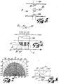
- Figure 2 is a cross-sectional view of a tube which has a symmetrical triangular cross-section and which is intended to transport air-borne particles.
- Detector units 101, 102 and 103 are positioned in each of the three corners of the triangle.
- Figure 3 illustrates a tube 50 of circular cross-section in which detector units 104, 105, 106 and 107 are positioned symmetrically with one another in direct opposite relationship. It will be understood that three detector units or more than four detector units may be used.
- Figure 4 is a cross-sectional view of a four-cornered tube in which detector units 108, 109, 110 and 111 are placed in respective corners.
- the detector units In the case of the Figure 4 embodiment, it is possible to place the detector units centrally with a sensing lobe of 180° for the side parts 112, 113, 114 and 115.
- the positioning of the detector units will depend on the application concerned.
- Figure 5 is a cross-sectional view of an arrangement according to Figure 3, in which the circular tube 50 has been cut through so that only the detector units 104, 106 and 107 can be seen.
- each of the detector units is covered with a protective screen which includes a plurality of slots s1, s2, s3, ..., s7, for instance seven, where each individual slot extends in a plane perpendicular to the transport direction.
- respective first slots s1 positioned upstream of the transport direction P extend in a first plane 51, while respective second slots s2 extend in a second plane 52 which is parallel with the first plane, and so on, up to a plane 57.
- Figure 6 is intended to illustrate that a particle of elevated temperature will first pass (as p1) the plane 51 and therewith initiate in the detector unit 104 a pulse which is associated with said plane 51. A signal of corresponding value is obtained in the detector unit 104 as the same particle passes the next point (as p2).
- a particle having a sufficient energy content will initiate a total of seven pulses as it passes through the planes 51-57 in the conduit 50.
- a specific calculation is required to calculate and evaluate the result obtained from the indications given by the different detector units.
- an adapted calculation is made of each of the signals received from the detectors, so as to be able to assess the instantaneous energy content of said particle.
- Figure 8 illustrates a plane which extends between two detector units, such as the detector units 105 and 107 in Figure 3.
- the curve 107' is intended to illustrate the intensity of the light from a particle in dependence on its distance from the detector unit 107
- the curve 105' is intended to illustrate the intensity of the light from the same particle in dependence on the distance from the detector unit 105.
- a particle (P) does not contain sufficient energy to trigger and activate the extinguishing equipment, but that it would cause the extinguishing equipment to be activated if the particle should come very close to the detector unit 107.
- the particle generates in the region 71 a signal which is restricted by the level 72 in the detector unit 107, but the value 105a is obtained in the detector unit 105.
- the calculating circuit inhibits the signal from the detector unit 107 (the detector unit 107 is saturated) and bases its calculations on signals from the detector unit 105 and is able to evaluate the energy content of the particle in accordance with the distance between the two detector units 105 and 107.
- the signals from the two detector units will be equal to one another and can be added together.
- the addition or the mean value formed will result in a value which lies beneath the limit 72.
- the level 72 can be raised and lowered and the curves 105' and 107' can be varied in accordance with preset limit values.
- the signal contributions from the detector units 104 and 106 can be considered to be constant within the region 73 and shall either be added together or a mean value formed with the values of remaining signals.
- the signal information delivered by remaining detector units shall be processed. If two or more saturation states are indicated, it shall be assumed that the maximum level has been reached.
- the aforedescribed detector arrangement may be used advantageously in a preventive safety system of the kind defined in a Patent Application entitled “Preventive Safety System” filed at the same time as the present Application. and having the European Patent Application Serial Number 94929707.1. It will be understood that the invention is not restricted to the aforedescribed and illustrated exemplifying embodiment thereof and that modifications can be made within the scope of the inventive concept as defined in the following Claims.
Landscapes
- Health & Medical Sciences (AREA)
- Public Health (AREA)
- Business, Economics & Management (AREA)
- Emergency Management (AREA)
- Fire-Detection Mechanisms (AREA)
- Measuring Temperature Or Quantity Of Heat (AREA)
- Fire-Extinguishing By Fire Departments, And Fire-Extinguishing Equipment And Control Thereof (AREA)
- Fire Alarms (AREA)
- Processes For Solid Components From Exhaust (AREA)
- Investigating Or Analysing Biological Materials (AREA)
- Processes Of Treating Macromolecular Substances (AREA)
- Geophysics And Detection Of Objects (AREA)
- Sampling And Sample Adjustment (AREA)
Abstract
Description
- The present invention relates to a detector arrangement, which functions to detect those particles in a stream of loose particles or loosely-formed material that have such a high temperature and/or such a high energy content as to constitute an incitement to fire or explosion in a downstream particle-collecting risk zone.
- By loose material is meant all types of material that can be transported with the aid of a gas or gas mixture, normally air, in which the particles of material are spaced from one another.
- Material of the kind meant here may consist in extremely fine, dust-like particles. The material may also consist in powder or granular particles, and will also include wood chips, pellets, straw and like transportable materials.
- The inventive detector arrangement is intended for use in a preventive safety system that can be used in a process in which loose process material is produced in a first unit and transported therefrom to a receiving, second unit, and in which the treatment to which the material is subjected in the first unit can result in individual particles or several particles being heated to a temperature which is sufficiently high to initiate a fire and/or an explosion within at least the second part or unit of the system, wherein as the loose material is transported from the first unit to the second unit it will pass through a stabilizing zone or disturbance zone, a high-temperature particle indicating zone, an effectuating zone, and a risk zone located in the proximity of or in the second unit.
- The stabilizing zone is intended for particles of low energy content which do not constitute a fire risk or explosion risk within the downstream zones, and particularly in the risk zone. The stabilizing zone is effective in reducing the energy content of such particles so that they will not be indicated in the indicating zone located immediately downstream of the stabilizing zone.
- The indicating zone includes one or more detector units which are intended to indicate the presence of hazardous particles, whose energy content is likely to cause a fire in the downstream zones, and then particularly in the risk zone. The detector units coact with an indicating and activating unit, such that sensing of the presence of hazardous particles will result in the activation of a device or an arrangement which delivers an extinguishing agent and/or which functions to remove particles from the system and which is included in the extinguishing zone.
- The indicating zone is followed by an effectuating zone, whose length is adapted so that the device activated within the extinguishing zone will have time to effectuate an extinguishing barrier before or when the hazardous particle reaches said zone.
- The extinguishing zone may have the form of a valve which functions to deflect a particle collection containing said hazardous particles from the transportation path leading to the risk zone.
- A preventive safety system of the aforedefined kind is known from US-A-5 193 622 and is marketed by Firefly AB, Huddinge, Sweden. This preventive safety system being intended to indicate the presence of sparks and glowing particles and to apply extinguishing or smothering means so that glowing particles will not reach a downstream process unit, such as a filter, a silo or like device, or a risk zone, in which fire and/or an explosion might otherwise occur.
- The preventive safety system utilizes different detector arrangements or systems for sensing the aforesaid particles.
- In said detector arrangements, that are pertinent to the present application, and also similar preventive arrangements the sensors used, in industrial processes, react too slowly to limit the extent to which damage is caused.
- It is thus known to utilize temperature sensors, although practical experiences have shown that such sensors often remain inactive until a fire has actually started.
- It is true that flame detectors are sensitive to small flames, but such detectors react much too late and cannot therefore be used in a preventive safety system.
- It is also known to use pressure detectors or sensors which are highly sensitive and operate with small time constants. These sensors, however, normally require an initial explosion or a fire before they are able to react.
- It is also known to use a detector arrangement which is able to indicate the presence of particles having a temperature down to 400°C.
- Practical experiences indicate that particles transported in a transportation path and having a temperature range slightly above 400°C will represent a risk of fire and explosion in different process plants in which combustible, finely-divided material is transported with the aid of a gas or gas mixture, such as an air stream, for instance.
- The following patent publications also form a part of the prior art.
- Patent publication DE-A-2 704 296 discloses an arrangement adapted to detect particles that might cause a fire or explosion, and has been used as the most relevant prior art forming the preamble of
claim 1 in the present application. - This publication discloses that a detector is positioned behind a window through which it can view into the transportation path in order for it not to restrict the flow of material through the transportation path.
- A test-lamp is positioned behind a window opposite to the window of the detector, through which the visibility for the detector through the window can be controlled.
- It is also disclosed that two detectors and two test lamps can be used, where the second detector is positioned next to or adjacent to the first test-lamp and the second test lamp is positioned next to or adjacent to the first detector.
- The two detectors are positioned so that each opposite arranged test-lamp is within their respective viewing fields, or sensing lobes, and so that their viewing fields together completely covers a cross section of the transportation path.
- Patent publication US-A-5 193 622 discloses a system where a detector is used to detect hot particles in a pipeline as a part of a device for eliminating fire risk.
- Patent publication SU-A-1 729 528 discloses a detector arrangement whereby at least two circumferential distributed detector units are provided to detect particles in a transport duct.
- The primary object of the present invention is to further improve such known detector arrangements which are constructed to indicate the presence of particles that have a temperature somewhat above 400°C and therewith enable such a detector arrangement to be included in a preventive safety system of the aforesaid kind. It will be seen in this regard that a technical problem exists in realizing the advantages that the afforded when at least two detector units within said detector arrangement have sensing lobes which cover a cross-section of the transportation path and to evaluate the energy content of an indicated particle to a high degree of accuracy in response to received signals, irrespective of the orientation within said cross-section and while taking into account, i.e. observing, the distance from respective detector units.
- It will also be seen that a technical problem is one of realizing the significance of adapting an indicating and activating unit to evaluate the intensity sensed by each of these detector units, and to coordinate the received intensity-dependent signals so as to enable the likelihood of the particles to initiate a fire and/or explosion in a downstream risk zone to be calculated and established.
- It will also be seen that a technical problem resides in the significance of arranging the detector units diametrically on the inner peripheral surface of a material transporting tube of circular cross-section, or to arrange said detector units uniformly around said inner tube periphery, and also to realize the significance of the number and orientation of the detector units used.
- It will also be seen that another technical problem is one of realizing the significance of placing the detector units opposite to one another around the inner peripheral surface of a tube that has an angular cross-section, and to realize the significance of placing the detector units in the corners of said cross-section.
- Another technical problem is one of realizing the significance of arranging the detector units symmetrically and in mutually opposed relationship around the inner peripheral surface of a tube of square or rectangular cross-section, and to realize for which applications the detector units shall be corner-related.
- A technical problem is also one of realizing that the intensity-dependent signals shall be fully or partially summatable and/or mean-value forming with a correction factor, and capable of being evaluated in a comparison circuit in order to establish whether or not the received signals exceed a specific value, and in another circuit evaluate the value on the basis of which an activation signal is sent to appropriate extinguishing equipment.
- It will be understood that a detector unit may be given a sensing or detecting angle of about 180° and have a semicircular sensing lobe.
- Another technical problem resides in realizing the significance of covering each detector unit with a protective cover, which includes a number of mutually adjacent slots which extend perpendicularly or essentially perpendicularly to the feed direction of the material, wherein all detector units are coordinated around one and the same transverse plane through the transportation path.
- With the intention of solving one or more of the aforesaid technical problems, there is proposed in accordance with the present invention a detector arrangement, which may be included advantageously in a preventive safety system defined in the introduction, having light-sensitive means in the form of phototransistors and associated sensing circuits for detecting high-energy particles, such as particles having a temperature above 400°C as stated in the preamble of
claim 1. - In accordance with the invention, the inventive detector arrangement includes at least two detector units arranged in a mannes stated in the characterizing part of
claim 1. - Preferred embodiments, which fall within the scope of the inventive concept, are stated in the subclaims
- Those advantages which can be considered particularly characteristic of an inventive detector arrangement, and particularly when the arrangement is included in a preventive safety system, reside in the provision of conditions which enable two or more detector units to ascertain the energy content of passing particles more accurately than was earlier possible, irrespective of the position of the particles within the cross-section, by virtue of sensing and/or detecting one such particle simultaneously in each of the detector units, wherein the energy content of the particle is calculated on the basis of the particle intensity signal delivered to each of the detector units.
- An exemplifying embodiment of an inventive detector arrangement at present preferred will now be described in more detail with reference to the accompanying drawing, and also with reference to an application of the detector arrangement in a preventive safety system, in which;
- Figure 1
- is a block schematic which illustrates generally a processing plant in which a detector arrangement is used, said arrangement being used in an indicating zone followed by an activating unit;
- Figure 2
- is a cross-sectional view of a transport conduit in the form of a three-walled tube part, in which a detector unit is positioned in each of the three corners of said tube;
- Figure 3
- illustrates a transport conduit of a circular cross-section in which four detector units are positioned symmetrically;
- Figure 4
- illustrates a tube of square cross-section with a detector unit positioned in each of the four corners;
- Figure 5
- is a cross-sectional view of the tube shown in Figure 3, and illustrates the orientation of the detector units;
- Figure 6
- illustrates an inventive principle of evaluating a high-temperature particle, which passes each of the detector units;
- Figure 7
- is a sensitivity diagram relating to a used detector unit, with overlapping phototransistors; and
- Figure 8
- illustrates the variation in the intensity of a particle at different distances from a detector unit and those considerations that are necessary in evaluating the energy content of the particle at different positions in said cross-section.
- Figure 1 illustrates a preventive safety system which can be used within a process, an industrial process, in which loosely-formed process material is produced within a
first unit 1 and can be transported to a receiving,second unit 2, by means of a transportation system or a conveyor path 3. - The invention is based on the assumption that material treated in the
unit 1 will produce individual particles or several particles which are heated to a temperature at which the particle or particles is/are liable to initiate fire and/or explosion in the system. One example in this regard is the disintegration of paper pulp which enters amill 1 in the direction of the arrow 4 and from which the ultimate cellulose fluff is transported to thesecond unit 2, in the form of a silo, on a conveyor path 3, which includes aconduit system 7, 8, 9 with the aid of an airstream 6. Disintegration of the paper pulp in theunit 1 may result in individual particles or several discrete particles being heated to a temperature which is sufficiently high to cause a fire and/or explosion at least within the second part orsecond unit 2, and also within the particle transportation system 3. - Although the exemplifying embodiment is described with reference to the disintegration of paper pulp which is transported to a silo with the aid of an air stream, it will be obvious that the inventive concept can also be applied in other fields and for other purposes.
- Another requirement is that the particles resulting from said disintegration are transported as loose material by a gas or gas mixture, normally air.
- Another requirement is that the nature of the treatment carried out in the
unit 1 is such as to be liable to produce particles whose heat content can constitute a risk of fire in the conduit system or in a storage space, i.e. in the so-called risk zone. - The transportation system 3, by means of which the loosely-formed material exiting in the
conduit 5 is transported between thefirst unit 1 and thesecond unit 2, includes, among other things, a stabilizingzone 7, an indicating zone 8, which functions to indicate hazardous high-temperature particles, and an extinguishing zone 9, which precedes the second unit or risk zone (2). - The indicating zone 8 includes initially a plurality of known detector units 10, for instance of the kind described and illustrated in the Swedish Published Specification 364 588 (corresponding to US-A-3 824 392, or other types of sensors that are able to detect the presence of such particles. (See figure 7)
- Several detector units 10 are able to coact with an indicating and activating
unit 12 via aline 11. - A high-temperature particle indicated by a detector unit 10 will result in that the
unit 12 activates adevice 15 which is associated with the extinguishing zone 9 and which delivers an extinguishing agent and/or removes the hazardous high-temperature particles. - In accordance with the invention, the detection-dependent intensity sensed in one or more detector units 10 can be evaluated in a
circuit 16 included in the indicating and activatingunit 12, and one of several available, indicated and suitable measures or procedures can be activated by a calculatingcircuit 17 through the medium of a circuit 18. - The measure or procedure activated in this way may include one of a number of available devices, such as one of three
devices 19, 20 and 21, depending on the nature of the activation signal on thelines - Alternatively, one and the same device can be used to a greater or a lesser extent, by modifying the signal on one of the lines.
- The invention also provides the possibility of programming the calculating
circuit 17 so that the measure or procedure to be taken will be chosen by the circuit in accordance with the nature of the process, which can be loaded through acircuit 25 coupled to theunit 12. - In this regard, the measure or procedure chosen may constitute activation of a valve which is mounted in the conduit section 9 and which functions to deflect a particle collection which includes said hazardous particles.
- The detector units 10 are placed at a distance from the
first unit 1 such that generated particles of low energy contents will pass respective detector units without initiating activation of theunit 12 and therewith without initiating a safety measure or procedure via the unit 18. - The aforementioned safety measures or safety procedures may also include the activation of the whole of a water-based extinguishing system or of solely parts of said system.
- In this case, the calculating
unit 17 will select a safety measure or procedure and also the duration over which the safety measure or procedure shall remain in effect, in a simple programmable manner. - The
unit 12 may also be programmed via a circuit 26 for the purpose of taking into account process internal conditions, such as the nature of the chosen material, a necessary time delay depending on the instant speed at which material is transported and where the instant speed can be evaluated by asensor 10a and a signal corresponding to this speed is sent to thecircuit 16 on aline 11a and further to thecircuit 17. - The
unit 12 may also be programmed to take into account the construction and method of operation of the extinguishing equipment, so that the extinguishing zone will become active immediately before a hazardous particle or hazardous particles enters or enter said zone. - Figure 2 is a cross-sectional view of a tube which has a symmetrical triangular cross-section and which is intended to transport air-borne particles.
Detector units - Figure 3 illustrates a
tube 50 of circular cross-section in whichdetector units - Figure 4 is a cross-sectional view of a four-cornered tube in which
detector units - In the case of the Figure 4 embodiment, it is possible to place the detector units centrally with a sensing lobe of 180° for the
side parts - Figure 5 is a cross-sectional view of an arrangement according to Figure 3, in which the
circular tube 50 has been cut through so that only thedetector units - An important feature of the present invention is that each of the detector units is covered with a protective screen which includes a plurality of slots s1, s2, s3, ..., s7, for instance seven, where each individual slot extends in a plane perpendicular to the transport direction.
- For instance, respective first slots s1 positioned upstream of the transport direction P extend in a
first plane 51, while respective second slots s2 extend in a second plane 52 which is parallel with the first plane, and so on, up to a plane 57. - Figure 6 is intended to illustrate that a particle of elevated temperature will first pass (as p1) the
plane 51 and therewith initiate in the detector unit 104 a pulse which is associated with saidplane 51. A signal of corresponding value is obtained in thedetector unit 104 as the same particle passes the next point (as p2). - Thus, a particle having a sufficient energy content will initiate a total of seven pulses as it passes through the planes 51-57 in the
conduit 50. - A specific calculation is required to calculate and evaluate the result obtained from the indications given by the different detector units. Thus, in order to compensate as best as possible for the fact that the light intensity of a particle will decrease with the square of the distance from a detector and increase with the square of the distance towards a detector, an adapted calculation is made of each of the signals received from the detectors, so as to be able to assess the instantaneous energy content of said particle.
- Figure 8 illustrates a plane which extends between two detector units, such as the
detector units - The curve 107' is intended to illustrate the intensity of the light from a particle in dependence on its distance from the
detector unit 107, and the curve 105' is intended to illustrate the intensity of the light from the same particle in dependence on the distance from thedetector unit 105. - It is assumed that a particle (P) does not contain sufficient energy to trigger and activate the extinguishing equipment, but that it would cause the extinguishing equipment to be activated if the particle should come very close to the
detector unit 107. - The particle generates in the region 71 a signal which is restricted by the level 72 in the
detector unit 107, but thevalue 105a is obtained in thedetector unit 105. - In this case, the calculating circuit inhibits the signal from the detector unit 107 (the
detector unit 107 is saturated) and bases its calculations on signals from thedetector unit 105 and is able to evaluate the energy content of the particle in accordance with the distance between the twodetector units - If it is assumed that a particle is located in the middle (Pm), the signals from the two detector units will be equal to one another and can be added together. The addition or the mean value formed will result in a value which lies beneath the limit 72.
- This evaluation is made within the
region 73. - The level 72 can be raised and lowered and the curves 105' and 107' can be varied in accordance with preset limit values.
- Although not shown, further levels shall be introduced, so as to be able to select activity modes.
- The signal contributions from the
detector units region 73 and shall either be added together or a mean value formed with the values of remaining signals. - Thus, as soon as one of the detector units indicates "saturated", the signal information delivered by remaining detector units shall be processed. If two or more saturation states are indicated, it shall be assumed that the maximum level has been reached.
- Calculating circuits which take these circumstances into account can be constructed without requiring work of an inventive nature.
- It is also feasible within the scope of the invention that when a particle has passed through a selected number of planes, such as the
planes 51, 52 and 53, and each of these planes has indicated a sufficiently high signal to activate adevice 15, which belongs to the extinguishing zone and which functions to deliver an extinguishing agent and/or functions to remove particles, the device will be activated after a specific number of clear indications have been given, for instance three indications. - The aforedescribed detector arrangement may be used advantageously in a preventive safety system of the kind defined in a Patent Application entitled "Preventive Safety System" filed at the same time as the present Application. and having the European Patent Application Serial Number 94929707.1. It will be understood that the invention is not restricted to the aforedescribed and illustrated exemplifying embodiment thereof and that modifications can be made within the scope of the inventive concept as defined in the following Claims.
Claims (7)
- A detector arrangement which may be included in a preventive safety system that can be used within a process in which loosely-formed process material is produced in a first unit (1) and transported to a receiving, second unit (2), wherein the treatment to which the material is subjected in said first unit (1) is liable to produce one or more discrete particles which have a temperature sufficiently high to initiate fire and/or explosion within at least the second part or unit, wherein the necessary transportation of the loose material between the first unit (2) and the second unit (2) is effected along a path (3) which includes a stabilizing zone (7), a high-temperature particle indicating zone (8), and an extinguishing zone (9), wherein the detector arrangement includes two or more detector units adapted to detect said particles within said indicating zone (8), wherein the detector units (105, 107) coact with an indicating and activating unit (12) such that indication by the detector units (105, 107) of the presence of a high-temperature particle in said indicating zone (8) said indicating and activating unit (12) will activate a device (15) which is associated with the extinguishing zone (9) and which functions to deliver an extinguishing agent and/or to remove particles, wherein the sensing lobes of the at least two detector units (105, 107) cover a cross-section of the transportation path, characterized in that the detector units are arranged such that a particle is within the sensing lobe of at least two detector units covering a cross-section; and in that the indicating and activating unit (12) is adapted to evaluate the sensed intensity from each of said detector units (105, 107) and to coordinate received intensity-dependent signals so as to calculate and establish on the basis thereof the liability of the particle to initiate fire and/or explosion.
- An arrangement according to Claim 1, characterized in that the detector units (104, 105, 106, 107) are arranged diametrically on an inner peripheral surface of a tube of circular cross-section, or are arranged uniformly around said surface.
- An arrangement according to Claim 1, characterized in that the detector units (101, 102, 103) are arranged opposite one another on an inner peripheral surface of a tube having an angled cross-section, said detector units being placed in the corners of said cross-section.
- An arrangement according to Claim 1, characterized in that the detector units (108, 109, 110, 111) are arranged symmetrically and opposite one another around an inner peripheral surface of a tube having a square or rectangular cross-section.
- An arrangement according to Claim 1, characterized in that the intensity-dependent signals are fully or partially summatable and/or mean-value forming and/or inhibited and can be evaluated in a comparison circuit (16) in order to ascertain whether or not the received signals exceed a given value, this value being evaluated in another circuit (17) for the purpose of choosing a degree of activation on the basis of said value.
- An arrangement according to Claim 1, characterized in that each detector unit has a sensing angle of about 180°.
- An arrangement according to Claim 1, characterized in that each detector unit (104) is covered with a protective screen which includes a plurality of mutually adjacent slots S1, S2, S3, ..., S7) which are orientated in a direction at right angles or essentially at right angles to the direction of movement of said material.
Applications Claiming Priority (3)
| Application Number | Priority Date | Filing Date | Title |
|---|---|---|---|
| SE9303306 | 1993-10-08 | ||
| SE9303306A SE501123C2 (en) | 1993-10-08 | 1993-10-08 | detector arrangement |
| PCT/SE1994/000908 WO1995010330A1 (en) | 1993-10-08 | 1994-10-03 | Device for particles detection in a pipeline |
Publications (2)
| Publication Number | Publication Date |
|---|---|
| EP0789607A1 EP0789607A1 (en) | 1997-08-20 |
| EP0789607B1 true EP0789607B1 (en) | 1999-06-16 |
Family
ID=20391359
Family Applications (1)
| Application Number | Title | Priority Date | Filing Date |
|---|---|---|---|
| EP94929708A Expired - Lifetime EP0789607B1 (en) | 1993-10-08 | 1994-10-03 | Device for particles detection in a pipeline |
Country Status (10)
| Country | Link |
|---|---|
| US (1) | US5749420A (en) |
| EP (1) | EP0789607B1 (en) |
| JP (1) | JP3568205B2 (en) |
| CN (1) | CN1066970C (en) |
| AT (1) | ATE181247T1 (en) |
| AU (1) | AU680949B2 (en) |
| CA (1) | CA2173498C (en) |
| DE (1) | DE69419182T2 (en) |
| SE (1) | SE501123C2 (en) |
| WO (1) | WO1995010330A1 (en) |
Families Citing this family (6)
| Publication number | Priority date | Publication date | Assignee | Title |
|---|---|---|---|---|
| SE501122C2 (en) * | 1993-10-08 | 1994-11-21 | Firefly Ab | Preventive protection system |
| DE29612431U1 (en) * | 1996-07-17 | 1997-11-20 | Fagus-Grecon Greten Gmbh & Co Kg, 31061 Alfeld | Extinguishing system |
| SE515579C2 (en) * | 1998-12-29 | 2001-09-03 | Firefly Ab | Detector arrangement for detecting particles that may cause fire or explosion in a particle stream |
| SE516700C2 (en) * | 1999-06-07 | 2002-02-12 | Firefly Ab | detector arrangement |
| SE541656C2 (en) | 2018-02-23 | 2019-11-19 | Firefly Ab | Monitoring of particle temperature trends |
| SE541639C2 (en) | 2018-02-23 | 2019-11-19 | Firefly Ab | Determination of risk level for particles |
Family Cites Families (4)
| Publication number | Priority date | Publication date | Assignee | Title |
|---|---|---|---|---|
| SE364588B (en) * | 1972-04-24 | 1974-02-25 | Pak Construction Ab | |
| US3909954A (en) * | 1974-04-03 | 1975-10-07 | Marc K Zoukourian | Device for prevention and protection against fire and explosion in the lines of the treatment of inflammable comminuted products |
| SE455471B (en) * | 1985-11-29 | 1988-07-18 | Firefly Ab | DEVICE FOR PREVENTING RISK OF FIRE BECAUSE OF BURNING OR GLASSING PARTICLES IN A PIPE PIPE |
| SU1729528A1 (en) * | 1990-08-13 | 1992-04-30 | Государственный оптический институт им.С.И.Вавилова | Device for detection of smouldering particles in pneumatic transport |
-
1993
- 1993-10-08 SE SE9303306A patent/SE501123C2/en not_active IP Right Cessation
-
1994
- 1994-10-03 AU AU78663/94A patent/AU680949B2/en not_active Expired
- 1994-10-03 AT AT94929708T patent/ATE181247T1/en active
- 1994-10-03 CN CN94194382A patent/CN1066970C/en not_active Expired - Lifetime
- 1994-10-03 WO PCT/SE1994/000908 patent/WO1995010330A1/en not_active Ceased
- 1994-10-03 CA CA002173498A patent/CA2173498C/en not_active Expired - Lifetime
- 1994-10-03 DE DE69419182T patent/DE69419182T2/en not_active Expired - Lifetime
- 1994-10-03 US US08/624,486 patent/US5749420A/en not_active Expired - Lifetime
- 1994-10-03 JP JP51165995A patent/JP3568205B2/en not_active Expired - Lifetime
- 1994-10-03 EP EP94929708A patent/EP0789607B1/en not_active Expired - Lifetime
Also Published As
| Publication number | Publication date |
|---|---|
| DE69419182T2 (en) | 1999-12-23 |
| SE9303306L (en) | 1994-11-21 |
| AU7866394A (en) | 1995-05-04 |
| AU680949B2 (en) | 1997-08-14 |
| EP0789607A1 (en) | 1997-08-20 |
| DE69419182D1 (en) | 1999-07-22 |
| CN1136783A (en) | 1996-11-27 |
| CA2173498A1 (en) | 1995-04-20 |
| JPH09504714A (en) | 1997-05-13 |
| CA2173498C (en) | 2005-11-29 |
| WO1995010330A1 (en) | 1995-04-20 |
| SE9303306D0 (en) | 1993-10-08 |
| SE501123C2 (en) | 1994-11-21 |
| CN1066970C (en) | 2001-06-13 |
| JP3568205B2 (en) | 2004-09-22 |
| ATE181247T1 (en) | 1999-07-15 |
| US5749420A (en) | 1998-05-12 |
Similar Documents
| Publication | Publication Date | Title |
|---|---|---|
| US8791826B2 (en) | Method and device for fire detection in enclosed environments | |
| US3867640A (en) | Dust sampling system | |
| EP0789607B1 (en) | Device for particles detection in a pipeline | |
| EP0789606B1 (en) | Device for preventing the risk of fire due to burning or glowing particles in a pipeline | |
| JP6020104B2 (en) | Fire protection equipment for bulky waste treatment facilities | |
| US3772958A (en) | Apparatus for ammunition disposal | |
| US6732810B1 (en) | Detector system for detecting glowing particles | |
| WO2000074786A1 (en) | A detector arrangement for detection of fire risk in a process plant | |
| US5103916A (en) | Differential fire and explosion protection system | |
| Bulig | Protecting food manufacturing processes from dust explosions | |
| CN221637201U (en) | Fire control unit is used in broken process of useless fabrics | |
| Taveau et al. | Chemical explosion isolation applied to small mills | |
| US3771472A (en) | Apparatus for the measurement of dust content a gas stream | |
| CA2173496A1 (en) | Device for preventing the risk of fire due to burning or glowing particles in a pipeline | |
| CN111771107B (en) | Determine the risk level of particles | |
| US20200386622A1 (en) | Monitoring of particle temperature trends | |
| Moore | Industrial explosion protection-venting or suppression? | |
| PL70293Y1 (en) | Intrinsically safe numerically controlled machining device |
Legal Events
| Date | Code | Title | Description |
|---|---|---|---|
| PUAI | Public reference made under article 153(3) epc to a published international application that has entered the european phase |
Free format text: ORIGINAL CODE: 0009012 |
|
| 17P | Request for examination filed |
Effective date: 19960426 |
|
| AK | Designated contracting states |
Kind code of ref document: A1 Designated state(s): AT BE CH DE DK ES FR GB GR IE IT LI LU MC NL PT |
|
| 17Q | First examination report despatched |
Effective date: 19980423 |
|
| GRAG | Despatch of communication of intention to grant |
Free format text: ORIGINAL CODE: EPIDOS AGRA |
|
| GRAG | Despatch of communication of intention to grant |
Free format text: ORIGINAL CODE: EPIDOS AGRA |
|
| GRAH | Despatch of communication of intention to grant a patent |
Free format text: ORIGINAL CODE: EPIDOS IGRA |
|
| GRAH | Despatch of communication of intention to grant a patent |
Free format text: ORIGINAL CODE: EPIDOS IGRA |
|
| GRAA | (expected) grant |
Free format text: ORIGINAL CODE: 0009210 |
|
| AK | Designated contracting states |
Kind code of ref document: B1 Designated state(s): AT BE CH DE DK ES FR GB GR IE IT LI LU MC NL PT |
|
| PG25 | Lapsed in a contracting state [announced via postgrant information from national office to epo] |
Ref country code: NL Free format text: LAPSE BECAUSE OF FAILURE TO SUBMIT A TRANSLATION OF THE DESCRIPTION OR TO PAY THE FEE WITHIN THE PRESCRIBED TIME-LIMIT Effective date: 19990616 Ref country code: IT Free format text: LAPSE BECAUSE OF FAILURE TO SUBMIT A TRANSLATION OF THE DESCRIPTION OR TO PAY THE FEE WITHIN THE PRE;WARNING: LAPSES OF ITALIAN PATENTS WITH EFFECTIVE DATE BEFORE 2007 MAY HAVE OCCURRED AT ANY TIME BEFORE 2007. THE CORRECT EFFECTIVE DATE MAY BE DIFFERENT FROM THE ONE RECORDED.SCRIBED TIME-LIMIT Effective date: 19990616 Ref country code: GR Free format text: LAPSE BECAUSE OF NON-PAYMENT OF DUE FEES Effective date: 19990616 Ref country code: ES Free format text: THE PATENT HAS BEEN ANNULLED BY A DECISION OF A NATIONAL AUTHORITY Effective date: 19990616 |
|
| REF | Corresponds to: |
Ref document number: 181247 Country of ref document: AT Date of ref document: 19990715 Kind code of ref document: T |
|
| RIN1 | Information on inventor provided before grant (corrected) |
Inventor name: JANSSON, LENNART, CARL, ERIK |
|
| REG | Reference to a national code |
Ref country code: CH Ref legal event code: EP |
|
| REF | Corresponds to: |
Ref document number: 69419182 Country of ref document: DE Date of ref document: 19990722 |
|
| ET | Fr: translation filed | ||
| REG | Reference to a national code |
Ref country code: IE Ref legal event code: FG4D Free format text: GERMAN |
|
| PG25 | Lapsed in a contracting state [announced via postgrant information from national office to epo] |
Ref country code: PT Free format text: LAPSE BECAUSE OF FAILURE TO SUBMIT A TRANSLATION OF THE DESCRIPTION OR TO PAY THE FEE WITHIN THE PRESCRIBED TIME-LIMIT Effective date: 19990916 Ref country code: DK Free format text: LAPSE BECAUSE OF FAILURE TO SUBMIT A TRANSLATION OF THE DESCRIPTION OR TO PAY THE FEE WITHIN THE PRESCRIBED TIME-LIMIT Effective date: 19990916 |
|
| REG | Reference to a national code |
Ref country code: CH Ref legal event code: NV Representative=s name: ARDIN & CIE S.A. |
|
| PG25 | Lapsed in a contracting state [announced via postgrant information from national office to epo] |
Ref country code: LU Free format text: LAPSE BECAUSE OF NON-PAYMENT OF DUE FEES Effective date: 19991003 Ref country code: IE Free format text: LAPSE BECAUSE OF NON-PAYMENT OF DUE FEES Effective date: 19991003 |
|
| NLV1 | Nl: lapsed or annulled due to failure to fulfill the requirements of art. 29p and 29m of the patents act | ||
| BECA | Be: change of holder's address |
Free format text: 19990616 *FIREFLY A.B.:BOX 47134, 100 74 STOCKHOLM |
|
| PLBE | No opposition filed within time limit |
Free format text: ORIGINAL CODE: 0009261 |
|
| STAA | Information on the status of an ep patent application or granted ep patent |
Free format text: STATUS: NO OPPOSITION FILED WITHIN TIME LIMIT |
|
| PG25 | Lapsed in a contracting state [announced via postgrant information from national office to epo] |
Ref country code: MC Free format text: LAPSE BECAUSE OF NON-PAYMENT OF DUE FEES Effective date: 20000430 |
|
| 26N | No opposition filed | ||
| REG | Reference to a national code |
Ref country code: IE Ref legal event code: MM4A |
|
| REG | Reference to a national code |
Ref country code: GB Ref legal event code: IF02 |
|
| PGFP | Annual fee paid to national office [announced via postgrant information from national office to epo] |
Ref country code: AT Payment date: 20131028 Year of fee payment: 20 Ref country code: DE Payment date: 20131022 Year of fee payment: 20 Ref country code: GB Payment date: 20131023 Year of fee payment: 20 Ref country code: FR Payment date: 20131031 Year of fee payment: 20 Ref country code: BE Payment date: 20131022 Year of fee payment: 20 Ref country code: CH Payment date: 20131015 Year of fee payment: 20 |
|
| REG | Reference to a national code |
Ref country code: DE Ref legal event code: R071 Ref document number: 69419182 Country of ref document: DE |
|
| REG | Reference to a national code |
Ref country code: CH Ref legal event code: PL |
|
| REG | Reference to a national code |
Ref country code: GB Ref legal event code: PE20 Expiry date: 20141002 |
|
| REG | Reference to a national code |
Ref country code: AT Ref legal event code: MK07 Ref document number: 181247 Country of ref document: AT Kind code of ref document: T Effective date: 20141003 |
|
| PG25 | Lapsed in a contracting state [announced via postgrant information from national office to epo] |
Ref country code: GB Free format text: LAPSE BECAUSE OF EXPIRATION OF PROTECTION Effective date: 20141002 |