EP0789101A2 - A method of manufacturing a filter material - Google Patents
A method of manufacturing a filter material Download PDFInfo
- Publication number
- EP0789101A2 EP0789101A2 EP97200360A EP97200360A EP0789101A2 EP 0789101 A2 EP0789101 A2 EP 0789101A2 EP 97200360 A EP97200360 A EP 97200360A EP 97200360 A EP97200360 A EP 97200360A EP 0789101 A2 EP0789101 A2 EP 0789101A2
- Authority
- EP
- European Patent Office
- Prior art keywords
- filaments
- filter web
- filter
- strips
- narrow strips
- Prior art date
- Legal status (The legal status is an assumption and is not a legal conclusion. Google has not performed a legal analysis and makes no representation as to the accuracy of the status listed.)
- Withdrawn
Links
Images
Classifications
-
- B—PERFORMING OPERATIONS; TRANSPORTING
- B01—PHYSICAL OR CHEMICAL PROCESSES OR APPARATUS IN GENERAL
- B01D—SEPARATION
- B01D39/00—Filtering material for liquid or gaseous fluids
- B01D39/14—Other self-supporting filtering material ; Other filtering material
- B01D39/16—Other self-supporting filtering material ; Other filtering material of organic material, e.g. synthetic fibres
- B01D39/1607—Other self-supporting filtering material ; Other filtering material of organic material, e.g. synthetic fibres the material being fibrous
- B01D39/1623—Other self-supporting filtering material ; Other filtering material of organic material, e.g. synthetic fibres the material being fibrous of synthetic origin
-
- D—TEXTILES; PAPER
- D04—BRAIDING; LACE-MAKING; KNITTING; TRIMMINGS; NON-WOVEN FABRICS
- D04H—MAKING TEXTILE FABRICS, e.g. FROM FIBRES OR FILAMENTARY MATERIAL; FABRICS MADE BY SUCH PROCESSES OR APPARATUS, e.g. FELTS, NON-WOVEN FABRICS; COTTON-WOOL; WADDING ; NON-WOVEN FABRICS FROM STAPLE FIBRES, FILAMENTS OR YARNS, BONDED WITH AT LEAST ONE WEB-LIKE MATERIAL DURING THEIR CONSOLIDATION
- D04H1/00—Non-woven fabrics formed wholly or mainly of staple fibres or like relatively short fibres
- D04H1/40—Non-woven fabrics formed wholly or mainly of staple fibres or like relatively short fibres from fleeces or layers composed of fibres without existing or potential cohesive properties
- D04H1/44—Non-woven fabrics formed wholly or mainly of staple fibres or like relatively short fibres from fleeces or layers composed of fibres without existing or potential cohesive properties the fleeces or layers being consolidated by mechanical means, e.g. by rolling
- D04H1/46—Non-woven fabrics formed wholly or mainly of staple fibres or like relatively short fibres from fleeces or layers composed of fibres without existing or potential cohesive properties the fleeces or layers being consolidated by mechanical means, e.g. by rolling by needling or like operations to cause entanglement of fibres
-
- D—TEXTILES; PAPER
- D04—BRAIDING; LACE-MAKING; KNITTING; TRIMMINGS; NON-WOVEN FABRICS
- D04H—MAKING TEXTILE FABRICS, e.g. FROM FIBRES OR FILAMENTARY MATERIAL; FABRICS MADE BY SUCH PROCESSES OR APPARATUS, e.g. FELTS, NON-WOVEN FABRICS; COTTON-WOOL; WADDING ; NON-WOVEN FABRICS FROM STAPLE FIBRES, FILAMENTS OR YARNS, BONDED WITH AT LEAST ONE WEB-LIKE MATERIAL DURING THEIR CONSOLIDATION
- D04H13/00—Other non-woven fabrics
-
- B—PERFORMING OPERATIONS; TRANSPORTING
- B01—PHYSICAL OR CHEMICAL PROCESSES OR APPARATUS IN GENERAL
- B01D—SEPARATION
- B01D2239/00—Aspects relating to filtering material for liquid or gaseous fluids
- B01D2239/02—Types of fibres, filaments or particles, self-supporting or supported materials
- B01D2239/0216—Bicomponent or multicomponent fibres
- B01D2239/0233—Island-in-sea
-
- B—PERFORMING OPERATIONS; TRANSPORTING
- B01—PHYSICAL OR CHEMICAL PROCESSES OR APPARATUS IN GENERAL
- B01D—SEPARATION
- B01D2239/00—Aspects relating to filtering material for liquid or gaseous fluids
- B01D2239/04—Additives and treatments of the filtering material
- B01D2239/0435—Electret
-
- B—PERFORMING OPERATIONS; TRANSPORTING
- B01—PHYSICAL OR CHEMICAL PROCESSES OR APPARATUS IN GENERAL
- B01D—SEPARATION
- B01D2239/00—Aspects relating to filtering material for liquid or gaseous fluids
- B01D2239/06—Filter cloth, e.g. knitted, woven non-woven; self-supported material
- B01D2239/065—More than one layer present in the filtering material
- B01D2239/0659—The layers being joined by needling
-
- B—PERFORMING OPERATIONS; TRANSPORTING
- B01—PHYSICAL OR CHEMICAL PROCESSES OR APPARATUS IN GENERAL
- B01D—SEPARATION
- B01D2239/00—Aspects relating to filtering material for liquid or gaseous fluids
- B01D2239/06—Filter cloth, e.g. knitted, woven non-woven; self-supported material
- B01D2239/065—More than one layer present in the filtering material
- B01D2239/0681—The layers being joined by gluing
-
- B—PERFORMING OPERATIONS; TRANSPORTING
- B01—PHYSICAL OR CHEMICAL PROCESSES OR APPARATUS IN GENERAL
- B01D—SEPARATION
- B01D2239/00—Aspects relating to filtering material for liquid or gaseous fluids
- B01D2239/06—Filter cloth, e.g. knitted, woven non-woven; self-supported material
- B01D2239/069—Special geometry of layers
- B01D2239/0695—Wound layers
-
- B—PERFORMING OPERATIONS; TRANSPORTING
- B01—PHYSICAL OR CHEMICAL PROCESSES OR APPARATUS IN GENERAL
- B01D—SEPARATION
- B01D2239/00—Aspects relating to filtering material for liquid or gaseous fluids
- B01D2239/10—Filtering material manufacturing
Definitions
- the invention relates to a method for manufacturing filter material, comprising forming a non-woven filter web from electrostatically charged dielectric fibres.
- the object of the invention is to manufacture a filter material which has a uniform weight per unit area and high dimensional stability, and which exhibits a lower pressure drop over the filter material during use and is cheaper than the filter material according to EP-A-0626878.
- the method is characterized in that filaments or narrow strips are placed essentially at a distance from each other on at least one of the two sides of the filter web and fixed to the non-woven filter web.
- the filaments or strips on each side of the filter web preferably do not intersect each other or touch each other.
- this will mean that the filaments or strips run essentially parallel to each other on each side of the filter web.
- the filaments or strips prefferably be made of two components: an inner component with a relatively high melting point and an outer component with a relatively low melting point.
- the filaments or strips are consequently fixed to the filter web by means of the molten outer material.
- the filaments or strips can also be fixed to the filter material by means of glue.
- the filter web will undergo needle punching before and/or after the placing of the filaments or narrow strips.
- the stability and strength in two directions is achieved if the filaments or narrow strips are placed on the two sides of the filter web, the filaments or strips on one side of the filter web running crosswise relative to the filaments or strips on the other side of the filter web.
- the latter will preferably consist of pieces whose length is slightly greater than the width of the filter web, the ends of said pieces being glued to adhesive tapes and, after connection of the filaments or narrow strips to the filter web, the filaments or strips being severed on the inside of the tapes.
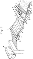
- Figure 1 shows diagrammatically and in perspective an exemplary embodiment of a device suitable for carrying out the method according to the invention.
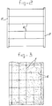
- Figure 2 shows an elevational view of a strip of filament pieces which are glued to tapes.
- Figure 3 shows filter material which has been manufactured with, inter alia, the filament pieces according to the invention shown in Figure 2.
- a web of non-woven filter material 1 is being manufactured from electrically charged dielectric fibres in a manner which is known per se on a conveyor 2.
- Said conveyor 2 conveys the material onto a conveyor 3, which leads to a needle punching device 4, in this case consisting of two rollers provided with needles.
- a needle punching device 4 in this case consisting of two rollers provided with needles.
- the filter material treated in this way is conveyed, together with a number of parallel filaments 5 which are situated at a distance from each other above the filter web and a number of parallel filaments 6 which are situated at a distance from each other below the filter web, between two calender rollers 7 and 8 heated to, for example. 60°C, where the filaments are fixed to the non-woven material by fusing.
- the filaments come from rolls 9, 10 respectively and run through holes in plates or strips 11, 12 respectively, in order to place the filaments at the correct mutual distance.
- the fusing temperature is selected at a value at which it does not cause any damage to the electrical properties of the fibres or strips.
- the non-woven filter web which has been made dimensionally stable on the top and bottom surface by the filaments fused on in this way is conveyed on a conveyor 13 to a second needle punching device 14, where approximately 100 holes per square centimetre are made in the filter material by means of needles.
- the loss of permeability, caused by the compacting of the filter material by the calender rollers, is compensated for in this way.
- the finished filter material is conveyed by way of guide rolls 15 to a drum 18, onto which said finished filter material is wound.
- the parallel filaments on one side of the filter material extend at right angles to the parallel filaments on the other side of the filter material.
- the filaments 5 on one side will extend in the direction of movement of the filter material.
- the filaments 16 on the other side are made of pieces which are slightly longer than the width of the filter material to be manufactured.
- Figure 2 shows that the ends of the filament pieces 16 are glued to tapes 17.
- the combination of filament pieces and tapes is conveyed to the nip between the calender rollers 7, 8. where the filament pieces are fused to, for example, the underside of the filter material.
- the end pieces of the filaments stuck to the tapes 17 are then cut away.
- the end product can be seen in Figure 3.
- the filter material is resistant to tensile forces both in the direction of the filaments 5 and in the direction of the filaments 6 situated at right angles thereto.
- the filaments have little or no adverse influence on the permeability of the finished filter material. Where narrow strips are used instead of filaments, the permeability will actually decrease slightly, but the result is excellent.
- the fusing of the filaments or narrow strips to the filter web could be replaced by gluing.
- the filaments or narrow strips can be made entirely of thermoplastic plastic, at least if they are made of one component and are being fused.
- Another good solution is the use of two-component filaments or strips, the inside of which is made of a material with high melting point, while a casing is made of a material with low melting point.
Landscapes
- Engineering & Computer Science (AREA)
- Textile Engineering (AREA)
- Mechanical Engineering (AREA)
- Chemical & Material Sciences (AREA)
- Chemical Kinetics & Catalysis (AREA)
- Filtering Materials (AREA)
Abstract
Description
- The invention relates to a method for manufacturing filter material, comprising forming a non-woven filter web from electrostatically charged dielectric fibres.
- Such a method is known from EP-A-0626878. In this case, in order to improve the uniformity of the filter properties, a loose, open, non-stretch reinforcing textile material (scrim) is attached, after which both the filter web and the scrim undergo needle punching. Attaching a scrim does improve the dimensional stability of the product, but the textile material increases the pressure drop over the filter and makes the end product relatively expensive.
- The object of the invention is to manufacture a filter material which has a uniform weight per unit area and high dimensional stability, and which exhibits a lower pressure drop over the filter material during use and is cheaper than the filter material according to EP-A-0626878.
- To this end, according to the invention the method is characterized in that filaments or narrow strips are placed essentially at a distance from each other on at least one of the two sides of the filter web and fixed to the non-woven filter web.
- The filaments or strips on each side of the filter web preferably do not intersect each other or touch each other.
- In general, this will mean that the filaments or strips run essentially parallel to each other on each side of the filter web.
- It is preferable for the filaments or strips to be made of two components: an inner component with a relatively high melting point and an outer component with a relatively low melting point. The filaments or strips are consequently fixed to the filter web by means of the molten outer material.
- The filaments or strips can also be fixed to the filter material by means of glue.
- In order to reduce the pressure loss as a result of compression of the filter material during the so-called calendering, the filter web will undergo needle punching before and/or after the placing of the filaments or narrow strips.
- The stability and strength in two directions is achieved if the filaments or narrow strips are placed on the two sides of the filter web, the filaments or strips on one side of the filter web running crosswise relative to the filaments or strips on the other side of the filter web.
- In order to fuse the filaments or narrow strips to the filter material, they are conveyed with the filter web into a nip between two heated calender rollers.
- In the case of a product with filaments or strips in the lengthwise direction of the web and filaments or strips crosswise thereto the latter will preferably consist of pieces whose length is slightly greater than the width of the filter web, the ends of said pieces being glued to adhesive tapes and, after connection of the filaments or narrow strips to the filter web, the filaments or strips being severed on the inside of the tapes.
- It is within the scope of the invention to place patterns of filaments or strips which intersect each other on one side or two sides of the filter web.
- The invention will now be explained in greater detail with reference to the figures.
- Figure 1 shows diagrammatically and in perspective an exemplary embodiment of a device suitable for carrying out the method according to the invention.
- Figure 2 shows an elevational view of a strip of filament pieces which are glued to tapes.
- Figure 3 shows filter material which has been manufactured with, inter alia, the filament pieces according to the invention shown in Figure 2.
- It can be seen in Figure 1 that a web of non-woven filter material 1 is being manufactured from electrically charged dielectric fibres in a manner which is known per se on a conveyor 2. Said conveyor 2 conveys the material onto a conveyor 3, which leads to a needle punching device 4, in this case consisting of two rollers provided with needles. In this needle punching device approximately 50 holes per square centimetre are made in the non-woven filter material. The filter material treated in this way is conveyed, together with a number of
parallel filaments 5 which are situated at a distance from each other above the filter web and a number of parallel filaments 6 which are situated at a distance from each other below the filter web, between two calender rollers 7 and 8 heated to, for example. 60°C, where the filaments are fixed to the non-woven material by fusing. The filaments come fromrolls 9, 10 respectively and run through holes in plates orstrips 11, 12 respectively, in order to place the filaments at the correct mutual distance. - The fusing temperature is selected at a value at which it does not cause any damage to the electrical properties of the fibres or strips.
- The non-woven filter web which has been made dimensionally stable on the top and bottom surface by the filaments fused on in this way is conveyed on a conveyor 13 to a second
needle punching device 14, where approximately 100 holes per square centimetre are made in the filter material by means of needles. The loss of permeability, caused by the compacting of the filter material by the calender rollers, is compensated for in this way. - Finally, the finished filter material is conveyed by way of guide rolls 15 to a
drum 18, onto which said finished filter material is wound. - Better dimensional stability is achieved in the filter material if the parallel filaments on one side of the filter material extend at right angles to the parallel filaments on the other side of the filter material. When this is achieved, the
filaments 5 on one side will extend in the direction of movement of the filter material. Thefilaments 16 on the other side are made of pieces which are slightly longer than the width of the filter material to be manufactured. - Figure 2 shows that the ends of the
filament pieces 16 are glued totapes 17. The combination of filament pieces and tapes is conveyed to the nip between the calender rollers 7, 8. where the filament pieces are fused to, for example, the underside of the filter material. The end pieces of the filaments stuck to thetapes 17 are then cut away. The end product can be seen in Figure 3. The filter material is resistant to tensile forces both in the direction of thefilaments 5 and in the direction of the filaments 6 situated at right angles thereto. - In all embodiments the filaments have little or no adverse influence on the permeability of the finished filter material. Where narrow strips are used instead of filaments, the permeability will actually decrease slightly, but the result is excellent.
- The fusing of the filaments or narrow strips to the filter web could be replaced by gluing. The filaments or narrow strips can be made entirely of thermoplastic plastic, at least if they are made of one component and are being fused. Another good solution is the use of two-component filaments or strips, the inside of which is made of a material with high melting point, while a casing is made of a material with low melting point.
- There is the possibility of placing the filament pieces on the filter web in the form of a zigzag pattern, successive pieces meeting at a common intersection point.
- What is essential for the end product is that the filaments or narrow strips leave the surface virtually entirely clear on both sides of the filter web.
Claims (10)
- Method for manufacturing filter material, comprising forming a non-woven filter web (1) from electrostatically charged dielectric fibres, characterized in that filaments (5, 6; 16) or narrow strips are placed essentially at a distance from each other on at least one of the two sides of the non-woven filter web and fixed to the non-woven filter web.
- Method according to Claim 1, characterized in that the filaments (5, 6; 16) or narrow strips do not intersect each other or touch each other on each side of the filter web.
- Method according to Claim 1 or 2, characterized in that the filaments (5, 6, 16) or narrow strips are fixed to the filter web by fusing.
- Method according to Claim 1 or 2, characterized in that the filaments (5, 6; 16) or narrow strips are fixed to the filter web by means of glue.
- Method according to Claim 3, characterized in that the filaments (5, 6; 16) or narrow strips are made of two components: an inner component with a relatively high melting point and an outer component with a relatively low melting point.
- Method according to one of the preceding claims, characterized in that the filter web (1) undergoes needle punching (4, 14) before and/or after the placing of the filaments (5, 6; 16) or narrow strips.
- Method according to one of the preceding claims, characterized in that the filaments or the narrow strips are placed on the two sides of the filter web, the filaments (5) or strips on one side of the filter web running crosswise relative to the filaments (16) or strips on the other side of the filter web.
- Method according to Claim 3, characterized in that the filaments (5, 6; 16) or narrow strips are conveyed together with the filter web (1) into the nip between two heated calender rollers (7, 8).
- Method according to Claim 7, characterized in that the filaments (16) or narrow strips which are to be placed at right angles to the direction of movement of the filter web (1) consist of pieces whose length is slightly greater than the width of the filter web, and in that the ends of said pieces are glued to adhesive tapes (17) and, after connection of the filaments or narrow strips to the filter web, the filaments or strips are severed on the inside of the tapes.
- Filter material manufactured according to the method of one of the preceding claims.
Applications Claiming Priority (2)
| Application Number | Priority Date | Filing Date | Title |
|---|---|---|---|
| NL1002295 | 1996-02-09 | ||
| NL1002295A NL1002295C2 (en) | 1996-02-09 | 1996-02-09 | Method for manufacturing filter material. |
Publications (2)
| Publication Number | Publication Date |
|---|---|
| EP0789101A2 true EP0789101A2 (en) | 1997-08-13 |
| EP0789101A3 EP0789101A3 (en) | 2000-05-24 |
Family
ID=19762277
Family Applications (1)
| Application Number | Title | Priority Date | Filing Date |
|---|---|---|---|
| EP97200360A Withdrawn EP0789101A3 (en) | 1996-02-09 | 1997-02-10 | A method of manufacturing a filter material |
Country Status (3)
| Country | Link |
|---|---|
| US (1) | US6017411A (en) |
| EP (1) | EP0789101A3 (en) |
| NL (1) | NL1002295C2 (en) |
Cited By (3)
| Publication number | Priority date | Publication date | Assignee | Title |
|---|---|---|---|---|
| FR2754278A1 (en) * | 1996-10-07 | 1998-04-10 | Inventa Ag | NON-WOVEN INSERTION WOVEN REINFORCED BY MULTIFILAMENT YARN AND ITS MANUFACTURING METHOD |
| EP1048887A3 (en) * | 1999-04-27 | 2003-01-02 | Deutsche Rockwool Mineralwoll GmbH & Co. OHG | Method and device for manufacturing insulating material based on mineral fibres and insulating element made of mineral fibres |
| US10130833B2 (en) | 2009-11-18 | 2018-11-20 | 3M Innovative Properties Company | Reinforced filter media |
Families Citing this family (2)
| Publication number | Priority date | Publication date | Assignee | Title |
|---|---|---|---|---|
| US20060107963A1 (en) * | 2004-11-19 | 2006-05-25 | Ibsen Robert L | Flexible prosthodontic device |
| US20070020302A1 (en) * | 2005-07-19 | 2007-01-25 | Den-Mat Corporation | Exfoliating Cream |
Family Cites Families (3)
| Publication number | Priority date | Publication date | Assignee | Title |
|---|---|---|---|---|
| US4504539A (en) * | 1983-04-15 | 1985-03-12 | Burlington Industries, Inc. | Warp yarn reinforced ultrasonic web bonding |
| US5200246A (en) * | 1991-03-20 | 1993-04-06 | Tuff Spun Fabrics, Inc. | Composite fabrics comprising continuous filaments locked in place by intermingled melt blown fibers and methods and apparatus for making |
| US5230800A (en) * | 1992-02-20 | 1993-07-27 | Minnesota Mining And Manufacturing Company | Scrim inserted electrostatic fibrous filter web |
-
1996
- 1996-02-09 NL NL1002295A patent/NL1002295C2/en not_active IP Right Cessation
-
1997
- 1997-02-10 US US08/799,038 patent/US6017411A/en not_active Expired - Fee Related
- 1997-02-10 EP EP97200360A patent/EP0789101A3/en not_active Withdrawn
Cited By (3)
| Publication number | Priority date | Publication date | Assignee | Title |
|---|---|---|---|---|
| FR2754278A1 (en) * | 1996-10-07 | 1998-04-10 | Inventa Ag | NON-WOVEN INSERTION WOVEN REINFORCED BY MULTIFILAMENT YARN AND ITS MANUFACTURING METHOD |
| EP1048887A3 (en) * | 1999-04-27 | 2003-01-02 | Deutsche Rockwool Mineralwoll GmbH & Co. OHG | Method and device for manufacturing insulating material based on mineral fibres and insulating element made of mineral fibres |
| US10130833B2 (en) | 2009-11-18 | 2018-11-20 | 3M Innovative Properties Company | Reinforced filter media |
Also Published As
| Publication number | Publication date |
|---|---|
| US6017411A (en) | 2000-01-25 |
| NL1002295C2 (en) | 1997-08-12 |
| EP0789101A3 (en) | 2000-05-24 |
Similar Documents
| Publication | Publication Date | Title |
|---|---|---|
| US4504539A (en) | Warp yarn reinforced ultrasonic web bonding | |
| KR100405084B1 (en) | A press fabric for the press section of a paper machine and manufacturing method therefor | |
| US4435457A (en) | Thermoplastic non-woven fabric seamed by melt-seaming and a method of making such a fabric | |
| RU2268330C2 (en) | Method for manufacture of cotton cloth for paper-making machine | |
| US3323226A (en) | Synthetic dryer belt | |
| JP4099398B2 (en) | Base structure of stitched paper cloth | |
| RU2286413C2 (en) | Laminated structure for cloth of papermaking machine | |
| EP0761873A1 (en) | Spiral base structures for long nip paper machine press belts | |
| JP4178315B2 (en) | Drying screen and manufacturing method thereof | |
| JP2001040595A (en) | Multi-axis press cloth having molded yarn | |
| EP0281643B1 (en) | Reinforced non-woven fabric | |
| US6017411A (en) | Method of manufacturing a filter material | |
| JP2523268B2 (en) | Nonwoven fabric manufacturing method and manufacturing apparatus | |
| EP1477300A2 (en) | Layered reinforced product based on non-woven fabric, particularly for bituminization, and method for producing the product | |
| US8597468B2 (en) | Joining process for a papermachine clothing | |
| CN102482820A (en) | Fabric core with continuous glass fibers | |
| KR101514199B1 (en) | Multilayer fabric and manufacturing method thereof | |
| JP2005515089A (en) | Fiber structure for composite material production | |
| EP3830333B1 (en) | Seamed press felt with monofilament seam support yarns | |
| TWI358482B (en) | Nonwoven papermaker's fabric | |
| EP0239207A2 (en) | Method of manufacturing papermaker's felt | |
| MXPA06013004A (en) | Method of seaming a multiaxial papermaking fabric to prevent yarn migration and corresponding papermaking fabric. | |
| JP3347034B2 (en) | Felt with seam for papermaking | |
| US11939723B2 (en) | Papermaking felt and method for manufacturing the same | |
| FI86657C (en) | VID PAPPERSFRAMSTAELLNING ANVAENDBAR FILT SAMT FOERFARANDE FOER DESS FRAMSTAELLNING. |
Legal Events
| Date | Code | Title | Description |
|---|---|---|---|
| PUAI | Public reference made under article 153(3) epc to a published international application that has entered the european phase |
Free format text: ORIGINAL CODE: 0009012 |
|
| AK | Designated contracting states |
Kind code of ref document: A2 Designated state(s): AT BE CH DE DK ES FI FR GB GR IE IT LI LU MC NL PT SE |
|
| PUAL | Search report despatched |
Free format text: ORIGINAL CODE: 0009013 |
|
| AK | Designated contracting states |
Kind code of ref document: A3 Designated state(s): AT BE CH DE DK ES FI FR GB GR IE IT LI LU MC NL PT SE |
|
| 17P | Request for examination filed |
Effective date: 20001121 |
|
| STAA | Information on the status of an ep patent application or granted ep patent |
Free format text: STATUS: THE APPLICATION HAS BEEN WITHDRAWN |
|
| 18W | Application withdrawn |
Effective date: 20070330 |