EP0788193A2 - Electric connector - Google Patents
Electric connector Download PDFInfo
- Publication number
- EP0788193A2 EP0788193A2 EP96115138A EP96115138A EP0788193A2 EP 0788193 A2 EP0788193 A2 EP 0788193A2 EP 96115138 A EP96115138 A EP 96115138A EP 96115138 A EP96115138 A EP 96115138A EP 0788193 A2 EP0788193 A2 EP 0788193A2
- Authority
- EP
- European Patent Office
- Prior art keywords
- locking
- arm
- slider
- locking position
- real
- Prior art date
- Legal status (The legal status is an assumption and is not a legal conclusion. Google has not performed a legal analysis and makes no representation as to the accuracy of the status listed.)
- Granted
Links
- 230000002123 temporal effect Effects 0.000 claims abstract description 30
- 238000001514 detection method Methods 0.000 claims description 30
- 230000008878 coupling Effects 0.000 claims description 28
- 238000010168 coupling process Methods 0.000 claims description 28
- 238000005859 coupling reaction Methods 0.000 claims description 28
- 230000002093 peripheral effect Effects 0.000 claims description 9
- 238000012790 confirmation Methods 0.000 description 3
- 238000000034 method Methods 0.000 description 2
- 230000003247 decreasing effect Effects 0.000 description 1
- 238000003780 insertion Methods 0.000 description 1
- 238000007789 sealing Methods 0.000 description 1
Images





Classifications
-
- H—ELECTRICITY
- H01—ELECTRIC ELEMENTS
- H01R—ELECTRICALLY-CONDUCTIVE CONNECTIONS; STRUCTURAL ASSOCIATIONS OF A PLURALITY OF MUTUALLY-INSULATED ELECTRICAL CONNECTING ELEMENTS; COUPLING DEVICES; CURRENT COLLECTORS
- H01R13/00—Details of coupling devices of the kinds covered by groups H01R12/70 or H01R24/00 - H01R33/00
- H01R13/64—Means for preventing incorrect coupling
- H01R13/641—Means for preventing incorrect coupling by indicating incorrect coupling; by indicating correct or full engagement
Definitions
- the present invention relates to an electric connector in which a locking arm and a corresponding fitting section thereto are provided at a female connector housing and a male connector housing respectively, and an engagement of the locking arm with the fitting section would make locked condition between the female connector housing and the male connector housing.
- FIGs. 1 to 3 show an electric connector 1 described in the Japanese Patent Application Laid-Open No. 3-285280.
- the electric connector 1 which is formed as a waterproof connecter comprises a male type connector 3, a female type connector 5, and a lock-confirming slider 31.
- a waterproof hood 13 which surrounds a hood 11 of a female connector housing of the female type connector 5 is provided in front of an outer peripheral portion of a male connector housing 7 of the male type connector 3.
- a notch 15 is provided at an upper portion of an outer peripheral wall of the waterproof hood 13, and a locking arm 17 is provided through a support 19, fronting onto the notch 15.
- the lock-confirming slider 31 consists of a slider body 37 and a lock-confirming arm 39.
- the lock-confirming arm 39 is slightly inclined upward, and a stopper 41 is projected on the undersurface of a free end portion thereof, and a supporting guide 43 is projected in front thereof.
- the lock-confirming slider 31 first operates when the engagement and the locking between the female connector housing 9 and the male connector housing 7 are completely implemented, before the engagement of the locking arm 17 with the lock-confirming arm 39 is released. Consequently, the confirmation of the complete implementation for the locking is capable of being achieved.
- the lock-confirming arm 39 only returns the initial position due to the elastic power for itself.
- the confirmation whether or not the lock-confirming slider 31 certainly arrives at the lock-confirming position is implemented in such a way that whether or not there feels the touch of the returning of the lock-confirming arm 39. For this reason, in order to certainly detect the lock-confirming slider 31 arriving at the lock-confirming position, it is necessary to perform the pulling operation of the lock-confirming slider 31 whether or not the stopper 41 can be caught by the locking projection 23, with the result that the operation for confirming locking state is the time-consuming job.
- an electric connector having a male connector housing, a female connector housing, a flexible locking arm which is provided at the male connector housing, being resiliently deformed during engagement between the male and the female connector housings for permitting relative movement of the male connector housing and the female connector housing, a fitting section which is provided at the female connector housing, for fitting with the locking arm so as to achieve a locked condition when the male connector housing is completely engaged with the female connector housing, a lock-confirming slider universally mounted on the male connector housing which allows it to move to be slid between a temporal locking position and a real locking position, when both connector housings are of the non-complete engagement condition, the slider comes into contact to be engaged with the locking arm so that movement from the temporal locking position to the real locking position is prevented, while when both connector housings are of the complete engagement condition, movement from the temporal locking position to the real locking position is permitted, and for preventing a resilient deformation of the locking arm fitted with the fitting section at
- an electric connector having slider comprising a slider body, and a flexible lock-detection arm which is projected from the slider body, for coming into contact to be fitted with the locking arm at the temporal locking position, and the time when the locking arm fits with the fitting section, the coming-into-contact to be fitted condition with regard to the locking arm is released due to contacting with the fitting section, when the slider is moved at the real locking position, the lock-detection arm prevents the locking arm from resilient deformation.
- the locking arm fits with the fitting section and the lock-detection arm fits with the fitting section, so that the coming-into-contact to be fitted condition between the locking arm and the lock-detection arm is released.
- the locking crow comes into conact to be slid with the opposite fitting section during this movement, after this sliding contact, on account of fitting of the locking crow with the opposite fitting section, the termination of movement of the slider toward the real locking position can easily be confirmed.
- the locking crow is formed on said slider body, and the opposite fitting section is formed on the outer peripheral wall of the locking arm so that the fitting condition of the locking crow with the opposite fitting section is capable of being confirmed.
- the locking arm consists of a pair of flexible arm sections which are projected in the same direction thereof from outer peripheral wall of the male connector housing with designated space, and a coupling section for coupling free-end side sections of the arm sections together, whereby the lock-detection arm of the slider is inserted into the space between the arm sections, so that the pointed end section of the lock-detection arm comes into contact to be fitted with said coupling section, with the result that the locking arm is prevented from movement toward the real locking position.
- the lock-confirming slider is prevented from movement toward the real locking position because the pointed end section of the lock-detection arm comes into contact to be fitted with the coupling section, and then since the male connector housing is completely engaged with the female connector housing so that it makes both connector housings perform to be locked condition, the fitting section comes into contact to be fitted with the lock-detection arm, thereby the coming-into-contact to be fitted condition between the pointed end section of the lock-detection arm and the coupling section is released, with the result that the lock-confirming slider is permitted to move toward the real locking position.
- the slider does not move from the temporal locking position to the real locking position unintentionally, further, since movement toward the real locking position can easily be confirmed, after having been moved toward the real locking position, the locking crow fits with the opposite fitting section, the slider does not move from the temporal locking position to the real locking position unintentionally.
- the opposite fitting section can be formed across between the arm sections at the outer side section of the arm section.
- the opposite fitting section can be formed across between the arm sections, thereby the passage in which the pointed end section of the lock-detection arm can be passed through is certainly formed, and the pointed end section of the lock-detection arm certainly comes into contact with the coupling section for coupling the arm section. For this reason, the slider does not move from the temporal locking position to the real locking position unintentionally.
- FIG. 4 is an exploded perspective view showing a relation between a male connector 53 of an electric connector 51 and a lock-confirming slider 55
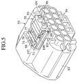
- FIG. 5 is a perspective view showing that the lock-confirming slider 55 is arranged at the male connector 53
- FIG. 6 is a perspective view showing the lock-confirming slider 55.
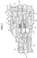
- FIGs. 7 to 10 are perspective views showing an engagement procedure between the male connector 53 of the electric connector 51 and the female connector 57.
- the present embodiment of the electric connector 51 comprises the male type connector 53, the female type connector 57 with which the male type connector 53 is engaged, and the lock-confirming slider 55 for confirming locked condition in which the engagement condition between the male type connector 53 and the female type connector 55 has been maintained.
- the male type connector 53 comprises a waterproof hood 63, having designated space, is formed to be integrated with the outer periphery of the male connector housing 61 where a terminal receiving chamber 59 shaped as two columns of the upper and lower side sections is formed. A part of the outer peripheral wall 63a of the waterproof hood 63 is made open, and a mounting section 65 on which the slider 55 is mounted is formed. A locking arm 67 is provided at the mounting section 67.
- the locking arm 67 comprises a pair of flexible arm sections 71, 71 which are projected in the same direction as the locking arm 67 from the predetermined opening (locking hole) 69 which is opened at the outer peripheral wall 61a of the male connector housing 61, and a coupling section 73 (referring to FIG. 7) which couples the free end side sections of these arm sections 71, 71.
- the free end side sections of the arm sections 71, 71 are covered by the part of the waterproof hood 63.
- an inclined surface 75 is formed at a pointed end section of the coupling section 73, as shown in FIG. 7, an inclined surface 75 is formed.
- an intermediate coupling section 77 which couples the pair of arm section 71, 71 is provided at the intermediate section of the arm sections 71, 71.
- An opposite fitting section 79 is formed across the pair of arm sections 71, 71 between the intermediate coupling section 77 and the coupling section 73.
- a section between the coupling section 73 and the opposite fitting section 79 is the locking hole 69.
- a locking crow 109 described later of the slider 55 comes into contact to be slid and fits with the opposite fitting section 79.
- the slider 55 is mounted on the mounting section 65 in the temporal locking condition in which a lock-detecting arm 95 of the slider 55 is inserted into the section between the pair of arm sections 71, 71 so that the lock-detecting arm 95 comes into contact to be fitted with the coupling section 73, and the male type connector 53 is engaged with the female connector 57.
- an engaging hood 85 in which the male connector housing 61 is engaged is integrally formed with the female connector housing 83 on which a terminal receiving chamber 81 shaped as two columns of the upper and lower side sections is formed.
- An fitting section 87 into which the locking arm 67 is inserted is formed on the fitted hood 85.
- An fitting projection 89 is projected on the inside of the fitting section 87.
- An inclined surface 91 is formed on the fitting projection 89.
- the fitting projection 89 comes into contact with the upper section of the lock-detection arm 95 which comes into contact to be engaged with the coupling section 73 so that the fitting projection 89 pushes the lock-detection arm 95 out of the locking hole 69, with the result that it can be released the fitting condition between the lock-detection arm 95 and the coupling section 73.
- the slider 55 comprises a slider body 93, and the lock-detection arm 95 projected from the slider body 93.
- L-shaped rail sections 99, 99 are integrally formed with both lower sections of the arch-shaped base section 97 respectively in the slider body 93. As shown in FIG. 5, these rail sections 99, 99 are movably fitted into the guide groove 101 provided at the outer peripheral wall 61a of the male connector housing 61 respectively.
- One end of the lock-detection arm 95 is integrally supported with roughly center section of the rail sections 99, 99.
- a column section 107 with a supporting guide 103 and a stopper 105 is formed at the pointed end section of the lock-detection-arm 95.
- a locking crow 109 is projected at the section of the lock-detection arm 95 side, which is the inside section of the base section 97 in the slider 55.
- the locking crow 109 comes into contact to be slid with the upper part of the opposite fitting section 79, and fits with the opposite fitting section 79 after terminating of movement toward the real locking position.
- the condition of engagement of the locking crow 109 with the opposite fitting section 79 can easily be confirmed in such a way that the locking crow 109 can climb over the opposite fitting section 79 so that the moderation-feeling is improved. Further, the condition in which the locking crow 109 has climbed over the opposite fitting section also can be confirmed visually.
- the slider 55 is mounted on the mounting section 65 of the male connector housing 61 ahead of time.
- the stopper 105 at the pointed end of the lock-detection arm 95 comes into contact with the coupling section 73 so that the slider 55 is mounted on the male connector housing 61 at the temporal locking position.
- the male connector housing 61 is engaged with the engaging hood 85 of the female type connector 57
- the engaging hood 85 is engaged with the waterproof hood 63.
- reference numeral 111 shows a member for implementing a halfway-insertion detection of the male terminal
- reference numeral 113 shows a seal member for sealing between the internal wall of the engaging hood 85 and the outer periphery of the male connector housing 61.
- the locking arm 67 can climb over the fitting projection 89 with the locking arm 67 warped, so that it can be obtained the complete engagement condition with the fitting projection 89 inserted into the inside of the locking hole 69, and the fitting projection 89 comes into contact with the lock-detection arm 95, before the engaging projection 89 pushes the lock-detection arm 95 out of the locking hole 69, with the result that the fitting condition of the lock-detection arm 95 with the coupling section 73 is released. For this reason, the slider 55 becomes possible to move from the temporal locking position to the real locking position, when both connector housings 61, 83 are of the complete engagement condition.
- the locking crow 109 climbs over the opposite fitting section 79 so that the locking crow engages with the opposite fitting section 79.
- the lock-detection arm 95 is positioned at the side of the pointed end section of the coupling section 73.
- the fitting projection 89 fits with the inside of the locking hole 69 of the locking arm 67, with the result that the lock-detection arm 95 is positioned at the lower section of the locking arm 67, namely at the lower section of the coupling section 73. For this reason, the locked condition between the male type connector 53 and the female type connector 57 is certainly maintained.
- the locking crow 109 comes into cotact to be slid with the opposite fitting section 79 of the locking arm 67, and when the movement of the slider 55 toward the real locking position is terminated, the locking crow 109 engages with the opposite fitting section 79 all of which is capable of being easily confirmed by the operator making the slider 55 move.
- the opposite fitting section 79 is provided at the locking arm 67, it is not necessary to form the opposite fitting section 79 by the elastic body.
Landscapes
- Details Of Connecting Devices For Male And Female Coupling (AREA)
Abstract
Description
- The present invention relates to an electric connector in which a locking arm and a corresponding fitting section thereto are provided at a female connector housing and a male connector housing respectively, and an engagement of the locking arm with the fitting section would make locked condition between the female connector housing and the male connector housing.
- FIGs. 1 to 3 show an electric connector 1 described in the Japanese Patent Application Laid-Open No. 3-285280. The electric connector 1 which is formed as a waterproof connecter comprises a
male type connector 3, afemale type connector 5, and a lock-confirmingslider 31. Awaterproof hood 13 which surrounds ahood 11 of a female connector housing of thefemale type connector 5 is provided in front of an outer peripheral portion of amale connector housing 7 of themale type connector 3. - A
notch 15 is provided at an upper portion of an outer peripheral wall of thewaterproof hood 13, and alocking arm 17 is provided through asupport 19, fronting onto thenotch 15. - The lock-confirming
slider 31 consists of aslider body 37 and a lock-confirmingarm 39. The lock-confirmingarm 39 is slightly inclined upward, and astopper 41 is projected on the undersurface of a free end portion thereof, and a supportingguide 43 is projected in front thereof. - When the
male connector housing 7 is engaged with thefemale connector housing 9, afitting projection 23 of thelocking arm 17 climbs over (referring to FIG. 2) a prohibiting-return member 35 formed on thehood 11 of thefemale connector housing 9, before thelocking arm 17 is warped upward. When advancing the further engagement, thelocking arm 17 returns elastically downward, before the locking arm is locked due to the engagement between thelocking projection 23 and the prohibiting-return member 35. The lock-confirmingarm 39 is warped upward because thestopper 41 and the supportingguide 43 are engaged with thelocking projection 23. When the engagement therebetween is released, since the obstacle of thestopper 41 is eased, the lock-confirmingarm 39 advances through the passage 27 (referring to FIG. 3) with the result that the lock-confirmingslider 31 arrives at the lock-confirming position. - In this electric connector, the lock-confirming
slider 31 first operates when the engagement and the locking between the female connector housing 9 and themale connector housing 7 are completely implemented, before the engagement of thelocking arm 17 with the lock-confirmingarm 39 is released. Consequently, the confirmation of the complete implementation for the locking is capable of being achieved. - However, in the above-described electric connector, even if the lock-confirming
slider 31 arrives at the lock-confirming section, the lock-confirmingarm 39 only returns the initial position due to the elastic power for itself. The confirmation whether or not the lock-confirmingslider 31 certainly arrives at the lock-confirming position is implemented in such a way that whether or not there feels the touch of the returning of the lock-confirmingarm 39. For this reason, in order to certainly detect the lock-confirmingslider 31 arriving at the lock-confirming position, it is necessary to perform the pulling operation of the lock-confirmingslider 31 whether or not thestopper 41 can be caught by thelocking projection 23, with the result that the operation for confirming locking state is the time-consuming job. - In view of the foregoing, it is an object of the present invention to provide an electric connector in which it can easily be confirmed whether or not a slider is certainly arrived at a lock-confirming position (real locking position), and a lock-confirming operation becomes facile.
- According to one aspect of the present invention, for achieving the above-mentioned object, there is provided an electric connector having a male connector housing, a female connector housing, a flexible locking arm which is provided at the male connector housing, being resiliently deformed during engagement between the male and the female connector housings for permitting relative movement of the male connector housing and the female connector housing, a fitting section which is provided at the female connector housing, for fitting with the locking arm so as to achieve a locked condition when the male connector housing is completely engaged with the female connector housing, a lock-confirming slider universally mounted on the male connector housing which allows it to move to be slid between a temporal locking position and a real locking position, when both connector housings are of the non-complete engagement condition, the slider comes into contact to be engaged with the locking arm so that movement from the temporal locking position to the real locking position is prevented, while when both connector housings are of the complete engagement condition, movement from the temporal locking position to the real locking position is permitted, and for preventing a resilient deformation of the locking arm fitted with the fitting section at a real locking position, a locking crow provided at the slider for confirming real locking, and an opposite fitting section with which the locking crow comes into contact to be slid, when the slider moves from the temporal locking position to the real locking position, and the opposite fitting section fits with the locking crow at the real locking position for being to be confirmed a termination of movement toward the real locking position for the slider.
- As stated above, in this electric connector, after engagement of the male connector housing with the female connector housing, when the lock-confirming slider is moved from the temporal locking position to the real locking position, the locking crow comes into cotact to be slid with the opposite fitting section of the locking arm, and when movement of the slider toward the real locking position is terminated, the locking crow fits with the opposite fitting section. For this reason, the termination of movement for the real locking position of the slider can easily be confirmed with the result that the lock-confirmation operation becomes easy.
- According to the another aspect of the present invention, there is provided an electric connector having slider comprising a slider body, and a flexible lock-detection arm which is projected from the slider body, for coming into contact to be fitted with the locking arm at the temporal locking position, and the time when the locking arm fits with the fitting section, the coming-into-contact to be fitted condition with regard to the locking arm is released due to contacting with the fitting section, when the slider is moved at the real locking position, the lock-detection arm prevents the locking arm from resilient deformation.
- As stated above, when the male connector housing engages with the female connector housing, the locking arm fits with the fitting section and the lock-detection arm fits with the fitting section, so that the coming-into-contact to be fitted condition between the locking arm and the lock-detection arm is released. At this condition, when it makes the slider move from the temporal locking position to the real locking position, the locking crow comes into conact to be slid with the opposite fitting section during this movement, after this sliding contact, on account of fitting of the locking crow with the opposite fitting section, the termination of movement of the slider toward the real locking position can easily be confirmed.
- Further, the locking crow is formed on said slider body, and the opposite fitting section is formed on the outer peripheral wall of the locking arm so that the fitting condition of the locking crow with the opposite fitting section is capable of being confirmed.
- As stated above, after the male connector housing engaging with the female connector housing, when it makes the slider move from the temporal locking position to the real locking position, the locking crow comes into contact to be slid with the opposite fitting section during this movement, on account of fitting between the locking crow and the opposite fitting section, the termination of movement of the slider toward the real locking position can easily be confirmed.
- Furthermore, the locking arm consists of a pair of flexible arm sections which are projected in the same direction thereof from outer peripheral wall of the male connector housing with designated space, and a coupling section for coupling free-end side sections of the arm sections together, whereby the lock-detection arm of the slider is inserted into the space between the arm sections, so that the pointed end section of the lock-detection arm comes into contact to be fitted with said coupling section, with the result that the locking arm is prevented from movement toward the real locking position.
- As stated above, the lock-confirming slider is prevented from movement toward the real locking position because the pointed end section of the lock-detection arm comes into contact to be fitted with the coupling section, and then since the male connector housing is completely engaged with the female connector housing so that it makes both connector housings perform to be locked condition, the fitting section comes into contact to be fitted with the lock-detection arm, thereby the coming-into-contact to be fitted condition between the pointed end section of the lock-detection arm and the coupling section is released, with the result that the lock-confirming slider is permitted to move toward the real locking position. For this reason, the slider does not move from the temporal locking position to the real locking position unintentionally, further, since movement toward the real locking position can easily be confirmed, after having been moved toward the real locking position, the locking crow fits with the opposite fitting section, the slider does not move from the temporal locking position to the real locking position unintentionally.
- Moreover, the opposite fitting section can be formed across between the arm sections at the outer side section of the arm section.
- As stated above, the opposite fitting section can be formed across between the arm sections, thereby the passage in which the pointed end section of the lock-detection arm can be passed through is certainly formed, and the pointed end section of the lock-detection arm certainly comes into contact with the coupling section for coupling the arm section. For this reason, the slider does not move from the temporal locking position to the real locking position unintentionally.
- The above and further objects and novel features of the invention will be more fully understood from the following detailed description when the same is read in connection with the accompanying drawings. It should be expressly understood, however, that the drawings are for purpose of illustration only and are not intended as a definition of the limits of the invention.
-
- FIG. 1 is an exploded perspective view showing a conventional electric connector;
- FIG. 2 is a cross sectional view showing a condition causing a slider to move toward the position for confirming locking state in the conventional electric connector;
- FIG. 3 is a cross sectional view showing a condition where the slider has been moved at the lock-confirming position for confirming locked condition in the conventional electric connector; FIG. 4 is an exploded perspective view showing a male type connector and a slider of the electric connector according to the present invention;
- FIG. 5 is a perspective view showing a condition that the slider is mounted on the male type connector of the electric connector according to the present invention;
- FIG. 6 is a perspective view showing the lock-confirming slider;
- FIG. 7 is a cross sectional view showing a condition that the male type connector housing is started to be inserted into engaging hood of the female type connector in the electric connector;
- FIG. 8 is a cross sectional view showing a condition that the male type connector housing is inserted completely into the engaging hood of the female type connector of the electric connector;
- FIG. 9 is a cross sectional view showing a condition during movement of the slider from the temporal locking position to real locking position with the condition that the male type connector housing is inserted completely into the engaging hood of the female connector;
- FIG. 10 is a cross sectional view showing a condition that the male type connector is engaged with the female type connector, before the slider is moved from the temporal locking section to the real locking section;
- A preferred embodiment of the present invention will now be described in detail referring to the accompanying drawings.
- FIG. 4 is an exploded perspective view showing a relation between a
male connector 53 of anelectric connector 51 and a lock-confirmingslider 55, FIG. 5 is a perspective view showing that the lock-confirmingslider 55 is arranged at themale connector 53, and FIG. 6 is a perspective view showing the lock-confirmingslider 55. Further, FIGs. 7 to 10 are perspective views showing an engagement procedure between themale connector 53 of theelectric connector 51 and thefemale connector 57. - As shown in FIG. 7, The present embodiment of the
electric connector 51 comprises themale type connector 53, thefemale type connector 57 with which themale type connector 53 is engaged, and the lock-confirmingslider 55 for confirming locked condition in which the engagement condition between themale type connector 53 and thefemale type connector 55 has been maintained. - As shown in FIGs. 4 and 5, the
male type connector 53 comprises awaterproof hood 63, having designated space, is formed to be integrated with the outer periphery of themale connector housing 61 where aterminal receiving chamber 59 shaped as two columns of the upper and lower side sections is formed. A part of the outerperipheral wall 63a of thewaterproof hood 63 is made open, and amounting section 65 on which theslider 55 is mounted is formed. Alocking arm 67 is provided at themounting section 67. Thelocking arm 67 comprises a pair offlexible arm sections locking arm 67 from the predetermined opening (locking hole) 69 which is opened at the outerperipheral wall 61a of themale connector housing 61, and a coupling section 73 (referring to FIG. 7) which couples the free end side sections of thesearm sections arm sections waterproof hood 63. - At a pointed end section of the
coupling section 73, as shown in FIG. 7, aninclined surface 75 is formed. Further, anintermediate coupling section 77 which couples the pair ofarm section arm sections opposite fitting section 79 is formed across the pair ofarm sections intermediate coupling section 77 and thecoupling section 73. A section between thecoupling section 73 and theopposite fitting section 79 is thelocking hole 69. Alocking crow 109 described later of theslider 55 comes into contact to be slid and fits with theopposite fitting section 79. - The
slider 55 is mounted on themounting section 65 in the temporal locking condition in which a lock-detectingarm 95 of theslider 55 is inserted into the section between the pair ofarm sections arm 95 comes into contact to be fitted with thecoupling section 73, and themale type connector 53 is engaged with thefemale connector 57. - As shown in FIG. 7, an
engaging hood 85 in which themale connector housing 61 is engaged is integrally formed with the female connector housing 83 on which aterminal receiving chamber 81 shaped as two columns of the upper and lower side sections is formed. Anfitting section 87 into which thelocking arm 67 is inserted is formed on the fittedhood 85. Anfitting projection 89 is projected on the inside of thefitting section 87. Aninclined surface 91 is formed on thefitting projection 89. - As shown in FIG. 7, when the
male type connector 53 engages with thefemale connector 57, aninclined plane 75 of the lockingarm 67 moves to be slid in theinclind surface 91. The lockingarm 67 is resiliently deformed toward themale connector housing 61 so that a relative movement between bothconnector housings male type connector 53 is completely engaged with thefemale type connector 57, thecoupling section 73 and thefitting projection 89 are so fitted that thecoupling section 73 can climb over thefitting projection 89, result in locked condition. At this time, as shown in FIG. 8, thefitting projection 89 comes into contact with the upper section of the lock-detection arm 95 which comes into contact to be engaged with thecoupling section 73 so that thefitting projection 89 pushes the lock-detection arm 95 out of the lockinghole 69, with the result that it can be released the fitting condition between the lock-detection arm 95 and thecoupling section 73. - As shown in FIG. 6, the
slider 55 comprises aslider body 93, and the lock-detection arm 95 projected from theslider body 93. L-shapedrail sections base section 97 respectively in theslider body 93. As shown in FIG. 5, theserail sections guide groove 101 provided at the outerperipheral wall 61a of themale connector housing 61 respectively. - One end of the lock-
detection arm 95 is integrally supported with roughly center section of therail sections column section 107 with a supportingguide 103 and astopper 105 is formed at the pointed end section of the lock-detection-arm 95. - As shown in FIG. 7, in the condition previous to the complete engagement of both
connector housings connector housing 61, the lock-detection arm is inserted into the section between the pair ofarm sections stopper 105 comes into contact to be engaged with thecoupling section 73, and movement toward the real locking position of theslider 55 is prevented. - A locking
crow 109 is projected at the section of the lock-detection arm 95 side, which is the inside section of thebase section 97 in theslider 55. When theslider 55 moves toward the real locking position, the lockingcrow 109 comes into contact to be slid with the upper part of the oppositefitting section 79, and fits with the oppositefitting section 79 after terminating of movement toward the real locking position. At this case, the condition of engagement of the lockingcrow 109 with the oppositefitting section 79 can easily be confirmed in such a way that the lockingcrow 109 can climb over the oppositefitting section 79 so that the moderation-feeling is improved. Further, the condition in which the lockingcrow 109 has climbed over the opposite fitting section also can be confirmed visually. - Next, by using FIGs. 7 to 10, the fitting procedure and lock-confirming operation between the
male connector 53 and thefemale connector 57 will be described. - As shown in FIG. 7, the
slider 55 is mounted on the mountingsection 65 of themale connector housing 61 ahead of time. At this case, thestopper 105 at the pointed end of the lock-detection arm 95 comes into contact with thecoupling section 73 so that theslider 55 is mounted on themale connector housing 61 at the temporal locking position. At this condition, themale connector housing 61 is engaged with the engaginghood 85 of thefemale type connector 57, and the engaginghood 85 is engaged with thewaterproof hood 63. In FIGs. 7 to 10,reference numeral 111 shows a member for implementing a halfway-insertion detection of the male terminal, and reference numeral 113 shows a seal member for sealing between the internal wall of the engaginghood 85 and the outer periphery of themale connector housing 61. - When the
male connector housing 61 is inserted into the engaginghood 85 of thefemale type connector 57, as shown in FIG. 7, the pointed end section of the lockingarm 67 comes into contact with thefitting projection 89 so that theinclined face 75 slides on theinclined surface 91. When it makes themale connector housing 61 further insert into the engaginghood 85, as shown in FIG. 8, the lockingarm 67 can climb over thefitting projection 89 with the lockingarm 67 warped, so that it can be obtained the complete engagement condition with thefitting projection 89 inserted into the inside of the lockinghole 69, and thefitting projection 89 comes into contact with the lock-detection arm 95, before the engagingprojection 89 pushes the lock-detection arm 95 out of the lockinghole 69, with the result that the fitting condition of the lock-detection arm 95 with thecoupling section 73 is released. For this reason, theslider 55 becomes possible to move from the temporal locking position to the real locking position, when bothconnector housings - From this condition, As shown in FIG. 9, when it makes the
slider 55 mounted on the temporal locking position move toward thefemale connector housing 83, the lock-detection arm 95 passes through between thecoupling section 73 and the engaginghood 85, and the lockingcrow 109 comes into contact to be slid with the oppositefitting section 79. The lockingcrow 109 comes into contact to be slid with the oppositefitting section 79 so that the locking arm is slightly warped. Due to the amount of the warp, the engagement of thefitting projection 89 with thecoupling projection 73 can not be released. Further, when it makes theslider 55 move toward thefemale connector housing 83, as shown in FIG. 10, the lockingcrow 109 climbs over the oppositefitting section 79 so that the locking crow engages with the oppositefitting section 79. At the same time, the lock-detection arm 95 is positioned at the side of the pointed end section of thecoupling section 73. - When it makes the
slider 55 move from the temporal locking position to the real locking position, since the lockingcrow 109 comes into contact to be slid with the oppositefitting section 79, before the lockingcrow 109 climbs over the oppositefitting section 79, it is capable of being confirmed that theslider 55 has certainly moved at the real locking position due to improvement of the moderation-feeling. Further, it is capable of being confirmed that theslider 55 has certainly moved at the real locked position by confirming visually of inserting position for theslider 55. - At the condition that the
slider 55 has completely moved at the real locking position, as shown in FIG. 10, thefitting projection 89 fits with the inside of the lockinghole 69 of the lockingarm 67, with the result that the lock-detection arm 95 is positioned at the lower section of the lockingarm 67, namely at the lower section of thecoupling section 73. For this reason, the locked condition between themale type connector 53 and thefemale type connector 57 is certainly maintained. - As stated above, according to the embodiment, when the
slider 55 is moved from the temporal locking position to the real locking position, the lockingcrow 109 comes into cotact to be slid with the oppositefitting section 79 of the lockingarm 67, and when the movement of theslider 55 toward the real locking position is terminated, the lockingcrow 109 engages with the oppositefitting section 79 all of which is capable of being easily confirmed by the operator making theslider 55 move. Namely, when the slide-contact condition for the oppositefitting section 79 of the lockingcrow 109 is terminated, since the sliding resistance at movement of theslider 55 is decreased suddenly, the moderation-feeling is improved, with the result that it is capable of being easily confirmed that the slide-contact of the lockingcrow 109 to the oppositefitting section 79 is terminated. - Further, at the condition that the
slider 55 has moved at the real locking position, since the lockingcrow 109 fits with the fitted position, theslider 55 does not move to the temporal locking position with unpreparedness. - Moreover, according to the embodiment, since the opposite
fitting section 79 is provided at the lockingarm 67, it is not necessary to form the oppositefitting section 79 by the elastic body. - While preferred embodiments of the present invention have been described using specific terms, such description is for illustrative purpose only, and it is to be understood that changes and variations may be made without departing from the spirit or scope of the following claims.
Claims (5)
- An electric connector comprising:a male connector housing;a female connector housing;a flexible locking arm which is provided at said male connector housing, being resiliently deformed during engagement between said male connector housing and said female connector housing for permitting relative movement of said male connector housing and said female connector housing;an fitting section which is provided at said female connector housing, for fitting with said locking arm so as to achieve a locked condition when said male connector housing is completely engaged with said female connector housing;a slider for confirming locked condition universally mounted on said male connector housing which allows it to move to be slid between a temporal locking position and a real locking position, when both connector housings are of the non-complete engagement condition, said slider comes into contact to be engaged with said locking arm so that movement from said temporal locking position to said real locking position is prevented, while when both connector housings are of the complete engagement condition, movement from said temporal locking position to said real locking position is permitted, and for preventing from a resilient deformation of said locking arm fitted with fitting section at a real locking position;a locking crow provided at said slider for confirming real locking; andan opposite fitting section to be fitted with which said locking crow comes into contact to be slid, when said slider moves from said temporal locking position to said real locking position, and said opposite fitting section fits with said locking crow at said real locking position for being to be confirmed a termination of the movement toward said real locking position for said slider.
- An electric connector as claimed in claim 1, wherein said slider comprises a slider body, and a flexible lock-detection arm which is projected from said slider body, for coming into contact to be fitted with said locking arm at said temporal locking position, and the time when said locking arm fits with said fitting section, the coming-into-contact to be fitted condition with regard to said locking arm is released due to contacting with said fitting section, when said slider is moved at said real locking position, said lock-detection arm prevents said locking arm from resilient deformation.
- An electric connector as claimed in claim 2, wherein said locking crow is formed on said slider body, and said opposite fitting section is formed on the outer peripheral wall of said locking arm so that the fitting condition of said locking crow and said opposite fitting section is capable of being confirmed.
- An electric connector as claimed in claim 2 or 3, wherein said locking arm comprises a pair of flexible arm sections which are projected in the same direction thereof from outer peripheral wall of said male connector housing with designated space, and a coupling section for coupling free-end side sections of said arm sections together, whereby said lock-detection arm of said slider is inserted into said space between said arm sections, so that the pointed end section of said lock-detection arm comes into contact to be fitted with said coupling section, with the result that said locking arm is prevented from movement toward said real locking position.
- An electric connector as claimed in claim 4, wherein said opposite fitting section is formed across between said arm sections at the outer side section of said arm section.
Applications Claiming Priority (3)
| Application Number | Priority Date | Filing Date | Title |
|---|---|---|---|
| JP243195/95 | 1995-09-21 | ||
| JP24319595A JP3228854B2 (en) | 1995-09-21 | 1995-09-21 | Electrical connector |
| JP24319595 | 1995-09-21 |
Publications (3)
| Publication Number | Publication Date |
|---|---|
| EP0788193A2 true EP0788193A2 (en) | 1997-08-06 |
| EP0788193A3 EP0788193A3 (en) | 1997-10-15 |
| EP0788193B1 EP0788193B1 (en) | 2000-12-13 |
Family
ID=17100253
Family Applications (1)
| Application Number | Title | Priority Date | Filing Date |
|---|---|---|---|
| EP96115138A Expired - Lifetime EP0788193B1 (en) | 1995-09-21 | 1996-09-20 | Electric connector |
Country Status (4)
| Country | Link |
|---|---|
| US (1) | US5879180A (en) |
| EP (1) | EP0788193B1 (en) |
| JP (1) | JP3228854B2 (en) |
| DE (1) | DE69611222T2 (en) |
Cited By (10)
| Publication number | Priority date | Publication date | Assignee | Title |
|---|---|---|---|---|
| EP0977322A3 (en) * | 1998-07-30 | 2002-09-04 | Tyco Electronics Logistics AG | Connector module |
| EP1225659A3 (en) * | 2001-01-23 | 2003-01-02 | F.C.I. - Framatome Connectors International | Electrical connecting unit |
| EP1176676A3 (en) * | 2000-07-24 | 2003-08-13 | Yazaki Corporation | Connector fitting structure |
| WO2006053717A1 (en) | 2004-11-16 | 2006-05-26 | Fci | Plug connector arrangement with secondary locking |
| EP1763114A1 (en) * | 2005-09-13 | 2007-03-14 | Sumitomo Wiring Systems, Ltd. | An electrical connector |
| WO2008084339A1 (en) * | 2007-01-08 | 2008-07-17 | Fci | Electrical connector assembly with improved locking means |
| EP1513225A3 (en) * | 2003-09-06 | 2009-11-04 | Hirschmann Automotive GmbH | Locking element for electric connector assembly |
| EP2772993A1 (en) * | 2013-02-28 | 2014-09-03 | Yazaki North America, Inc. | Connector assembly with connector position assurance stabilizer |
| EP3024097A1 (en) * | 2014-11-19 | 2016-05-25 | Sumitomo Wiring Systems, Ltd. | Connector, connector assembly and assembling method therefor |
| CN110710061A (en) * | 2017-06-06 | 2020-01-17 | 日本端子株式会社 | connector structure |
Families Citing this family (22)
| Publication number | Priority date | Publication date | Assignee | Title |
|---|---|---|---|---|
| US6261115B1 (en) * | 1999-06-11 | 2001-07-17 | Tyco Electronics Logistics Ag | Connector module |
| US6045388A (en) * | 1998-09-02 | 2000-04-04 | Molex Incorporated | Electrical connector position assurance system |
| US6174190B1 (en) * | 1999-10-26 | 2001-01-16 | Keith Frank Tharp | Connector having a slide rail latch release |
| US6261116B1 (en) * | 1999-11-22 | 2001-07-17 | Yazaki North America, Inc. | Connector position assurance element with lock protection feature |
| US6273741B1 (en) | 2000-01-14 | 2001-08-14 | Daimlerchrysler Corporation | Locking connector for antenna cable |
| JP3607884B2 (en) * | 2001-07-09 | 2005-01-05 | 日本圧着端子製造株式会社 | Electrical connector assembly and connector used therefor |
| JP2003142209A (en) * | 2001-11-07 | 2003-05-16 | Sumitomo Wiring Syst Ltd | Connector |
| JP3997858B2 (en) * | 2002-07-24 | 2007-10-24 | 住友電装株式会社 | Mating detection connector |
| JP2004319374A (en) * | 2003-04-18 | 2004-11-11 | Japan Aviation Electronics Industry Ltd | connector |
| JP2007200767A (en) * | 2006-01-27 | 2007-08-09 | Yazaki Corp | Connector |
| US7354291B2 (en) * | 2006-03-01 | 2008-04-08 | Panduit Corp. | Plug locking assembly |
| JP5751196B2 (en) * | 2012-03-09 | 2015-07-22 | 住友電装株式会社 | connector |
| US8920187B2 (en) * | 2012-03-09 | 2014-12-30 | Sumitomo Wiring Systems, Ltd. | Connector and connector assembly |
| US8926355B2 (en) * | 2012-06-29 | 2015-01-06 | Lear Corporation | Connector position assurance device for a connector assembly |
| JP6213592B2 (en) * | 2016-02-25 | 2017-10-18 | 第一精工株式会社 | connector |
| US9935389B1 (en) * | 2017-02-23 | 2018-04-03 | Sumitomo Wiring Systems, Ltd. | Inline connector housing assemblies with removable TPA |
| CN109616829B (en) * | 2017-10-04 | 2020-04-24 | 矢崎总业株式会社 | Connector with a locking member |
| US10181679B1 (en) * | 2017-10-20 | 2019-01-15 | Lear Corporation | Electrical connector with terminal position assurance |
| US10218124B1 (en) * | 2017-10-20 | 2019-02-26 | Lear Corporation | Electrical connector with terminal position assurance |
| US10355414B1 (en) | 2018-02-08 | 2019-07-16 | Delphi Technologies, Llc | Connector with a connector position assurance device |
| JP6865725B2 (en) * | 2018-10-31 | 2021-04-28 | 矢崎総業株式会社 | connector |
| US11387604B2 (en) | 2020-10-14 | 2022-07-12 | Aptiv Technologies Limited | Wave connector position assurance lock with dual overlap connector lock |
Family Cites Families (11)
| Publication number | Priority date | Publication date | Assignee | Title |
|---|---|---|---|---|
| JPS59148287A (en) * | 1983-02-14 | 1984-08-24 | 日本電気株式会社 | Connector |
| US4634204A (en) * | 1985-12-24 | 1987-01-06 | General Motors Corporation | Electrical connector with connector position assurance/assist device |
| US4708413A (en) * | 1986-03-21 | 1987-11-24 | General Motors Corporation | Electrical connector with position assurance and assist |
| US4946395A (en) * | 1989-07-17 | 1990-08-07 | General Motors Corporation | Electrical connector with connector position assurance device |
| JP2537302B2 (en) * | 1990-03-01 | 1996-09-25 | 矢崎総業株式会社 | Lock check device for electrical connector |
| US5120255A (en) * | 1990-03-01 | 1992-06-09 | Yazaki Corporation | Complete locking confirming device for confirming the complete locking of an electric connector |
| JP2563323Y2 (en) * | 1990-10-22 | 1998-02-18 | 矢崎総業株式会社 | connector |
| JPH05135823A (en) * | 1991-11-11 | 1993-06-01 | Yazaki Corp | Locking device of connector |
| JP2596169Y2 (en) * | 1992-06-22 | 1999-06-07 | 矢崎総業株式会社 | Waterproof connector |
| EP0655807A3 (en) * | 1993-11-30 | 1995-12-13 | Whitaker Corp | Device for ensuring the position of the connector. |
| JP2921645B2 (en) * | 1994-07-12 | 1999-07-19 | 矢崎総業株式会社 | Connector mating detection structure |
-
1995
- 1995-09-21 JP JP24319595A patent/JP3228854B2/en not_active Expired - Fee Related
-
1996
- 1996-09-20 US US08/717,274 patent/US5879180A/en not_active Expired - Fee Related
- 1996-09-20 DE DE69611222T patent/DE69611222T2/en not_active Expired - Lifetime
- 1996-09-20 EP EP96115138A patent/EP0788193B1/en not_active Expired - Lifetime
Cited By (14)
| Publication number | Priority date | Publication date | Assignee | Title |
|---|---|---|---|---|
| EP0977322A3 (en) * | 1998-07-30 | 2002-09-04 | Tyco Electronics Logistics AG | Connector module |
| EP1176676A3 (en) * | 2000-07-24 | 2003-08-13 | Yazaki Corporation | Connector fitting structure |
| EP1225659A3 (en) * | 2001-01-23 | 2003-01-02 | F.C.I. - Framatome Connectors International | Electrical connecting unit |
| EP1513225A3 (en) * | 2003-09-06 | 2009-11-04 | Hirschmann Automotive GmbH | Locking element for electric connector assembly |
| WO2006053717A1 (en) | 2004-11-16 | 2006-05-26 | Fci | Plug connector arrangement with secondary locking |
| CN101076925B (en) * | 2004-11-16 | 2010-05-05 | Fci公司 | Plug connector structure with secondary locking device |
| US7766685B2 (en) | 2004-11-16 | 2010-08-03 | Fci | Plug connector arrangement with secondary locking |
| EP1763114A1 (en) * | 2005-09-13 | 2007-03-14 | Sumitomo Wiring Systems, Ltd. | An electrical connector |
| WO2008084339A1 (en) * | 2007-01-08 | 2008-07-17 | Fci | Electrical connector assembly with improved locking means |
| EP2772993A1 (en) * | 2013-02-28 | 2014-09-03 | Yazaki North America, Inc. | Connector assembly with connector position assurance stabilizer |
| US9160095B2 (en) | 2013-02-28 | 2015-10-13 | Yazaki North America, Inc. | Connector assembly with connector position assurance stabilizer |
| EP3024097A1 (en) * | 2014-11-19 | 2016-05-25 | Sumitomo Wiring Systems, Ltd. | Connector, connector assembly and assembling method therefor |
| CN110710061A (en) * | 2017-06-06 | 2020-01-17 | 日本端子株式会社 | connector structure |
| CN110710061B (en) * | 2017-06-06 | 2021-03-30 | 日本端子株式会社 | Connector structure |
Also Published As
| Publication number | Publication date |
|---|---|
| JPH0992398A (en) | 1997-04-04 |
| EP0788193B1 (en) | 2000-12-13 |
| DE69611222T2 (en) | 2001-05-17 |
| US5879180A (en) | 1999-03-09 |
| DE69611222D1 (en) | 2001-01-18 |
| EP0788193A3 (en) | 1997-10-15 |
| JP3228854B2 (en) | 2001-11-12 |
Similar Documents
| Publication | Publication Date | Title |
|---|---|---|
| EP0788193B1 (en) | Electric connector | |
| US6840789B2 (en) | Connector and a method of assembling it | |
| US5051100A (en) | Electrical connector | |
| US5637009A (en) | Connector equipped with engagement detecting member | |
| JP4071009B2 (en) | Waterproof electrical connector assembly | |
| US5785546A (en) | Connector locking structure | |
| US20080233789A1 (en) | Lock structure of connector | |
| US5203715A (en) | Connector | |
| US4940430A (en) | Electrical connector with openable cover | |
| CA2353425C (en) | Connector fitting structure | |
| US5088938A (en) | Terminal locking block for electrical connectors | |
| JPH0612632Y2 (en) | Connector with slide cover | |
| JP2001244025A (en) | Connector mating structure | |
| JP2600796Y2 (en) | Arm connection type connector | |
| JPH08306431A (en) | Connector with terminal locking device | |
| US5964602A (en) | Connector fitting structure and method | |
| US6527578B2 (en) | Connector fitting structure | |
| EP1146605B1 (en) | Connector | |
| JPH0690940B2 (en) | Electrical connector with double locking structure for terminal fittings | |
| US5755587A (en) | Connector with engagement confirming mechanism | |
| EP0877447A2 (en) | Connector | |
| EP1058353B1 (en) | Connector | |
| JPH0869842A (en) | connector | |
| JPH1050386A (en) | Connector | |
| US5800202A (en) | Electrical connector assembly with coupling guide structure |
Legal Events
| Date | Code | Title | Description |
|---|---|---|---|
| PUAI | Public reference made under article 153(3) epc to a published international application that has entered the european phase |
Free format text: ORIGINAL CODE: 0009012 |
|
| 17P | Request for examination filed |
Effective date: 19960920 |
|
| AK | Designated contracting states |
Kind code of ref document: A2 Designated state(s): DE ES FR GB IT |
|
| PUAL | Search report despatched |
Free format text: ORIGINAL CODE: 0009013 |
|
| AK | Designated contracting states |
Kind code of ref document: A3 Designated state(s): DE ES FR GB IT |
|
| 17Q | First examination report despatched |
Effective date: 19980114 |
|
| GRAG | Despatch of communication of intention to grant |
Free format text: ORIGINAL CODE: EPIDOS AGRA |
|
| 17Q | First examination report despatched |
Effective date: 19980114 |
|
| GRAG | Despatch of communication of intention to grant |
Free format text: ORIGINAL CODE: EPIDOS AGRA |
|
| GRAH | Despatch of communication of intention to grant a patent |
Free format text: ORIGINAL CODE: EPIDOS IGRA |
|
| GRAH | Despatch of communication of intention to grant a patent |
Free format text: ORIGINAL CODE: EPIDOS IGRA |
|
| GRAA | (expected) grant |
Free format text: ORIGINAL CODE: 0009210 |
|
| AK | Designated contracting states |
Kind code of ref document: B1 Designated state(s): DE ES FR GB IT |
|
| PG25 | Lapsed in a contracting state [announced via postgrant information from national office to epo] |
Ref country code: IT Free format text: LAPSE BECAUSE OF FAILURE TO SUBMIT A TRANSLATION OF THE DESCRIPTION OR TO PAY THE FEE WITHIN THE PRESCRIBED TIME-LIMIT;WARNING: LAPSES OF ITALIAN PATENTS WITH EFFECTIVE DATE BEFORE 2007 MAY HAVE OCCURRED AT ANY TIME BEFORE 2007. THE CORRECT EFFECTIVE DATE MAY BE DIFFERENT FROM THE ONE RECORDED. Effective date: 20001213 Ref country code: FR Free format text: LAPSE BECAUSE OF FAILURE TO SUBMIT A TRANSLATION OF THE DESCRIPTION OR TO PAY THE FEE WITHIN THE PRESCRIBED TIME-LIMIT Effective date: 20001213 Ref country code: ES Free format text: THE PATENT HAS BEEN ANNULLED BY A DECISION OF A NATIONAL AUTHORITY Effective date: 20001213 |
|
| REF | Corresponds to: |
Ref document number: 69611222 Country of ref document: DE Date of ref document: 20010118 |
|
| EN | Fr: translation not filed | ||
| PG25 | Lapsed in a contracting state [announced via postgrant information from national office to epo] |
Ref country code: GB Free format text: LAPSE BECAUSE OF NON-PAYMENT OF DUE FEES Effective date: 20010920 |
|
| PLBE | No opposition filed within time limit |
Free format text: ORIGINAL CODE: 0009261 |
|
| STAA | Information on the status of an ep patent application or granted ep patent |
Free format text: STATUS: NO OPPOSITION FILED WITHIN TIME LIMIT |
|
| 26N | No opposition filed | ||
| REG | Reference to a national code |
Ref country code: GB Ref legal event code: IF02 |
|
| GBPC | Gb: european patent ceased through non-payment of renewal fee |
Effective date: 20010920 |
|
| PGFP | Annual fee paid to national office [announced via postgrant information from national office to epo] |
Ref country code: DE Payment date: 20090917 Year of fee payment: 14 |
|
| REG | Reference to a national code |
Ref country code: DE Ref legal event code: R119 Ref document number: 69611222 Country of ref document: DE Effective date: 20110401 |
|
| PG25 | Lapsed in a contracting state [announced via postgrant information from national office to epo] |
Ref country code: DE Free format text: LAPSE BECAUSE OF NON-PAYMENT OF DUE FEES Effective date: 20110401 |