EP0788100B1 - Automatic cassette changer - Google Patents
Automatic cassette changer Download PDFInfo
- Publication number
- EP0788100B1 EP0788100B1 EP97103693A EP97103693A EP0788100B1 EP 0788100 B1 EP0788100 B1 EP 0788100B1 EP 97103693 A EP97103693 A EP 97103693A EP 97103693 A EP97103693 A EP 97103693A EP 0788100 B1 EP0788100 B1 EP 0788100B1
- Authority
- EP
- European Patent Office
- Prior art keywords
- cassette
- recording
- hand block
- automatic
- cassettes
- Prior art date
- Legal status (The legal status is an assumption and is not a legal conclusion. Google has not performed a legal analysis and makes no representation as to the accuracy of the status listed.)
- Expired - Lifetime
Links
Images


Classifications
-
- G—PHYSICS
- G11—INFORMATION STORAGE
- G11B—INFORMATION STORAGE BASED ON RELATIVE MOVEMENT BETWEEN RECORD CARRIER AND TRANSDUCER
- G11B15/00—Driving, starting or stopping record carriers of filamentary or web form; Driving both such record carriers and heads; Guiding such record carriers or containers therefor; Control thereof; Control of operating function
- G11B15/675—Guiding containers, e.g. loading, ejecting cassettes
- G11B15/68—Automatic cassette changing arrangements; automatic tape changing arrangements
- G11B15/682—Automatic cassette changing arrangements; automatic tape changing arrangements with fixed magazines having fixed cassette storage cells, e.g. in racks
- G11B15/6835—Automatic cassette changing arrangements; automatic tape changing arrangements with fixed magazines having fixed cassette storage cells, e.g. in racks the cassettes being transferred to a fixed recorder or player using a moving carriage
-
- G—PHYSICS
- G11—INFORMATION STORAGE
- G11B—INFORMATION STORAGE BASED ON RELATIVE MOVEMENT BETWEEN RECORD CARRIER AND TRANSDUCER
- G11B15/00—Driving, starting or stopping record carriers of filamentary or web form; Driving both such record carriers and heads; Guiding such record carriers or containers therefor; Control thereof; Control of operating function
- G11B15/675—Guiding containers, e.g. loading, ejecting cassettes
- G11B15/68—Automatic cassette changing arrangements; automatic tape changing arrangements
- G11B15/682—Automatic cassette changing arrangements; automatic tape changing arrangements with fixed magazines having fixed cassette storage cells, e.g. in racks
- G11B15/6825—Details of magazines, e.g. removable, adapted for cassettes of different sizes
-
- G—PHYSICS
- G11—INFORMATION STORAGE
- G11B—INFORMATION STORAGE BASED ON RELATIVE MOVEMENT BETWEEN RECORD CARRIER AND TRANSDUCER
- G11B17/00—Guiding record carriers not specifically of filamentary or web form, or of supports therefor
- G11B17/22—Guiding record carriers not specifically of filamentary or web form, or of supports therefor from random access magazine of disc records
- G11B17/225—Guiding record carriers not specifically of filamentary or web form, or of supports therefor from random access magazine of disc records wherein the disks are transferred from a fixed magazine to a fixed playing unit using a moving carriage
-
- G—PHYSICS
- G11—INFORMATION STORAGE
- G11B—INFORMATION STORAGE BASED ON RELATIVE MOVEMENT BETWEEN RECORD CARRIER AND TRANSDUCER
- G11B25/00—Apparatus characterised by the shape of record carrier employed but not specific to the method of recording or reproducing, e.g. dictating apparatus; Combinations of such apparatus
- G11B25/06—Apparatus characterised by the shape of record carrier employed but not specific to the method of recording or reproducing, e.g. dictating apparatus; Combinations of such apparatus using web-form record carriers, e.g. tape
- G11B25/066—Apparatus characterised by the shape of record carrier employed but not specific to the method of recording or reproducing, e.g. dictating apparatus; Combinations of such apparatus using web-form record carriers, e.g. tape adapted for use with containers of different sizes or configurations; adaptor devices therefor
Definitions
- This invention relates to an automatic cassette changer.
- the automatic cassette changer is convenient in that cassettes of the large and small sizes are selectively used in such a manner that a cassette of the small size is used to televise a video signal for a comparatively short period of time such as a commercial, but a cassette of the large size is used to televise a video signal fir a comparative long period of time such as a news or other programs.
- the prior art automatic cassette changer can handle only cassettes wherein the recording format of the tapes therein is common. Consequently, it is quite impossible to properly use a plurality of types of cassettes wherein the tapes therein have different recording formats such as those tapes which have been photographed with different video cameras having different recording formats.
- the automatic cassette changer with a cassette transporting machine includes two drawing in mechanisms including a main cassette drawing in mechanism and an auxiliary cassette drawing in mechanism, by means of which a cassette drawing in operation of a long stroke can be performed compactly.
- the cassette drawing in mechanisms cannot be moved in a direction perpendicular to the inserting or removing direction of a cassette with respect to the transporting machine, and the movement in the perpendicular direction can be achieved only by horizontal movement of the entire transporting machine.
- the entire transporting machine must be moved in the vertical direction and the leftward and rightward horizontal direction, which makes the moving apparatus large-scaled.
- the automatic cassette changer disclosed in Japanese Patent Laid-Open Application No. 3-156382 is further constructed such that the transporting machine includes a pair of upper and lower cassette holding pawls mounted for pivotal motion in the upward and downward directions such that a cassette is held in its thicknesswise direction by and between the cassette holding pawls to effect insertion or removal of the cassette into or from a cassette accommodating rack or the recording and reproducing apparatus.
- the transporting machine is displaced or offset in the vertical direction with respect to the cassette accommodating rack and the recording and reproducing apparatus, then when a cassette is to be inserted from the transporting machine into the cassette accommodating rack or the recording and reproducing apparatus, then an end of the cassette may be abutted with and pinched in the cassette accommodating rack or the recording reproducing apparatus which has a high rigidity, and consequently, the cassette cannot be inserted farther than an intermediate position.
- a cassette which is discharged, for example, from the recording and reproducing apparatus does not always assume a correct posture but assumes, in most cases, an inclined position within a horizontal plane with respect the transporting machine due to the structure of the automatic cassette changer. Further, the relative distances of the transporting machine from the cassette accommodating rack and the recording and reproducing apparatus in the cassette inserting or removing direction are liable to present a considerable dispersion.
- a cassette of one of the various types may not be held stably by and between the cassette holding pawls depending upon the thickness of it.
- the prior art automatic cassette changer can handle only cassettes of the equal thickness, and it is difficult to realize an automatic cassette changer in which a plurality of cassettes having different thicknesses in accordance with recording formats can be used to effect continuous video signal reproduction, recording, edition or the like over a long period of time.
- a further automatic cassette changer has been proposed by the assignee of the present patent application and is disclosed in Japanese Patent Laid-Open Application No. 1-151448 wherein a plurality of types of cassettes having different large and small sizes can be automatically exchanged to effect continuous video signal reproduction, recording, edition or the like over a long period of time.
- the automatic cassette changer is convenient in that cassettes of large and small sizes are selectively used in such a manner that a cassette of the small size is used to televise a video signal for a comparatively short period of time such as a commercial, but a cassette of the large size is used to televise a video signal for a comparative long period of time such as a news or other programs.
- the automatic cassette changer can handle only cassettes wherein the recording format of the tapes therein is common. Consequently, it is quite impossible to properly use a plurality of types of cassettes wherein the tapes therein have different recording formats such as those tapes which have been photographed with different video cameras having different recording formats.
- the automatic cassette changer is constructed such that the transporting machine is moved by itself by a motor provided on the transporting machine itself in a vertical direction along a vertical rack of a body of the automatic cassette changer, and the entire automatic cassette changer can be constructed compactly.
- a pair of left and right travel guides for the transporting machine are each constituted from a fixed rail mounted on the automatic cassette changer body and extending in a direction perpendicular to the cassette inserting or removing direction, and a plurality of guide rollers mounted on the transporting machine and always held in contact in the cassette inserting or removing direction with the fixed rail, and accordingly, it is difficult to restrict the movement or play of the transporting machine in the leftward or rightward direction, that is, in a direction perpendicular to the cassette inserting or removing direction.
- an additional fixed rail extending in parallel to the cassette inserting and removing direction and a plurality of additional guide rollers normally held in contact in a direction perpendicular to the cassette inserting or removing direction with the additional fixed rail must be provided.
- the prior art automatic cassette changer disclosed in Japanese Patent Laid-Open Application No. 243265 further has a drawback that, since any of cassettes of the different large and small sizes is positioned at the center of the transporting machine by means of a cassette guide disposed in the transporting machine, the position at which a cassette, for example, of the small size is transferred to or from the cassette accommodating rack or the recording and reproducing apparatus cannot be selected freely in a direction perpendicular to the cassette inserting and removing direction.
- the automatic cassette changer disclosed in Japanese Patent Laid-Open Application No. 3-156382 is constructed such that it includes two drawing in mechanisms including a main cassette drawing in mechanism and an auxiliary cassette drawing in mechanism, by means of which a cassette drawing in operation of a long stroke can be performed.
- the cassette holding pawls must necessarily have a considerably great length, but if the cassette holding pawls are excessively long, then the depth to which they can insert a cassette into the recording and reproducing apparatus is further restricted. Consequently, there is a problem that it is actually impossible to push in a cassette of the small size to the interior position in the recording and reproducing apparatus so that the front end face of the small size cassette may be positioned in register with the front end face of a cassette of the large size.
- European patent application EP-A-0 288 165 is used for the delimitation of claim 1 and discloses an automatic cassette changer that is extendable by detachably coupling additional units containing cassette storage cases.
- an automatic cassette changer comprising:
- the entire hand block is automatically moved in the thicknesswise direction of the selected cassette in accordance with the vertical position of the selected cassette, thereby exhibiting an automatic centering function. Consequently, such an otherwise possible trouble can be prevented that the selected cassette during inserting or removing operation is contacted with and caught by the selected bin or recording and/or recording apparatus which is high in rigidity.
- the tolerances of the components of the system and the accuracy in assembly of the components as well as the accuracy of the stopping position of the transporting machine with respect to each of the bins of the cassette accommodating rack and the recording and/or reproducing apparatus need not be made very severe, and consequently, reduction of the overall cost of the apparatus can be achieved.
- a special servo circuit or a like circuit for stopping the transporting machine at a precise position with respect to a selected one of the bins of the accommodating rack and the recording and/or reproducing apparatus can be eliminated, and reduction of the overall cost of the apparatus can be achieved.
- the hand block includes a pair of upper and lower cassette holding elements for holding the selected cassette therebetween and an opening and closing mechanism for opening and closing the cassette holding elements while keeping the cassette holding elements in parallel to each other.
- one of the cassette holding elements of the hand block is fixed while the other cassette holding element is mounted for parallel movement with respect to the fixed cassette holding element.
- the pair of cassette holding elements for holding a cassette in its thicknesswise direction are opened or closed while keeping the parallel positions to each other so that a cassette having one of several thicknesses can be held always with stability by and between the cassette holding elements, continuous video signal reproduction, recording or edition over a long period of time can be performed with the automatic cassette changer while using the plurality of types of cassettes for which the recording formats are different from each other. Also, an operation of transporting the selected cassette can be performed with stability, and such an otherwise possible accident can be prevented that the cassette being transported is let off from the hand block.
- An embodiment of the automatic cassette changer comprises a cassette inclination sensor for detecting an inclination of the selected cassette to be held between the cassette holding elements with respect to the hand block.
- an inclination of the cassette with respect to the hand block can be detected by the cassette inclination sensor provided on the hand block of the transporting machine and can be automatically corrected, and also the dispersion of the relative distance between the cassette and the transporting machine can be automatically absorbed by the inclination correcting operation for the cassette.
- the cassette discharge in an unstable posture to an unstable position from the recording and/or reproducing apparatus can be held always with a very high degree of stability without having any inclination with respect to the hand block, and the holding position of the cassette by the cassette holding elements can be assured at an accurate position and the cassette can always be held with certainty by and between the cassette holding elements. Accordingly, when a cassette held by the cassette holding elements is to be removed from a recording and/or reproducing apparatus or the like by means of the hand block, the cassette will not be displaced inadvertently and can be removed always smoothly.
- An embodiment of the automatic cassette changer comprises a feed screw for controlling the opening and closing movement of the cassette holding elements, and a torque limiter for controlling the force by which the selected cassette is to be held between the cassette holding elements.
- the automatic cassette changer since the opening and closing control of the pair of cassette holding elements is performed by the feed screw so that a cassette which has one of different thicknesses can be held uniformly without any trouble by and between the cassette holding elements, the automatic cassette changer can use the plurality of cassettes which have the different thicknesses in accordance with the recording formats of record media of the cassettes. Further, even if the power supply to the automatic cassette changer is interrupted inadvertently during transportation of a cassette or in a like case, otherwise possible letting off of the cassette is prevented.
- the holding force when a cassette is to be held by and between the cassette holding elements can be set to a fixed value by means of the torque limiter whichever thickness the cassette has, the cassette can be held and transported always with stability irrespective of the thickness of the cassette, and there is no disadvantage that the holding force to the cassette is so great due to the difference of the thickness of the cassette as to inadvertently damage the cassette.
- the holding force to the cassette can be set to a fixed value by means of the torque limiter while the opening and closing control of the cassette holding elements is performed by the feed screw, such an accident that, when the cassette is held by and between the cassette holding elements, a nut cooperating with the feed screw bites into the feed screw to lock the feed screw does not take place at all.
- An embodiment of the automatic cassette changer comprises an opening amount controlling means for controlling the opening amount of the cassette holding elements in accordance with information of the thickness of the selected cassette.
- the opening amount of the cassette holding elements is controlled in accordance with information of the thickness of the cassette, and accordingly, the cassette having any thickness can be held very rapidly and transported lightly by the cassette holding elements. Consequently, the time for exchanging cassettes can be reduced remarkably. Further, since the opening amount of the cassette holding elements can be controlled in accordance with a thickness of a cassette which has one of several thicknesses, when the cassette holding elements are to be inserted, for example, above and below a cassette in the accommodating rack to hold the cassette in its thicknesswise direction therebetween, the insertion and holding of the cassette holding elements can be performed within a minimum spacing in the accommodating rack.
- the bins of the accommodating rack can be disposed at a minimum pitch to achieve a high accommodating efficiency of cassettes in a small spacing.
- the opening amount of the cassette holding elements is controlled in accordance with information of the thickness of the cassette by the opening amount controlling means such as an encoder, optimum opening amounts for the cassettes having the several thicknesses can be set very simply, and also modification to or addition of an opening amount can be performed readily.
- An embodiment of the automatic cassette changer comprises a plurality of cassettes in which record medium are individually accommodated.
- the embodiment of the automatic cassette changer comprises a plurality of types of cassettes in which different types of record media for different recording formats are accommodated, and the plurality of recording and/or reproducing apparatus are each provided for selectively recording and/or reproducing a format signal in accordance with a selected one of the recording format signal in accordance with a selected one of the recording formats of the plurality of types of cassettes.
- the automatic cassette changer since the plurality of types of cassettes for which the recording formats are different from each other are accommodated in the bins of the accommodating rack and the plurality of recording and/or reproducing apparatus each for selectively recording and/or reproducing a format signal in accordance with a selected one of the recording formats of the plurality of types of cassettes are accommodated in the automatic cassette changer so that the plurality of types of cassettes for which the recording formats are different from each other can be continuously recorded and/or reproduced successively with the single automatic cassette changer, continuous video signal reproduction, recording or edition over a long period of time can be performed with the single automatic cassette changer while using the plurality of types of cassettes for which the recording formats are different from each other.
- the automatic cassette changer can be constructed as an apparatus for exclusive use for a particular user by employing a plurality of desired types of cassettes for which the recording formats are different from each other and a plurality of recording and/reproducing apparatus for the plurality of types of cassettes as desired by the user.
- the plurality of types of cassettes are accommodated in a plurality of accommodating units in each of which a plurality of cassettes of the same type are accommodated, and the accommodating units and the recording and/orreproducing apparatus are individually exchangeable with another unit or apparatus.
- the automatic cassette changer since the plurality of types of cassettes are accommodated in the plurality of accommodating units in each of which a plurality of cassettes of the same type are accommodated and the accommodating units and the recording and/or reproducing apparatus can be changed as desired, a plurality of types of cassettes which are different from each other or for which the recording formats are different from each other can be selectively used as desired by the user.
- each of the accommodating units has a first type detecting section representative of the type of the accommodating unit and each of the recording and/or reproducing apparatus has a second type detecting section representative of the type of the recording and/or reproducing apparatus while the transporting machine has a type detecting sensor for reading the first or second detecting portion to control operation of the transporting machine.
- the automatic cassette changer since any of the first and second type detecting sections provided for the accommodating units and the recording and/or reproducing apparatus is read by the type detecting sensor provided on the transporting machine to discriminate the type of the accommodating unit or the recording and/or reproducing apparatus and control operation of the transporting machine, the arrangement of the accommodating units and the recording and/or reproducing apparatus can be changed freely as desired by the user, and even if any one of the accommodating units and the recording and/or reproducing apparatus is exchanged for another unit or apparatus, an automatic exchanging operation can still be performed with certainty.
- the hand block is movable in the direction in which the hand block inserts or removes the selected cassette into or from the selected one of the bins and the recording and/or reproducing apparatus and in a direction perpendicular to the cassette inserting or removing direction.
- the hand block for holding a selected one of the cassettes and inserting or removing the selected cassettes into or from a selected one of the bins and the recording and/or reproducing apparatus is provided on the transporting machine and is disposed for movement in the cassette inserting or removing direction and the direction perpendicular to the cassette inserting or removing direction, and the position at which the selected cassette is to be transferred can be freely selected in the direction perpendicular to the cassette inserting or removing direction with respect to the transporting machine while the transporting machine is moved simply in one direction such as in a vertical direction.
- any of the bins and cassette insertion openings of the recording and/or reproducing apparatus can be set freely in the direction perpendicular to the cassette inserting or removing direction, and transfer of the selected cassette to any of them can be performed freely only by means of the hand block without moving the transporting machine in the direction perpendicular to the cassette inserting or removing direction. Consequently, the automatic cassette changer which comprises the plurality of types of cassettes for which the recording formats are different from each other and the plurality of the recording and/or reproducing apparatus for the plurality of types of cassettes can be constructed readily.
- the transporting machine includes a slider disposed for linear movement in the direction perpendicular to the direction in which the hand block inserts or removes the selected cassette into or from the selected one of the bins and the recording and/or reproducing apparatus and a pivotal arm mounted at an end thereof for pivotal motion on the slider and having the hand block mounted at the other end thereof, the pivotal arm being pivoted with respect to the slider in the direction in which the hand block inserts or removes the selected cassette into or from the selected one of said bins and said recording and/or reproducing apparatus.
- the hand block can be moved by the slider disposed for linear movement in the direction perpendicular to the cassette inserting or removing direction and the pivotal arm mounted for pivotal motion with respect to the slider in the direction in which the hand block inserts or removes the selected cassette into or from the selected one of said bins and said recording and/or reproducing apparatus. Consequently, the hand block can be linearly moved within a small spacing but with a great stroke in the first or cassette inserting or removing direction. Further, the locus of the linear movement of the hand block can be selected freely in the direction perpendicular to the cassette inserting or removing direction.
- the pivotal arm may include turning motion controlling means for controlling the hand block to turn in the direction opposite to the direction of pivotal motion of the pivotal arm in synchronism with the pivotal motion of the pivotal arm to parallelly move the hand block.
- the hand block is controlled to be turned, using the turning motion controlling means such as a belt, in the direction opposite to the direction of pivotal motion of the pivotal arm in synchronism with pivotal motion of the pivotal arm so as it makes parallel movement.
- the hand block is linearly moved in the direction in which the hand block inserts or removes the selected cassette into or from the selected one of said bins and said recording and/or reproducing apparatus while keeping the parallel position thereof to the accommodating rack and the recording and/or reproducing apparatus. Accordingly, while the hand block can be moved within a small spacing using the pivotal arm, transfer of the selected cassette by the hand block can be performed always smoothly by linear movement of the hand block which is high in reliability.
- the opening and closing mechanism controls the opening amount of the cassette holding elements to ranges of the thickness greater and smaller than the thickness of the cassettes, and controlling means for controlling the hand block such that, when the selected cassette held between the cassette holding elements is to be inserted into a selected one of the recording and/or reproducing apparatus, the hand block first inserts the selected cassette held in its thicknesswise direction to a first position in the selected recording and/or reproducing apparatus, then reduces the opening amount of the cassette holding elements smaller than the thickness of the selected cassette and finally pushes in the selected cassette to a second position deeper than the first position in the selected recording and reproducing apparatus by means of the cassette holding elements.
- the opening amount of the cassette holding elements mounted on the hand block is controlled freely to the ranges of the thickness greater and smaller than the thickness of the cassettes, and when a cassette is to be inserted into one of the the recording and/or reproducing apparatus, the hand block first inserts the cassette held in its thicknesswise direction to the first position in the recording and/or reproducing apparatus, and then the opening amount of the cassette holding elements is reduced smaller than the thickness of the selected cassette, and finally the cassette is pushed in to the second position deeper than the first position in the recording and reproducing apparatus by means of the cassette holding elements.
- a cassette can be pushed in compulsorily with certainty to the second or deeper position in the recording and/or reproducing apparatus making use only of the cassette holding elements for holding a cassette in its thicknesswise direction. Accordingly, an operation of inserting a small size cassette to the second position into a recording and/reproducing apparatus, in which cassettes of large and small sizes can be used, in the automatic cassette changer which can handle the plurality of types of cassettes having the different sizes can be performed with certainty.
- the cassette holding elements push in the cassette with the opening amount thereof reduced smaller than the thickness of the small size cassette, there is no possibility that the cassette holding elements may interfere with a front panel or the like of the recording and/or reproducing apparatus to damage the same, and the safety is very high.
- the automatic changer since a specific mechanism for mechanically taking in a small size cassette to the deep position in the recording and/or reproducing apparatus and a driving apparatus for the mechanism can be eliminated, the automatic changer is simplified in structure and can be produced at a remarkable reduced cost.
- An embodiment of the invention can provide an automatic cassette changer wherein a plurality of types of cassettes for which the recording formats are different from each other can be used.
- An embodiment of the invention can provide an automatic cassette changer wherein a transporting machine is moved in only one direction but the position at which a cassette is transferred can be freely selected in a direction perpendicular to the direction in which the cassette is to be inserted into or removed from the transporting machine.
- An embodiment of the invention can provide an automatic cassette changer wherein, even if a transporting machine is displaced by a small amount in a vertical direction from a cassette accommodating rack and a recording and reproducing apparatus, an operation of inserting or removing a cassette into or from the cassette accommodating rack or the recording and reproducing apparatus can be performed normally smoothly.
- An embodiment of the invention can provide an automatic cassette changer wherein a plurality of types of cassettes for which the recording formats are different from each other can be used and it can be prevented to insert a cassette in error into a wrong one of a plurality of cassette accommodating racks provided for the different types of cassettes.
- An embodiment of the invention can provide an automatic cassette changer which can attain both of minimization of the spacing for travel guides of a transporting machine and the stability of the transporting machine during travelling movement.
- An embodiment of the invention can provide an automatic cassette changer wherein a cassette of a large size having a comparatively great weight can be transferred with safety to and from a transporting machine and the position at which a small cassette is transferred can be selected freely in a direction perpendicular to the direction in which the cassette is inserted into or removed from the transporting machine.
- An embodiment of the invention can provide an automatic cassette changer wherein a cassette can be pushed in forcible with certainty to an interior deep position in a recording and reproducing apparatus making use only of a pair of cassette holding members for holding a cassette in its thicknesswise direction therebetween.
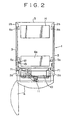
- FIGs. 1 to 3 there is shown an automatic cassette changer to which the present invention is applied.
- the automatic cassette changer is constructed for video cassettes for a television broadcasting station.
- the automatic cassette changer includes an automatic cassette changer body 1 formed as a vertically elongated housing which includes two pairs of front and rear support posts 2a and 2b and an outer shell 3 covering the opposite left and right sides and the rear side of the housing with the front side opened.
- a door 4 is disposed at the front side of the housing of the changer body 1.
- Two pairs of mounting frames 5a and 5b are disposed vertically between the front and rear support posts 2a and 2b.
- a plurality of, four in the arrangement shown, types of cassette accommodating rack units 6a to 6d are accommodated at vertically different stages at an upper location in the changer body 1, and a plurality of, two in the arrangement shown, types of video tape recorders 7a and 7b serving as recording and/or reproducing apparatus and so forth are accommodated at a lower location in the changer body 1.
- the cassette accommodating rack units include three cassette accommodating rack units 6a, two cassette accommodating rack units 6b, one cassette accommodating rack unit 6c and one cassette accommodating rack unit 6d.
- the video tape recorders include one video tape recorder 7a and two video tape recorders 7b.
- the small, medium and large size cassettes 9b, 9c and 9d are formed equal in thickness but are different in outer diameter from one another.
- the video tape recorder 7a is formed as a digital video tape recorder which can selectively record and/or reproduce the small, medium and large size cassettes 9b, 9c and 9d while the video tape recorders 7b are formed as 8 mm video tape recorders which can record and/or reproduce the 8 mm tape cassettes 9a.
- the cassette accommodating rack units 6a to 6d and the video tape recorders 7a and 7b are disposed in a vertical column in such a condition that the front faces thereof are directed forwardly of the changer body 1 (downwardly in Fig. 2) and held in register with one another in a vertical plane.
- a self-travelling transporting machine 10 is moved upwardly or downwardly along the front faces of the cassette accommodating rack units 6a to 6d and the video tape recorders 7a and 7b.
- the transporting machine 10 includes a hand block 11 for transferring a tape cassette.
- a plurality of type detecting sections 12 representative of the types of the cassette accommodating rack units 6a to 6d and the video tape recorders 7a and 7b are disposed in a vertical column on the left side of the front faces of the cassette accommodating rack units 6a to 6d and the video tape recorders 7a and 7b (on the left side in Fig. 1), and a type detecting sensor 13 which may be, for example, a photocoupler for reading the type detecting sections 12 is mounted on the transporting machine 10.
- a control box 14 for controlling the video tape recorders 7a and 7b and the transporting machine 10 is accommodated in the changer body 1.
- the designated tape cassettes 9a to 9d are manually accommodated in advance in the cassette accommodating racks 8a to 8d of the cassette accommodating rack units 6a to 6d, respectively.
- the transporting machine 10 is moved upwardly or downwardly while the type detecting sections 12 are scanned by the type detecting sensor 13 to detect the type of each of the cassette accommodating racks 8a to 8d and the video tape recorders 7a and 7b. Then, a designated one of the tape cassettes 9a to 9d is automatically pulled out from a designated one of the cassette accommodating racks 8a to 8d by means of the hand block 11 of the transporting machine 10.
- the hand block 11 of the transporting machine 10 transports the thus pulled out tape cassette 9a, 9b, 9c or 9d to a designated one of the video tape recorders 7a and 7b and automatically inserts it into a cassette insertion opening 15a or 15b of the video tape recorder 7a or 7b so as to thereafter perform recording and/or reproduction of the tape cassette 9a, 9b, 9c or 9d.
- the sequence of operations will be repeated so that continuous video signal reproduction, recording, edition or the like may be performed over a long period of time while suitably using the tape cassettes 9a to 9d wherein the recording formats, the sizes and so forth are different from one another.
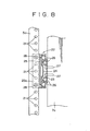
- Each of the two pairs of front and rear vertical mounting frames 5a and 5b shown in Fig. 7 has a large number of threaded mounting holes 21 formed at a fixed pitch as shown in Fig. 8 on the front face and an inner side face thereof.
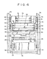
- the large size video tape recorder 7a for common use with the small, medium and large size tape cassettes 9b, 9c and 9d is formed as a unit and has a pair of left and right slide rails 22 mounted horizontally on the opposite left and right side faces of the video tape recorder 7a.
- Each of the slide rails 22 is formed from, as shown in Fig. 8, three rails including an inner rail 23, an intermediate rail 24 and an outer rail 25 and a large number of balls 26 interposed doubly between the rails 23 and 24 and between the rails 24 and 25.
- the inner rails 23 are secured horizontally to the opposite left and right sides of the video tape recorder 7a by means of a plurality of screws 27 while the outer rails 25 are removaly secured to the mounting holes 21 of the front mounting frames 5a by means of a plurality of screws 28 with a pair of front and rear brackets 25a interposed therebetween.
- a pair of left and right brackets 29 are securely mounted on the opposite left and right side portions of the front face side of the video tape recorder 7a and are removably secured to a plurality of mounting holes 21 on the front face side of the pair of left and right mounting frames 5a on the front face side by means of a plurality of screws 30 so as to exchangeably mount the video tape recorder 7a at a predetermined position in the changer body 1. It is to be noted that a type detecting section 12 is mounted on the front face of the left bracket 29 at a predetermined vertical position.
- the video tape recorder 7a can be exchanged freely for another video tape recorder of a different type by removing the screws 30 for the left and right brackets 29, slidably moving the intermediate rails 24 between the inner rails 23 and the outer rails 25 of the left and right slide rails 22 by way of the balls 26 and removing the video tape recorder 7a in one of the directions indicated by a double-sided arrow mark a as indicated by chain lines in Figs. 6 and 7 from the changer body 1.
- the video tape recorder 7a having a great weight can be slidably moved lightly in the directions of the arrow mark a by means of the balls 26 of the slide rails 22.
- the cassette accommodating rack units 6a to 6d will be described subsequently with reference to Figs. 9 to 16.
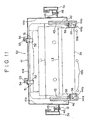
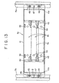
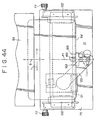
- the cassette accommodating rack unit 6d for accommodating the large size cassettes 9d therein is shown.
- the cassette accommodating rack unit 6d includes a pair of left and right vertical rack frames 42 mounted on the opposite left and right inner sides of a unit body 41 in a spaced relationship from each other by a great distance equal to the widthwise dimension, that is, the dimension in the leftward and rightward directions, of the large size tape cassettes 9d.
- the cassette accommodating rack unit 6d further includes three horizontal rack plates 43 formed in an opposing relationship to each other at three vertical stages on the opposing faces of the rack frames 42 thereby to form three cassette accommodating racks 8d disposed at three vertical stages. It is to be noted that each of the rack frames 42 and the rack plates 43 has a cassette guiding tapered face 44a or 44b formed at the front end, that is, an opening end of each of the cassette accommodating racks 8d.
- a pair of left and right brackets 45 are securely mounted on the opposite left and right side portions of the front face side of a pair of left and right side plates 41a of the unit body 41 and are removably secured to a plurality of screw holes 21 on the front face sides of the front side left and right mounting frames 5a each by means of a pair of upper and lower screws 46 so that the cassette accommodating rack unit 6d is exchangeably mounted at a desired position in the vertical direction in the changer body 1.
- the left and right brackets 45 are fitted on a pair of ones of a plurality of left and right positioning pins 47 mounted at a pitch equal to that of the mounting holes 21 on the front face sides of the left and right mounting frames 9a to effect positioning of the cassette accommodating rack unit 6d in the vertical direction and the leftward and rightward directions.
- a type detecting section 12 is mounted at a predetermined vertical position on the front face side of the left side bracket 45.
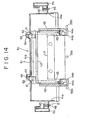
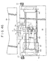
- Figs. 13 and 14 show the cassette accommodating rack unit 6c for accommodating the medium size tape cassettes 9c therein.
- the cassette accommodating rack unit 6c is constructed similarly to the cassette accommodating rack unit 6d except that it includes a unit body 41 having the same configuration as the cassette accommodating rack unit 6d and a pair of left and right rack frames 42 mounted in the unit body 41 in a spaced relationship by a medium distance equal to the length of the medium size tape cassettes 9c in the leftward and rightward directions.
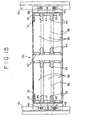
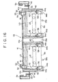
- Figs. 15 and 16 show a cassette accommodating rack unit 6b for storing the small size cassettes 9b therein.
- the cassette accommodating rack unit 6b is constructed similarly to the cassette accommodating rack unit 6d except that it includes a unit body 41 having the same configuration as that of the cassette accommodating rack unit 6d and two pairs of left and right rack frames 42 mounted in the unit body 41 in a spaced relationship by a small distance equal to the length of the small size tape cassettes 9b in the leftward and rightward directions thereby to form a total of six horizontal cassette accommodating racks 8b disposed in three stages in two vertical columns.
- the unit bodies 41 have an equal size and are mounted in the same manner on the mounting frames 5a and 5b. Consequently, the cassette accommodating rack units 6b to 6d can be freely exchangeably mounted at desired positions within the changer body 1.
- the small, medium and large size cassettes 9b to 9d are accommodated in the cassette accommodating racks 8b to 8d of the cassette accommodating rack units 6b to 6d, respectively.
- a plurality of types of tape cassettes 9a to 9d wherein the recording formats of the tapes and the sizes are different from one another and a plurality of types of video tape recorders 7a and 7b for recording and/or reproducing the tape cassettes 9a to 9d can be set in position freely and very readily as desired by the user.
- the cassette accommodating units 6a have the same size as the cassette accommodating rack units 6b to 6d and are exchangeably mounted on the mounting frames 5a in the same mounting manner.
- the cassette accommodating rack units 6a are each constructed such that a total of twelve 8 mm tape cassettes 9a having a comparatively small thickness can be accommodated, for example, in four rows and in three columns therein.
- the video tape recorders 7b are exchangeably mounted on the mounting frames 5a by the same mounting method as that for the cassette accommodating rack units 6a to 6d.
- a type detecting section 12 is mounted on the front face of the left bracket 45 of each of the cassette accommodating rack units 6a to 6d at a predetermined vertical position. Wrong Cassette Insertion Discriminating Mechanism for Cassette Accommodating Rack
- the distances L1, L2, L3, L4 and L5, L6 in the leftward and rightward directions between the rack frames 42 and the rack plates 43 constituting the cassette accommodating racks 8b to 8d of the cassette accommodating rack units 6b to 6d are set to three sizes in accordance with the lengths of the small, medium and large size cassettes 9b, 9c and 9d in the leftward and rightward directions, respectively.
- a pair of left and right error insertion preventing levers 51 are mounted on a rear face plate 41b of the unit body 41 of each of the cassette accommodating rack units 6b to 6d within the same height as the cassette accommodating rack 8b, 8c or 9d.
- the error insertion preventing levers 51 are mounted on the rear face plate 41b for pivotal motion in the upward and downward directions indicated by arrow marks b and b' each by means of a horizontal fulcrum pin 52, and a shutter 53 is formed integrally at a rear end of each of the error insertion preventing lever 51.
- Each of the error insertion preventing levers 51 is pivoted in the direction of the arrow mark b by its own weight until it stops in a horizontal position.
- a pair of cassette sensors 54 each in the form of, for example, a photocoupler are mounted on the rear face plate 41b and is each switched on or off by the shutter 53 of the corresponding error insertion preventing lever 51.
- a pair of rubber cushions 55 are mounted on the inner side face of the rear face plate 41b within the same height as the cassette accommodating rack 8b, 8c or 9d, and a cassette stopper 56 is mounted at a front end of each of the rack plates 43 for pivotal motion in the upward and downward directions indicated by arrow marks c and c' each by means of a horizontal fulcrum pin 57 and is normally urged to pivot in the direction of the arrow mark c' by a torsion spring 58.
- Three sets of cassette protrusion sensors 59a and 59b common to all of the cassette accommodating rack units 6a to 6d are disposed in a vertically opposed relationship to each other at a central portion and the opposite left and right portions of the front face sides of the cassette accommodating rack units 6a to 6d.
- Each of the cassette protrusion sensors 59a and 59b is constituted from a photo-sensor consisting of a light emitting element and a light receiving element.
- a cut face 92 is formed at an upper portion of the front end face 91 of the tape cassette 9d.
- the left and right error insertion preventing levers 51 ride on the cut face 92 of the tape cassette 9d as seen at the lower stage of Fig. 12 so that they are pushed up by the latter in the direction of the arrow mark b', whereupon the shutters 53 thereof turn off the left and right cassette sensors 54 at a time. Consequently, it is detected by the left and right cassette sensors 54 that the tape cassette 9d has been inserted correctly onto the cassette accommodating rack 8d. In particular, the left and right cassette sensors 54 detect the cut face 92 of the tape cassette 9d.
- the left and right error insertion preventing levers 51 cannot ride on the cut face 92 of the tape cassette 9d, and consequently, the left and right cassette sensors 54 maintain their on state, thereby detecting wrong insertion of the tape cassette 9d.
- the three sets of cassette protrusion sensors 59a and 59b maintain their off state, thereby detecting protrusion of the tape cassette 9d.
- a cassette for the 1/2 inch tape which has the same leftward and rightward size as the 3/4 inch digital tape cassettes 9b, 9c and 9d could be inserted in error onto the pair of left and right rack plates 43 of any of the cassette accommodating racks 8b to 8d.
- the 1/2 inch tape cassette since the 1/2 inch tape cassette has a smaller thickness than the 3/4 inch tape digital cassettes 9b, 9c and 9d, it cannot push up the left and right error insertion preventing levers 51 in the direction of the arrow mark b' to turn off the left and right cassette sensors 54 at a time. Consequently, insertion of a wrong tape cassette in error can still be detected.
- the automatic cassette changer since the tape cassettes 9a to 9d of different types wherein the recording formats of the tapes, the sizes and so forth are different from one another are accommodated and selectively recorded and/or reproduced by means of the video tape recorders 7a and 7b for exclusive use for them while it can be prevented to insert, into one of the cassette accommodating racks 8a to 8d of different types, a tape cassette which does not match the cassette accommodating rack in format, size or the like, an otherwise possible trouble that the transporting machine 10 inserts a wrong tape cassette 9a, 9b, 9c or 9d into a wrong video tape recorder 7a or 7b does not occur at all.
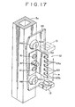
- a type detecting section 12 and a type detecting sensor 13 will be described subsequently with reference to Figs. 17 and 18.
- the type detecting sections 12 are disposed in a vertical column on the left side of the front faces of the cassette accommodating rack units 6a to 6d and the video tape recorders 7a and 7b.
- Each of the type detecting sections 12 includes a vertical plate 62 securely mounted on the front face of a bracket 29 or 45 at a predetermined vertical position by means of a pair of upper and lower fastening screws 61.
- a plurality of signal elements 63 are formed in a vertical column along an end of the vertical plate 62 and indicate the type of the corresponding cassette accommodating rack unit 6a, 6b, 6c or 6d or video tape recorder 7a or 7b.
- the signal elements 63 are formed from recesses 63a and projections or tabs 63b and indicate 5-bit data representative of one of 32 different types which may represent the types of the cassette accommodating rack units 6a to 6d and the video tape recorders 7a and 7b.
- the type detecting sensor 13 in the form of a photo-coupler mounted on the transporting machine 10 scans the signal elements 63 of the vertical plate 62 in the upward and downward directions indicated by a double-sided arrow mark e to read a "1" signal at each recess 63a and a "0" signal at each projection 63b of the signal elements 63 to discriminate the type represented by the signal elements 63 of the vertical plate 62 as 5-bit data.
- the vertical position of the cassette accommodating rack unit 6a, 6b, 6c or 6d or video tape recorder 7a or 7b is detected by an upper edge 62a (or alternatively a lower edge 62b) of the vertical plate 62, and a designated cassette accommodating rack 8a, 8b, 8c or 8d in the cassette accommodating rack unit 6a, 6b, 6c or 6d or the position of the cassette insertion opening 15a or 15b of the video tape recorder 7a or 7b is retrieved by counting the signal elements 63 of the vertical plate 62 downwardly (or upwardly) from the vertical position thus detected. It is to be noted that, as shown in Fig.
- an origin sensor 86 is mounted on one of a pair of brackets 83a of the transporting machine 10, and a pair of detecting sections 87 indicative of an origin and upper and lower limits of the transporting machine 10 are mounted at the opposite upper and lower ends of one of the mounting frames 5.
- an initializing operation is performed wherein the transporting machine 10 is moved upwardly and downwardly once until the origin sensor 87 detects the origin detecting section 87, whereupon the transporting machine 10 is stopped. Thereafter, the position of any of the cassette accommodating racks 8a to 8d and the video tape recorders 7a and 7b will be retrieved.
- the transporting machine 10 can automatically discriminate the type of the newly installed equipment.
- a pair of left and right racks 71 are disposed vertically over the entire area of the spacing of movement of the transporting machine 10 in the vertical direction.
- a pair of slide rails 72 and a pair of fixed rails 73 are mounted vertically on a pair of left and right mounting frames 74a and 74b rearwardly of the left and right racks 71, respectively.
- a pinion shaft 76 is mounted horizontally at a rear portion of a transporting machine body 75 and extends leftwardly and rightwardly through the transporting machine body 75.
- a pair of left and right pinions 77 are securely mounted at the opposite left and right ends of the pinion shaft 76 and held in meshing engagement with the left and right racks 71, respectively.
- each of the slide rails 72 includes a vertical slider guide 78 securely mounted on one of the mounting frames 74a and having a substantially channel-shaped cross section, and a slider 79 mounted for sliding movement in the vertical direction in the slider guide 78.
- a large number of balls 81 are loosely fitted in a pair of vertically elongated front and rear circular slots 80 formed in the slider 79 and are also loosely fitted in a pair of guide grooves 82 formed on a pair of opposing faces of the slider guide 78 in the forward and backward directions.
- a movement (i.e., a play) of the slider 79 in the slider guide 78 in the leftward or rightward direction (the direction indicated by a double-sided arrow mark f) and the forward or backward direction (the direction indicated by a double-sided arrow mark g) is restricted by the guide grooves 82 so that the slider 78 can be slidably moved smoothly only in the upward and downward directions of the arrow mark e within the slider guide 79.
- a pair of left and right brackets 83a and 83b are securely mounted at the opposite left and right end portions of a rear portion of the transmitting apparatus body 75, and the slider 79 is securely mounted on the outer side of the bracket 83a.
- each of the left and right travel guides 85a and 85b is constituted from the slide rail 72, the fixed guide rail 73 and the guide rollers 84.
- a motor 95 serving as driving means is mounted in the transporting machine body 75 by way of a bracket 94, and a gear 96 is securely mounted on a shaft 95a of the motor 95 and held in meshing engagement with another gear 98 securely mounted on an intermediate shaft 97.
- the intermediate shaft 97 extends perpendicularly to the pinion shaft 87, and a worm 99 is securely mounted on the intermediate shaft 97 and held in meshing engagement with a worm wheel 100 securely mounted on the pinion shaft 76.
- the intermediate shaft 97 is supported on a substantially channel-shaped mounting frame 101 mounted on the inner side of the transporting machine body 75.
- a pair of left and right cassette slide guides 102 are mounted horizontally at upper portions of the opposite left and right ends of the transporting machine body 75.
- the left and right pinions 77 are driven to rotate by the motor 95 by way of the gears 96 and 98, intermediate shaft 97, worm 99, worm wheel 100 and pinion shaft 76, whereupon the pinions 77 are rolled in the vertical direction of the arrow mark f along the left and right racks 71 to cause the transporting machine 10 to travel smoothly at a high speed in the vertical direction of the arrow mark e under the guidance of the left and right travel guides 85a and 85b.
- one of the left and right travel guides 85a and 85b of the transporting machine 10 is constituted from the slide rail 72 while the other is constituted from the fixed guide rail 73 and the guide rollers 84, and the movements (plays) of the transporting machine 10 in the leftward and rightward directions (the directions of the arrow mark f) and the forward and backward directions (the directions of the arrow mark g) are restricted by the slide rail 72.
- deformation in the form of a bend of the left or right mounting frame 74a or 74b is absorbed by a slip of the guide rollers 84 in the directions of the arrow mark f with respect to the fixed rail 73 of the other travel guide 85b. Accordingly, even if any of the left and right mounting frames 74a and 74b has some bend or the like, the transporting machine 10 can travel and be guided smoothly without fail, and besides, a save of the spacing can also be achieved.
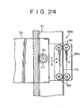
- a widthwise restricting mechanism 113 including a fixed rail 111 extending in parallel to the directions of the arrow mark g and a total of four guide rollers 112 disposed in left and right pairs and in upper and lower pairs and adapted to be contacted with the opposite left and right side faces of the fixed rail 111 and a depthwise restricting mechanisms 114 including a fixed rail 114 extending in parallel to the directions of the arrow mark f and a total of four guide rollers 115 disposed in left and right pairs and in upper and lower pairs and adapted to be contacted with the opposite front and rear faces of the fixed rail 114.
- the fixed rails 111 and 114 and the guide rollers 112 and 115 are individually required by a great number, which makes the structure of the entire arrangement complicated and makes the cost of the arrangement high.
- the spacing S1 in the widthwise or leftward and rightward directions and the spacing S2 in the thicknesswise or forward and backward directions must be great as much.
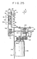
- the travel guide 85a which employs the guide rail 72 as shown in Fig. 25 can make the widthwise spacing S3 and the thicknesswise spacing S4 very small comparing with the widthwise spacing S1 and the thicknesswise spacing S2 shown in Fig. 27, respectively. Further, since the movements of the transporting machine 10 in the widthwise direction (the directions indicated by the arrow mark f) and the thicknesswise direction (the directions indicated by the arrow mark g) can be restricted readily by the slide rail 72 of the travel guide 85a, the other travel guide 85b is required only to restrict the movement of the transporting machine 10 in the thicknesswise direction (the directions indicated by the arrow mark g), and consequently, the fixed rail 111 and the four guide rollers 112 shown in Fig. 27 can be omitted.
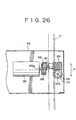
- the hand block 11 mounted at an upper portion of the transporting machine body 75 is mounted for movement in two planes including a plane of the directions of the arrow mark g which is the direction in which a tape cassette is to be inserted into or removed from any of the cassette according racks 8a to 8d and the video tape recorders 7a and 7b and another plane of the directions of the arrow mark f which is a direction perpendicular to the cassette inserting or removing direction by means of a slider 121 serving as a driving member and a pivotal arm 122.
- a feed screw 124 and a guide rod 125 are mounted horizontally in parallel to the directions of the arrow mark f on and between a pair of left and right mounting plates 123 securely mounted in the transporting machine body 75, and a nut 126 and a thrust bearing 127 are mounted horizontally on the slider 121 and held fitted on the feed screw 124 and the guide rod 125, respectively.
- a timing pulley 129 is securely mounted on a shaft 128a of a motor 128 mounted in the transporting machine body 75 while another timing pulley 130 is securely mounted at an end portion of the feed screw 124, and a timing belt 131 extends between and around outer peripheries of the timing pulleys 129 and 130.
- the feed screw 124 is thus driven to rotate by the motor 128 by way of the timing belt 131 to feed the nut 126 to slidably move the slider 121 linearly in either of the directions of the arrow mark f along the guide rod 125.
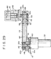
- a motor 132 with a speed reducer is mounted in upward orientation at a lower portion of the slider 121, and the horizontal pivotal arm 122 is securely mounted at an end 122a thereof on an output shaft 132a extending vertically upwardly from an upper end of the motor 132.
- the hand block 11 is mounted at an upper portion of the other end 122b of the pivotal arm 122 by way of a vertical mounting shaft 133.
- the pivotal arm 122 is thus driven to pivot in either of the directions indicated by a double-sided arrow mark h integrally with the output shaft 132a of the motor 132.
- the hand block 11 is thus moved linearly in either of the directions of the arrow mark f by means of the slider 122, and the hand block 11 is moved linearly in either of the directions of the arrow mark g by a composite movement of the pivotal motion of the pivotal arm 122 in either of the directions of the arrow mark h and the linear movement of the slider 121 in either of the directions of the arrow mark f.
- the motor 132 with a speed reducer is mounted vertically in upward orientation at a lower portion of the slider base 121a of the slider 121 by means of a plurality of screws 141, and the output shaft 132a of the motor 132 extends vertically upwardly above the slider base 121a.
- a flanged sleeve 142 is securely mounted at an outer periphery of the output shaft 132a of the motor 132 by means of a plurality of screws 143, and the horizontal pivotal arm 122 is securely mounted at the end 122a thereof on the flange 141a of the sleeve 142 by means of a plurality of screws 144.
- a cylindrical shaft 145 is fitted coaxially in a spaced relationship on an outer periphery of the sleeve 142 and is securely mounted on the slider base 121a by means of a plurality of screws 146, and the outer periphery of the sleeve 142 is supported on an inner periphery of the upper end of the cylindrical shaft 145 by way of a bearing 147.
- a fixed timing pulley 148 is formed on the outer periphery of the top end of the cylindrical shaft 145.
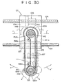
- a lower end 133a of the vertical mounting shaft 133 is fitted from above with the other end of the pivotal arm 122 and is supported for rotation at two vertically spaced portions thereof by an upper oil-impregnated bearing 151 and a lower bearing 152.
- a mounting plate 153 for the lower bearing 152 is mounted on a pair of mounting bases 154 of the pivotal arm 122 by means of a plurality of screws 155.
- a rotary timing pulley 156 having the same diameter as the fixed timing pulley 148 is securely fixed, for example, by force fitting to an outer periphery of a portion of the lower end 133a of the mounting shaft 133 between the oil-impregnated bearing 151 and the bearing 152, and a timing belt 157 serving as rotation controlling means extend between and around the outer peripheries of the fixed timing pulley 148 and the rotary timing pulley 156.
- the timing belt 157 is held in a taut condition by means of a pair of tension pulleys 158a and 158b mounted on the pivotal arm 122.
- the pivotal arm 122 is formed as a cover which covers over the outer peripheries of the fixed timing pulley 148, the rotary timing pulley 156 and the timing belt 157.
- An encoder for detecting an angular position of the pivotal arm 122 is constituted from a plurality of sensors 161 in the form of photo-couplers or the like mounted on the slider base 121a on the outer periphery of the cylindrical shaft 145 and a rotary plate 162 mounted for rotation together with the pivotal arm 122.
- a mounting arm 159 is securely mounted horizontally on the mounting shaft 133 by means of a screw 163, and a turning motion preventing pin 160 is mounted vertically at an upper portion of an end of the arm 159.
- a vertical mounting hole 164 is formed in the hand block 11, and a pair of upper and lower sleeves 165 are mounted in the mounting hole 164.
- a groove 167 is formed at an end of a projection 166 extending horizontally from a portion of the hand block 11 in the proximity of the mounting hole 164.
- the hand block 11 is fitted from above on the outer periphery of the mounting shaft 133 adjacent the upper end 133b with the sleeves 165 interposed therebetween until it is abutted with the arm 159, and the turning motion preventing pin 160 is fitted in the groove 167 of the projection 166. Accordingly, the hand block 11 is turned integrally with the mounting shaft 133 by way of the turning motion preventing pin 160. It is to be noted that the entire hand block 11 is mounted for upward and downward movement in the directions indicated by arrow marks i and i' with respect to the mounting shaft 133 and the turning portion preventing pin 160.
- the pivotal arm 122 is driven to pivot forwardly or reversely in the direction of the arrow mark h or h' integrally with the output shaft 132a.
- the pivotal arm 122 is pivoted on the outer periphery of the fixed timing pulley 148 securely mounted on the slider base 121a, the phase of the timing belt 157 on the outer periphery of the fixed timing pulley 148 is varied in accordance with the pivotal motion of the pivotal arm 122.
- the timing belt 157 drives the mounting shaft 133 by way of the rotary timing pulley 156 to rotate by the same angle as the output shaft 132a in the direction indicated by an arrow mark k or k' which is the opposite direction to the direction of rotation of the output shaft 132a. Then, the mounting shaft 133 in turn drives the hand block 11 to turn in the direction of the arrow mark k or k' by way of the turning motion preventing pin 160.
- the hand block 11 can be moved linearly in parallel to the directions of the arrow mark g which is the cassette inserting or removing direction while keeping the posture parallel to the directions of the arrow mark f (in the posture wherein the hand block 11 is always kept directed in parallel to the cassette accommodating racks 8a to 8d and the video tape recorders 7a and 7b) due to a composite movement of the pivotal motion and the linear movement.
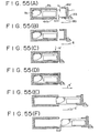
- Fig. 33(A) to 33(C) by synchronizing the pivotal motion of the pivotal arm 122 in the direction of the arrow mark h or h' and the linear movement of the slider 121 in either of the directions of the arrow mark f with each other as seen from Figs. 33(A) to 33(C)
- the hand block 11 can be moved linearly in parallel to the directions of the arrow mark g which is the cassette inserting or removing direction while keeping the posture parallel to the directions of the arrow mark f (in the posture wherein the hand block 11 is always kept directed in parallel to the cassette accommodating racks
- FIG. 33(A) shows different successive stages of a series of movements of the hand block 11 when it linearly moves in parallel to the directions of the arrow mark g on the center line P1 of the transporting machine 10;
- Fig. 33(B) shows different successive stages of a series of movements of the hand block 11 when it linearly moves in either of the directions of the arrow mark g on a right side line P2 of the transporting machine 10;
- Fig. 33(C) shows different successive stages of a series of movements of the hand block 11 when it linearly moves in parallel to either of the directions of the arrow mark g on a left side line P3 of the transporting machine 10.
- the hand block 11 can be moved linearly in parallel to the directions of the arrow mark g at any position between the left and right side lines P3 and P2, the position at which a tape cassette 9a, 9b, 9c or 9d is to be transferred to or from any of the cassette accommodating racks 8a to 8d and the video tape recorders 7a and 7b can be selected freely in the directions of the arrow mark f between the left and right side lines P3 and P2.
- the hand block 11 can be linearly moved with the greatest stroke in the directions of the arrow mark g while keeping the posture wherein it is directed in parallel to the cassette accommodating racks 8a to 8d and the video tape recorders 7a and 7b.
- the pivotal arm 122 is only pivoted within a small spacing in the direction of the arrow mark h or h' around the slider 121.
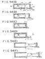
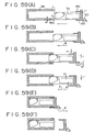
- two left and right columns of representations of Fig. 34(A) illustrate spacings required for movements of the pivotal arm 122 when a small size or 8 mm tape cassette 8a and a large size tape cassette 8d are inserted or removed, respectively, in either of the directions of the arrow mark g by the hand block 11 of the automatic cassette changer. Meanwhile, two left and right columns of representations of Fig.
- 34(B) illustrate required spacings occupied by the second feeding mechanism 72 when a small size tape cassette 8a and a large size tape cassette 8d are inserted or removed, respectively, in either of the directions of the arrow mark g by the hand block 11 where the feeding mechanism for the hand block 11 is divided into the first feeding mechanism 71 in the form of a feed screw and so forth for feeding the hand block 11 in the directions of the arrow mark g and the second feeding mechanism 72 in the form of a feed screw and so forth for feeding the hand block 11 in the directions of the arrow mark g. If the two cases are compared with each other, then it is apparent that the spacing for movement of the pivotal arm 22 can be reduced by an amount corresponding to the spacing S5 in the directions of the arrow mark g comparing with the spacing occupied by the second feeding mechanism 72.
- timing belt 57 is employed as rotation controlling means for the mounting shaft 133 in the arrangement described above, the fixed timing pulley 148 and the rotary timing pulleys 156 may be replaced by gears which are interconnected by a gear train.
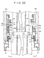
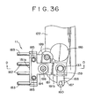
- the hand block 11 includes a hand block body 181 which has a substantially T shape in plan and has a vertically elongated rectangular shape in front elevation.
- Two pairs of left and right horizontal cassette holding pins 182 and 183 are mounted horizontally on the front face 181 of the hand block body 181 in a spaced relationship in the vertical direction which is a cassette thicknesswise direction.
- the upper left and right cassette holding pins 182 are spaced by a smaller distance in the leftward and rightward directions in Fig. 35 and are securely mounted perpendicularly on the front face of a vertical slider 184 so that they can be moved upward and downwardly in the directions indicated by arrow marks m and m' together with the slider 184.
- the lower left and right cassette holding pins 183 are spaced by a greater distance in the leftward and rightward directions and are securely mounted perpendicularly at the opposite left and right side positions of the front face 181a of the hand block body 181.
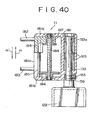
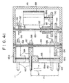
- a pair of left and right guide shafts 185 and a feed screw 186 are mounted vertically in a triangular arrangement in plan between a pair of upper and lower walls 181b and 181c in the hand block body 181.
- the slider 184 is fitted for upward and downward movement on the left and right guide shafts 185 with thrust bearings 184a interposed therebetween, and a nut 187 is secured to the slider 184 and held in threaded engagement with the feed screw 186.
- a motor 188 and a vertical intermediate shaft 189 are mounted in the hand block body 181, and a gear 190 is securely mounted on a shaft 188a of the motor 188 and held in meshing engagement with a torque limiter gear 191 loosely fitted on the intermediate shaft 189.
- a torque limiter 192 is interposed between the torque limiter gear 191 and the intermediate shaft 189, and a gear 193 is securely mounted on the intermediate shaft 189 and is held in meshing engagement with another gear 194 securely mounted on the feed screw 186.
- an encoder 197 serving as opening amount controlling means is constituted from a shutter disk 195 securely mounted on the intermediate shaft 189 and a sensor 196 in the form of a photo-coupler or the like mounted in the hand block body 181.
- An upper limit sensor 199 and a lower limit sensor 200 are mounted in the hand block body 181 such that they are turned on or off by a shutter plate 198 mounted on the slider 184 to detect an upper limit position and a lower limit position of the cassette holding pins 182, respectively.
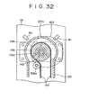
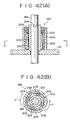
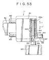
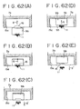
- FIGs. 42(A) and 42(B) An exemplary form of the torque limiter 192 is shown in Figs. 42(A) and 42(B).
- the torque limiter 192 shown is formed as a roller type torque limiter wherein a cylindrical outer ring 202 is securely mounted by force fitting or like means in a cylindrical portion 191a formed integrally on the torque limiter gear 191, and a cylindrical inner ring 203 is fitted on an outer periphery of the intermediate shaft 189 and is securely mounted on the intermediate shaft 189 by means of a pin 204.
- a plurality of, for example, four, rollers 205 are inserted in parallel to the intermediate shaft 189 between the outer and inner rings 202 and 203 and are normally biased such that they are resiliently pressed between the outer peripheral face of the inner ring 203 and four wedge-shaped friction faces 204 formed on the inner circumferential face of the outer ring 202 by four compression coil springs 207 accommodated in four recesses 206 of the outer ring 202.
- a closing member 209 is mounted at the open end of the cylindrical portion 191a of the torque limiter gear 191.
- the torque limiter 192 transmits, when the torque limiter gear 191 on the input side is driven to rotate in the direction indicated by an arrow mark n, the torque of rotation to the intermediate shaft 189 by way of the rollers 205.
- the intermediate shaft 189 is rotated integrally with the torque limiter gear 191
- a rotational slip of the intermediate shaft 189 with respect to the torque limiter gear 191 is produced by a slip of the rollers 205 with respect to the friction face 208.
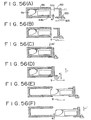
- the motor 188 When the power is made available with the automatic cassette changer, the motor 188 is energized to rotate forwardly so that the feed screw 186 is driven to rotate forwardly by way of the gears 190 and 191, torque limiter 192, intermediate shaft 189 and gears 193 and 194. Consequently, the slider 184 is moved downwardly in the direction indicated by an arrow mark m' under the guidance of the left and right guide shafts 185 by a screw feeding operation of the nut 187 by the feed screw 186, and thereupon, the cassette holding pins 182 are moved downwardly in parallel in the direction of the arrow mark m' integrally with the slider 184. Then, the position at which the lower limit sensor 200 detects the shutter plate 198 is the origin corresponding to the lower limit position of the cassette holding pins 182, and when the left and right cassette holding pins 182 comes to the origin, the motor 188 is stopped.
- the motor 188 is rotated reversely so that the feed screw 186 is driven to rotate reversely. Consequently, the slider 184 is moved upwardly in the direction indicated by an arrow mark m under the guidance of the left and right guide shafts 185 by a screw feeding operation of the nut 187 by the feed screw 186, and the cassette holding pins 182 are moved upwardly in parallel in the direction of the arrow mark m integrally with the slider 184 so that they are opened upwardly with respect to the cassette holding pins 183.
- the direction of rotation of the torque limiter 192 then is the direction indicated by the arrow mark n' shown in Fig. 42(B) so that the intermediate shaft 189 is rotated in a non-slipping condition.
- the opening amount H1 of the cassette holding pins 182 with respect to the cassette holding pins 183 is counted accurately by means of the encoder 197.
- the opening amount H1 of the cassette holding pins 182 with respect to the cassette holding pins 183 is adjusted, depending upon the count value of the encoder 197, to a predetermined value in accordance with the thickness information of the tape cassette, whereupon the motor 188 is stopped. It is to be noted that otherwise possible runaway of the slider 184 in the direction of the arrow mark m is prevented by the upper limit sensor 199.
- the opening amount H1 of the cassette holding pins 182 with respect to the cassette holding pins 183 was adjusted to an optimum value in accordance with the thickness of the designated tape cassette to be held, and consequently, only if the cassette holding pins 182 are moved downwardly in the direction of the arrow mark m' by a very small distance after the designated tape cassette has been inserted horizontally between the cassette holding pins 182 and 183, the tape cassette can be held in a moment between the cassette holding pins 182 and 183 irrespective of the thickness of the tape cassette. Accordingly, even if the thickness of a cassette to be held varies every time, a holding operation for the tape cassette having any of the several thicknesses can always be performed rapidly.
- a tape cassette having any thickness can be held always stably by a holding force of a fixed magnitude, and an otherwise possible accident that the holding force to a tape cassette is so great due to a thickness of the tape cassette as to inadvertently damage the tape cassette can be prevented.
- the feed screw 186 having high friction is employed at the last stage of the driving system for driving the cassette holding pins 182 linearly in the direction of the arrow mark m or m', even if the power supply to the automatic cassette changer is interrupted while a tape cassette is held between the cassette holding pins 182 and 183, such a trouble that the cassette holding pins 182 are pushed upwardly in the direction of the arrow mark m by the weight of the tape cassette itself to open inadvertently so that the tape cassette is let off from the cassette holding pins 182 and 183 does not occur at all.
- the holding force for a tape cassette can always be kept at a fixed value by the torque limiter 192 while the cassette holding force is applied in the direction of the arrow mark m' to the cassette holding pins 182 by the feed screw 186, when the tape cassette is held, such an accident that the nut 187 of the slider 183 bites into the feed screw 186 to lock the feed screw 186 does not occur at all.
- Fig. 43(A) shows an arrangement wherein two pairs of upper and lower cassette holding pins 211 and 212 are mounted for pivotal motion in the vertical directions indicated by a double-sided arrow mark o around fulcrums 213 and 214, respectively, on a hand block body 181 and a driving member 218 is driven to move in the directions indicated by a double-sided arrow mark p by way of a nut 217 by a feed screw 216 which is driven to rotate by a motor 215 so that the cassette holding pins 211 and 213 are driven to pivot in the directions of the arrow mark o opposite to each other around the fulcrums 213 and 214 by the driving member 218.
- the holding conditions for the tape cassettes 219 and 221 are very unstable, and there is a problem that the tape cassette 219 or 221 is let off readily from between the cassette holding pins 211 and 212 by slight vibrations or a like factor during transportation thereof between a cassette accommodating rack and a video tape recorder. It is another problem that an operation of inserting or removing such tape cassette into or from a cassette accommodating rack or a video tape recorder is not sure.
- the tape cassettes 9a to 9d having different thicknesses can be inserted and removed normally stably into and from the cassette accommodating racks 8a to 9d and the video tape recorders 7a and 7b, and besides, an operation of transporting a tape cassette 9a, 9b, 9c or 9d of a different thickness between the accommodating rack 8a, 8b, 8c or 8d and the video tape recorder 7a or 7b by the transporting machine 10 can be performed normally stably and with certainty. Consequently, such an otherwise possible accident that a tape cassette 9a, 9b, 9c or 9d during transportation is let off inadvertently from between the cassette holding pins 182 and 183 does not occur at all.
- the left and right cassette slide guides 102 are mounted horizontally at upper portions of the opposite left and right end portions of the transporting machine body 75 and are each formed from a belt-shaped plate having a predetermined width W1 and extending in parallel to the directions of the arrow mark g which are the cassette inserting and removing directions.
- the height H2 of the left and right cassette slide guides 102 with respect to the transporting machine body 75 is set to the height substantially in flush with upper end faces of the left and right cassette holding pins 183 at the lower portion of the hand block 11.
- the distances W2 and W3 between the outer sides and the inner sides of the left and right cassette slide guides 102 in the leftward and rightward directions, the width W4 of a large size tape cassette 9d having the greatest size in the leftward and rightward directions and the width W5 of a medium size tape cassette 9c having the second greatest size in the leftward and rightward directions are set so as to have the relationship W2 > W3 > W4 > W5.
- the tape cassette 9d since the large size tape cassette 9d has a great weight, it may be difficult to support the tape cassette 9d only by means of the two pairs of and a total of four cassette holding pins 182 and 183 of the hand block 11. Thereupon, however, the tape cassette 9d can be inserted or removed in such a manner that the opposite left and right ends thereof are placed on the left and right cassette slide guides 102 and the tape cassette 9d is slidably moved in either of the directions of the arrow mark g on the cassette slide guides 102. Consequently, the tape cassette 9d having a great weight can be inserted and removed smoothly and very stably. Further, as the tape cassette 9d is supported on the left and right cassette slide guides 102, the burden (load) to the cassette holding pins 182 and 183 is reduced as much, and accordingly, the safety is very high.
- an 8 mm tape cassette 9a, a small size tape cassette 9b or a medium size tape cassette 9c has a small weight comparing with a large size tape cassette 9d, and consequently, it can be inserted or removed in either of the directions of the arrow mark g while it is held sufficiently stably only by the four cassette holding pins 182 and 183 of the hand block 11 as seen from Fig. 46 or 47.
- the hand block 11 can be freely moved in the leftward and right directions indicated by the arrow mark f with a sufficient margin within the inner side distance W3 of the left and right cassette slide guides 102.
- the positions in which the tape cassettes 9a to 9d are accommodated with respect to the center line P1 of the transporting machine 10 can be set freely in the directions of the arrow mark f in such a manner that, for example, as shown in Fig. 1, the 8 mm tape cassettes 9a having the smallest size are accommodated in three vertical columns arranged in one horizontal row in a cassette accommodating rack unit 6a or the small size cassettes 9b having the second smallest size are accommodated in two vertical columns arranged in one horizontal row in a cassette accommodating rack unit 6b.
- the automatic cassette changer can accommodate therein all available types of tape cassettes for which the recording formats may be different from one another and can install all available types of video tape recorders for recording or reproducing the tape cassettes.
- a pair of left and right mounting plates 231 are securely mounted at locations of the opposite left and right side faces 181d of the hand block body 181 displaced to the front face 181 side.
- a pair of left and right cassette detecting levers 232 and 233 are mounted for pivotal motion in the directions indicated by arrow marks Q and Q' each around a fulcrum 234.
- Each of the cassette detecting levers 232 and 233 is normally biased to pivot in the direction of the arrow mark Q' by a tension spring 235, and when the cassette detecting levers 232 and 233 are abutted with respective stoppers 236 as indicated by a broken line in Fig.
- ends 232a and 233a thereof are projected a little forwardly in the direction of the arrow mark g from the front face 181a of the hand block body 181.
- a pair of left and right cassette inclination sensors 237 and 238 each in the form of a photo-coupler or the like are mounted on the left and right mounting plates 231 such that they are turned on or off by shutter plates 232b and 233b formed at rear end portions of the cassette detecting levers 232 and 233, respectively.
- the cassette inclination detecting mechanism when the upper and lower cassette holding pins 182 and 183 are to be inserted in the direction of the arrow mark g, for example, above and below a tape cassette 9b in order to hold the tape cassette 9b by and between the cassette holding pins 182 and 183 as shown in Figs. 48 and 50, if there is no inclination of the tape cassette 9b within a horizontal plane with respect to the hand block 11, the rear end face 93 of the tape cassette 9b is abutted in parallel with the front face 181a of the hand block body 181 as indicated by a solid line in Fig. 50.
- the left and right cassette detecting levers 232 and 233 are pivoted in the direction of the arrow mark Q against the tension springs 235 around the fulcra 234 by the rear end face 93 of the tape cassette 9b as indicated by a solid line in Fig. 48, whereupon the shutter plates 232a and 233a of the cassette detecting levers 232 and 233 are detected by the left and right cassette inclination sensors 237 and 238, respectively.
- both of the left and right cassette inclination sensors 237 and 238 detect the rear end face 93 of the tape cassette 9b, it is determined that there is no inclination of the cassette 9b within a horizontal plane with respect to the hand block 11.
- the cassette holding pins 182 are moved down in the direction of the arrow mark m' to hold the tape cassette 9b in its thicknesswise direction between the cassette holding pins 182 and 183.
- the entire hand block 11 is pressed in the direction of the arrow mark g against the tape cassette 9b to correct the posture of the tape cassette 9b so that the rear end face 9e of the tape cassette 9b may be abutted in parallel with the front face 181a of the hand block body 181.
- the dispersion in relative distance between the transporting machine 10 and the tape cassette 9b in the directions of the arrow marks g and g' is absorbed automatically.
- the cassette holding pins 182 are moved down in the direction of the arrow mark m' until the tape cassette 9b is held in the widthwise direction by and between the cassette holding pins 182 and 183.
- Figs. 51(A) to 51(E) there are shown different successive steps of an operation of removing, for example, a tape cassette 9b from a video tape recorder 7a.
- the tape cassette 9b discharged in the direction of the arrow mark g' from the cassette insertion opening 15a of the video tape recorder 7a does not always assume a fixed correct posture due to the structure of them, but in most cases presents an inclination within a horizontal plane with respect to the hand block 11 as seen in Fig. 51(A). Therefore, the rear end face 93 of the tape cassette 9b is pushed once in the direction of the arrow mark g by the hand block 11 as shown in Fig.
- Figs. 52(A) to 52(C) show different modifications to the cassette inclination sensors 237 and 238 described above.
- light F emitted from a light emitting element 239 is reflected by the rear end face 93 of a tape cassette 9b and received by a light receiving element 240, and an inclination of the tape cassette 9b is detected from the position at which the light receiving element 240 receives the light F.
- a pair of optical fibers 242 and 243 extend from a light emitting element 239 and a light receiving element 240, and an inclination of a tape cassette 9b is detected from the position at which light F between the other ends of the optical fibers 242 and 243 is intercepted by the rear end face 93 of the tape cassette 9b.
- the cassette inclination sensors 237 and 237 may be replaced simply by mechanical sensors such micro-switches. Otherwise, only one cassette inclination sensor may be provided.
- an inclination of the tape cassette 9a, 9b, 9c or 9d within a horizontal plane with respect to the hand block 11 can be detected by means of the cassette inclination sensors 237 and 238. Since an inclination of a tape cassette 9a, 9b, 9c and 9d can be detected in this manner, the inclination can be corrected. Further, also the dispersion in relative distance between the transporting machine 10 and the tape cassette 9a, 9b, 9c or 9d can be absorbed by the correcting operation.
- the tape cassette 9a, 9b, 9c or 9d can be held normally in a correct posture by the hand block 11, and consequently, it can be transferred normally smoothly to and from any of the cassette accommodating racks 8a to 9d and the video tape recorders 7a and 7b and can be transported normally stably by the transporting machine 10.
- the vertical mounting hole 164 is formed at a portion of the hand block body 181 rearwardly of the feed screw 186, and the pair of upper and lower sleeves 165 are mounted in the vertical mounting hole 164.
- the projection 166 extends horizontally sidewardly from a lower portion of the rear end of the hand block body 181, and the groove 167 is formed at the end of the projection 166.
- the hand block body 181 is fitted for upward and downward movement in the directions indicated by the arrow marks i and i' on the outer periphery of the vertical mounting shaft 133 of the pivotal arm 122 by means of the pair of upper and lower sleeves 165, and the vertical turning portion preventing pin 160 is fitted for upward and downward movement in the directions of the arrow marks i and i' in the groove 167 of the arm 166. Consequently, the entire hand block 11 is mounted for upward and downward movement in the directions of the arrow marks i and i' against the weight thereof on the mounting shaft 133 and the turning portion preventing pin 160.
- the hand block 11 normally remains in contact with the arm 159 by its own weight.
- a tape cassette 8a, 8b, 8c or 8d can be transferred normally smoothly by the automatic centering function of the entire hand block 11 in the directions of the arrow marks i and i' only by formation of the tapered faces 44b and so forth at upper and lower portions of each of the opening ends of the cassette accommodating racks 8a to 9d and the cassette insertion openings 15a and 15b.
- the cassette holding pins 182 and 183 approach the tape cassette 9b in the direction of the arrow mark g as shown in Fig. 54(B) while they have the gap of 3 mm in the vertical direction with respect to the upper and lower faces of the tape cassette 9b as seen in Fig. 54(A), and they are inserted above and below the tape cassette 9b as seen in Fig. 54(C). Then, after detection of an inclination of the tape cassette 9b by the cassette inclination sensors 237 and 238 described above, the cassette holding pins 182 are moved downwardly in the direction of the arrow mark m' so that the tape cassette 9b is held in its thicknesswise direction by and between the cassette holding pins 182 and 183 as shown in Fig. 54(D).
- the entire hand block 11 is moved upwardly by 3 mm in the direction of the arrow mark i along the mounting shaft 133 against the weight of the hand block 11 itself.
- the tape cassette 9b is pulled off in the direction of the arrow mark g' from the cassette accommodating rack 8b by means of the hand block 11 as seen in Fig. 54(E), and after the tape cassette 9b has been pulled off fully in the direction of the arrow mark g' from the cassette accommodating rack 8b as shown in Fig. 54(F)
- the entire hand block 11 is moved down by 3 mm in the direction of the arrow mark i' to its original position along the mounting shaft 133 by the weight of the hand block 11 itself.
- the cassette holding pins 182 and 183 are inserted in the direction of the arrow mark g above and below the tape cassette 9b as shown in Fig. 55(C). Then, also when the tape cassette 9b is held in its thicknesswise direction by and between the cassette holding pins 182 and 183 as seen from Fig. 55(C) and also when the tape cassette 9b is removed fully in the direction of the arrow mark g' from the cassette accommodating rack 8b by means of the hand block 11 as shown in Fig. 55(F), the hand block 11 maintains the same height with respect to the mounting shaft 133.
- the cassette holding pins 182 have a gap of 0 mm with respect to the tape cassette 9b and the cassette holding pins 183 have a gap of 6 mm below the tape cassette 9b as shown in Fig. 56(A)
- the cassette holding pins 182 and 183 are inserted in the direction of the arrow mark g above and below the tape cassette 9b as shown in Fig. 56(C).
- the tape cassette 9b is held in its thicknesswise direction by and between the cassette holding pins 182 and 183 as shown in Fig. 56(D)
- the entire hand block 11 is moved upwardly by 6 mm in the direction of the arrow mark i along the mounting shaft 133 against the weight of the hand block 11 itself.
- the tape cassette 9b held by the hand block 11 has the gaps of 4 mm and 3 mm above and below the cassette accommodating rack 8b as seen in Fig. 57(A), it is moved in the direction of the arrow mark g toward the cassette accommodating rack 8b as seen from Fig. 57(B) so that it is inserted into the cassette accommodating rack 8b with an end thereof guided by the tapered face 44b of the cassette accommodating rack 8b as seen in Fig. 57(C).
- the entire hand block 11 is moved upwardly by 3 mm in the direction of the arrow mark i along the mounting shaft 133 against the weight of the hand block 11 itself.
- the cassette holding pins 182 are moved upwardly by 6 mm in the direction of the arrow mark m as seen in Fig. 57(C) to cancel holding of the tape cassette 9b thereby. Consequently, the entire hand block 11 is moved down by 3 mm in the direction of the arrow mark i' along the mounting shaft 133 to its original position as seen from Fig. 57(D) by the weight of the hand block 11 itself so that the gaps of 3 mm are provided between the tape cassette 9b and the cassette holding pins 182 and 183. Then, the tape cassette 9b is inserted fully in the direction of the arrow mark g into the cassette accommodating rack 8b by means of the hand block 11 as seen in Fig. 57(E), and thereafter, the hand block 11 is removed in the direction of the arrow mark g' from the cassette accommodating rack 8b as seen in Fig. 57(F).
- the tape cassette 9b is inserted in the direction of the arrow mark g into the cassette accommodating rack 8b with an end thereof guided by the tapered face 44b of the cassette accommodating rack 8b as shown in Fig. 59(C).
- the entire hand block 11 is moved upwardly by 6 mm in the direction of the arrow mark i along the mounting shaft 133 against the weight of the hand block 11 itself.
- the cassette holding pins 182 are moved upwardly by 6 mm in the direction of the arrow mark m as seen in Fig. 59(D) to cancel holding of the tape cassette 9b thereby.
- the entire hand block 11 is moved down by 6 mm in the direction of the arrow mark i' to its original position along the mounting shaft 133 by the weight of the hand block 11 itself.
- the gaps of 0 mm and 6 mm are provided between the tape cassette 9b and the cassette holding pins 182 and 183, respectively.
- tapered face 44b or a like formation it is only necessary for the tapered face 44b or a like formation to be provided at the opening end of each of the cassette accommodating racks 8a to 8d and the cassette insertion openings 15a and 15b of the video tape recorders 7a and 7b, and specifically, not video tape recorders for exclusive use but very common video tape recorders on the market can be employed as they are as the video tape recorders 7a and 7b.
- Figs. 60(A) and 60(B) show different modifications to the automatic centering mechanism of the hand block 11 described above.
- the hand block 11 is resiliently pressed from below against a flange 252 at an upper end of the mounting shaft 133 by means of a compression coil spring 251.
- the hand block 11 floats at a position at which the biasing force of a compression coil spring 253 is balanced with the weight of the hand block 11.
- the automatic centering operation of the entire hand block 11 in the upward direction can be performed smoothly since the entire hand block 11 can be held readily at the designed center for transfer of a tape cassette and the overall weight of the hand block 11 is supported by the compression coil spring 253.
- the opening amount H1 of the upper and lower cassette holding pins 182 and 183 of the hand block 11 can be adjusted freely and steplessly.
- a small size tape cassette 9b when a small size tape cassette 9b is to be inserted into a video tape recorder 7a, it is first held in its thicknesswise direction by and between the cassette holding pins 182 and 183 of the hand block 11 as shown in Figs. 61(A) and 62(A), and in this condition, it is inserted in the direction of the arrow mark g into the cassette insertion opening 15a of the video tape recorder 7a as shown in Figs. 61(B) and 61(B).
- the hand block 11 is stopped at a point of time when the tape cassette 9b is inserted into the cassette insertion opening 15a to a position immediately before the position at which the ends of the cassette holding pins 182 and 183 are abutted with the front panel 16 of the video tape recorder 7a as shown in Fig. 62(B). Then, the cassette holding pins 182 and 183 are opened to cancel the holding of the tape cassette 9b as shown in Fig. 62(B), whereafter the hand block 11 is retracted once in the direction of the arrow mark g'.
- the opening amount H1 of the cassette holding pins 182 and 183 is reduced to an amount less than the thickness of the tape cassette 9b while the transporting machine 10 is moved upwardly to set the cassette holding pins 182 and 183 to a vertical position within the thickness of the tape cassette 9b as shown in Fig. 61(C).
- the hand block 11 is moved in the direction of the arrow mark g again so that the rear end face 93 of the tape cassette 9b is pushed in the direction of the arrow mark g by the cassette holding pins 182 and 183 to insert the tape cassette 9b fully until the front end face 91 of the tape cassette 9b pushes the cassette insertion detection switch 261 in the video tape recorder 7a to be turned on as shown in Figs. 61(C) and 62(D). Thereafter, the hand block 11 is retracted in the direction of the arrow mark g' to remove the cassette holding pins 182 and 183 completely from within the video tape recorder 7a as seen in Fig. 62(E).
- a small size tape cassette 9b can be pushed in always with certainty to a deep position of the video tape recorder 7a, that is, to a position at which the cassette insertion detecting switch 261 in the video tape recorder 7a can be turned on with certainty, without causing the cassette holding pins 182 and 183 to interfere with the front panel 16 or some other element of the video tape recorder 7a.
- a tape cassette 9b is compulsorily pushed into a video tape recorder 7a making use of the cassette holding pins 182 and 183 which are provided for holding a tape cassette therebetween, a special mechanism for mechanically taking a tape cassette into the video tape recorder 7a and a driving apparatus for the mechanism can be omitted, and consequently, reduction in cost can be achieved.
- the present invention is not limited to an automatic changer for video tape cassettes but can be applied to automatic changers for various types of cassettes in which various other tape-formed record medium and disk-formed record media are accommodated.
Description
- This invention relates to an automatic cassette changer.
- An automatic cassette changer for a television broadcasting station wherein a plurality of types of cassettes having different sizes are automatically exchanged to effect continuous reproduction, recording or edition of video signals over a long period of time has been proposed by the assignee of the present patent application and is disclosed, for example, in Japanese Patent Laid-Open Application No. 1-243265.
- The automatic cassette changer is convenient in that cassettes of the large and small sizes are selectively used in such a manner that a cassette of the small size is used to televise a video signal for a comparatively short period of time such as a commercial, but a cassette of the large size is used to televise a video signal fir a comparative long period of time such as a news or other programs.
- The prior art automatic cassette changer, however, can handle only cassettes wherein the recording format of the tapes therein is common. Consequently, it is quite impossible to properly use a plurality of types of cassettes wherein the tapes therein have different recording formats such as those tapes which have been photographed with different video cameras having different recording formats.
- Also an automatic cassette changer with a transporting machine wherein a plurality of cassettes are successively exchanged to effect continuous reproduction, recording, edition or the like over a long period of time has been proposed by the assignee of the present patent application and disclosed, for example, in Japanese Patent Application No. 3-156382.
- The automatic cassette changer with a cassette transporting machine includes two drawing in mechanisms including a main cassette drawing in mechanism and an auxiliary cassette drawing in mechanism, by means of which a cassette drawing in operation of a long stroke can be performed compactly.
- With the automatic cassette changer with a transporting machine, however, the cassette drawing in mechanisms cannot be moved in a direction perpendicular to the inserting or removing direction of a cassette with respect to the transporting machine, and the movement in the perpendicular direction can be achieved only by horizontal movement of the entire transporting machine.
- Accordingly, in the prior art automatic cassette changer, the entire transporting machine must be moved in the vertical direction and the leftward and rightward horizontal direction, which makes the moving apparatus large-scaled. Thus, it is impossible to select the transferring position of a cassette freely in a direction perpendicular to the cassette inserting or removing direction relative to the transporting machine while the transporting machine is simply moved only in the vertical direction.
- The automatic cassette changer disclosed in Japanese Patent Laid-Open Application No. 3-156382 is further constructed such that the transporting machine includes a pair of upper and lower cassette holding pawls mounted for pivotal motion in the upward and downward directions such that a cassette is held in its thicknesswise direction by and between the cassette holding pawls to effect insertion or removal of the cassette into or from a cassette accommodating rack or the recording and reproducing apparatus.
- With the automatic cassette changer, however, if the transporting machine is displaced or offset in the vertical direction with respect to the cassette accommodating rack and the recording and reproducing apparatus, then when a cassette is to be inserted from the transporting machine into the cassette accommodating rack or the recording and reproducing apparatus, then an end of the cassette may be abutted with and pinched in the cassette accommodating rack or the recording reproducing apparatus which has a high rigidity, and consequently, the cassette cannot be inserted farther than an intermediate position. On the other hand, when a cassette is to be removed from the cassette accommodating rack or the recording and/or reproducing apparatus, there is a problem that an end of the cassette may be pinched and stopped in the cassette accommodating rack or the recording reproducing apparatus to cause the cassette holding pawls to slip off the cassette, and consequently, the cassette cannot be pulled farther than an intermediate position.
- By the way, in an automatic cassette changer of the type mentioned, a cassette which is discharged, for example, from the recording and reproducing apparatus does not always assume a correct posture but assumes, in most cases, an inclined position within a horizontal plane with respect the transporting machine due to the structure of the automatic cassette changer. Further, the relative distances of the transporting machine from the cassette accommodating rack and the recording and reproducing apparatus in the cassette inserting or removing direction are liable to present a considerable dispersion.
- With the automatic cassette changer disclosed in Japanese Patent Laid-Open Application No. 3-156382, however, it is quite impossible, when a cassette discharged, for example, from the recording and reproducing apparatus is to be held by and between the cassette holding pawls and and taken into the transporting machine, to correct the inclination of the cassette with respect to the transporting machine or to absorb a dispersion of the relative distance between the cassette and the transporting machine. Accordingly, there are problems that the cassette is held in an unstable posture in an inclined condition by and between the cassette holding pawls and that the position at which the cassette is held by and between the cassette holding pawls is within such a shallow range that the cassette cannot be held with certainty.
- Further, with the prior art automatic cassette changer, since it cannot cope with cassettes having different thicknesses, it is difficult to realize an automatic cassette changer in which a plurality of types of cassettes having different thicknesses in accordance with recording formats can be used.
- Besides, where a cassette is held from above and below by and between a pair of cassette holding pawls mounted for upward and downward pivotal motion as in the prior art automatic cassette changer, when it is tried to hold a cassette having a thickness which varies in accordance with a recording format such as, for example, an 8 mm tape cassette and a digital tape cassette, a cassette of one of the various types may not be held stably by and between the cassette holding pawls depending upon the thickness of it.
- Accordingly, the prior art automatic cassette changer can handle only cassettes of the equal thickness, and it is difficult to realize an automatic cassette changer in which a plurality of cassettes having different thicknesses in accordance with recording formats can be used to effect continuous video signal reproduction, recording, edition or the like over a long period of time.
- A further automatic cassette changer has been proposed by the assignee of the present patent application and is disclosed in Japanese Patent Laid-Open Application No. 1-151448 wherein a plurality of types of cassettes having different large and small sizes can be automatically exchanged to effect continuous video signal reproduction, recording, edition or the like over a long period of time.
- The automatic cassette changer is convenient in that cassettes of large and small sizes are selectively used in such a manner that a cassette of the small size is used to televise a video signal for a comparatively short period of time such as a commercial, but a cassette of the large size is used to televise a video signal for a comparative long period of time such as a news or other programs.
- The automatic cassette changer, however, can handle only cassettes wherein the recording format of the tapes therein is common. Consequently, it is quite impossible to properly use a plurality of types of cassettes wherein the tapes therein have different recording formats such as those tapes which have been photographed with different video cameras having different recording formats.
- In particular, there is a problem that, when it is tried to construct the automatic cassette changer such that a plurality of types of cassettes employing tapes having different recording formats with the tape widths of 3/4 inches, 1/2 inch, 8mm and so forth are used therein, a cassette of a wrong type such as a cassette of the medium size of 1/2 inch or of the small size of 8 mm may sometimes be inserted readily in error into an accommodating rack for large cassettes of the 3/4 inch size.
- Another automatic cassette changer with a transporting machine has been proposed by the assignee of the present patent application and is disclosed in Japanese Patent Application No. 3-204265 wherein a plurality of types of cassettes can automatically be exchanged to effect continuous video signal reproduction, recording, edition or the like over a long period of time.
- The automatic cassette changer is constructed such that the transporting machine is moved by itself by a motor provided on the transporting machine itself in a vertical direction along a vertical rack of a body of the automatic cassette changer, and the entire automatic cassette changer can be constructed compactly.
- With the automatic cassette changer, however, a pair of left and right travel guides for the transporting machine are each constituted from a fixed rail mounted on the automatic cassette changer body and extending in a direction perpendicular to the cassette inserting or removing direction, and a plurality of guide rollers mounted on the transporting machine and always held in contact in the cassette inserting or removing direction with the fixed rail, and accordingly, it is difficult to restrict the movement or play of the transporting machine in the leftward or rightward direction, that is, in a direction perpendicular to the cassette inserting or removing direction.
- In order to restrict the movement of the transporting machine in the leftward or rightward direction, an additional fixed rail extending in parallel to the cassette inserting and removing direction and a plurality of additional guide rollers normally held in contact in a direction perpendicular to the cassette inserting or removing direction with the additional fixed rail must be provided. This arises a problem that the spacings occupied by the entire travel guides in the leftward and rightward directions, that is, in the direction perpendicular to the cassette inserting and removing direction, and also in the forward and backward directions, that is, in the cassette inserting and removing direction and consequently the overall size of the entire automatic cassette changer is great as much.
- The prior art automatic cassette changer disclosed in Japanese Patent Laid-Open Application No. 243265 further has a drawback that, since any of cassettes of the different large and small sizes is positioned at the center of the transporting machine by means of a cassette guide disposed in the transporting machine, the position at which a cassette, for example, of the small size is transferred to or from the cassette accommodating rack or the recording and reproducing apparatus cannot be selected freely in a direction perpendicular to the cassette inserting and removing direction.
- Also the prior art automatic cassette changer disclosed in Japanese Patent Laid-Open Application No. 3-156382 has a further drawback that it cannot handle a plurality of types of cassettes having different sizes.
- The automatic cassette changer disclosed in Japanese Patent Laid-Open Application No. 3-156382 is constructed such that it includes two drawing in mechanisms including a main cassette drawing in mechanism and an auxiliary cassette drawing in mechanism, by means of which a cassette drawing in operation of a long stroke can be performed.
- With the automatic cassette changer, however, a cassette is transferred from or to the recording and reproducing apparatus by successive transferring operations of the two drawing in mechanisms of the main cassette drawing in mechanism and the auxiliary cassette drawing in mechanism. Consequently, a cassette cannot be transferred from or to the recording and reproducing apparatus by sole operation only of the pair of upper and lower cassette holding pawls constituting the main cassette drawing in mechanism.
- Further, when a cassette is to be, for example, inserted into the recording and reproducing apparatus, even if it is tried to push in the cassette to a deep position at which a cassette insertion detecting switch provided at an interior position in the recording and reproducing apparatus is switched on while the cassette is held in its thicknesswise direction by and between the upper and lower cassette holding pawls, this is almost impossible because there is a limitation in the depth to which the cassette holding pawls can insert the cassette.
- Particularly when the recording and reproducing apparatus is constructed so as to accept cassettes of the large and small sizes, in order to assure a cassette of the large size to be held with safety by and between the cassette holding pawls, the cassette holding pawls must necessarily have a considerably great length, but if the cassette holding pawls are excessively long, then the depth to which they can insert a cassette into the recording and reproducing apparatus is further restricted. Consequently, there is a problem that it is actually impossible to push in a cassette of the small size to the interior position in the recording and reproducing apparatus so that the front end face of the small size cassette may be positioned in register with the front end face of a cassette of the large size.
- European patent application EP-A-0 288 165 is used for the delimitation of
claim 1 and discloses an automatic cassette changer that is extendable by detachably coupling additional units containing cassette storage cases. - According to the present invention, there is provided an automatic cassette changer, comprising:
- an accommodating rack having a plurality of bins for accommodating cassettes therein;
- a plurality of recording and/or reproducing apparatus for selectively recording a signal to and/or reproducing a signal from said cassettes; and
- a transporting machine for selectively transporting said cassettes between said bins and said recording and/or reproducing apparatus,
- said transporting machine including a hand block for holding a selected one of said cassettes in a thicknesswise direction of the selected cassette and driving means for driving said hand block to move in a direction in which the selected cassette is inserted into or removed from a selected one of said bins and a selected one of said recording and/or reproducing apparatus;
- said hand block being supported for movement in the thicknesswise direction of the selected cassette with respect to said driving means and including a pair of upper and lower cassette holding elements for holding the selected cassette therebetween and an opening and closing mechanism for opening and closing said cassette holding elements while keeping said cassette holding elements in parallel to each other; characterised in that said automatic cassette changer comprises a cassette inclination sensor for detecting an inclination of the selected cassette to be held between said cassette holding elements with respect to said hand block; said transporting machine being operable to correct said inclination in response to the detection of said inclination by said cassette inclination sensor.
-
- In the automatic cassette changer, even if the transporting machine is displaced vertically by a small distance from the accommodating rack and the recording and/or reproducing apparatus, when the selected cassette is to be inserted into or removed from a selected one of the bins of the accommodating rack and the recording and/or reproducing apparatus, the entire hand block is automatically moved in the thicknesswise direction of the selected cassette in accordance with the vertical position of the selected cassette, thereby exhibiting an automatic centering function. Consequently, such an otherwise possible trouble can be prevented that the selected cassette during inserting or removing operation is contacted with and caught by the selected bin or recording and/or recording apparatus which is high in rigidity. Accordingly, even if the transporting machine is displaced by a small distance in the vertical direction from the accommodating rack and the recording and/or reproducing apparatus, an operation of inserting or removing the selected cassette into or from a selected one of the bins of the accommodating rack and the recording and/or reproducing apparatus can be performed always smoothly, and consequently, the reliability of the entire system is enhanced remarkably. Further, since a sufficient margin can be provided for the vertical displacement of the transporting machine with respect to the accommodating rack and the recording and/or reproducing apparatus, the tolerances of the components of the system and the accuracy in assembly of the components as well as the accuracy of the stopping position of the transporting machine with respect to each of the bins of the cassette accommodating rack and the recording and/or reproducing apparatus need not be made very severe, and consequently, reduction of the overall cost of the apparatus can be achieved. Further, a special servo circuit or a like circuit for stopping the transporting machine at a precise position with respect to a selected one of the bins of the accommodating rack and the recording and/or reproducing apparatus can be eliminated, and reduction of the overall cost of the apparatus can be achieved. Besides, there is no necessity of providing a special vertical displacement absorbing mechanism for absorbing a vertical displacement of the transporting machine on the side of the accommodating rack and the recording and/or reproducing apparatus, and particularly, not recording and/or reproducing apparatus for exclusive use but very common recording and/or reproducing apparatus on the market can be employed as they are as the recording and/or reproducing apparatus.
- In an embodiment of the automatic cassette changer the hand block includes a pair of upper and lower cassette holding elements for holding the selected cassette therebetween and an opening and closing mechanism for opening and closing the cassette holding elements while keeping the cassette holding elements in parallel to each other. Preferably, one of the cassette holding elements of the hand block is fixed while the other cassette holding element is mounted for parallel movement with respect to the fixed cassette holding element.
- In the automatic cassette changer, since the pair of cassette holding elements for holding a cassette in its thicknesswise direction are opened or closed while keeping the parallel positions to each other so that a cassette having one of several thicknesses can be held always with stability by and between the cassette holding elements, continuous video signal reproduction, recording or edition over a long period of time can be performed with the automatic cassette changer while using the plurality of types of cassettes for which the recording formats are different from each other. Also, an operation of transporting the selected cassette can be performed with stability, and such an otherwise possible accident can be prevented that the cassette being transported is let off from the hand block.
- An embodiment of the automatic cassette changer, comprises a cassette inclination sensor for detecting an inclination of the selected cassette to be held between the cassette holding elements with respect to the hand block.
- In the automatic cassette changer, when a cassette discharged in an unstable posture to an unstable position, for example, from one of the recording and/or reproducing apparatus is to be held in its thicknesswise direction by and between the cassette holding elements and taken into the transporting machine, an inclination of the cassette with respect to the hand block can be detected by the cassette inclination sensor provided on the hand block of the transporting machine and can be automatically corrected, and also the dispersion of the relative distance between the cassette and the transporting machine can be automatically absorbed by the inclination correcting operation for the cassette. Consequently, the cassette discharge in an unstable posture to an unstable position from the recording and/or reproducing apparatus can be held always with a very high degree of stability without having any inclination with respect to the hand block, and the holding position of the cassette by the cassette holding elements can be assured at an accurate position and the cassette can always be held with certainty by and between the cassette holding elements. Accordingly, when a cassette held by the cassette holding elements is to be removed from a recording and/or reproducing apparatus or the like by means of the hand block, the cassette will not be displaced inadvertently and can be removed always smoothly. Besides, when the cassette thus removed is to be transported by the transporting machine, such an otherwise possible accident that the cassette is let off inadvertently from the hand block by vibrations or the like does not take place at all, and consequently, the cassette can be transported always with safety and certainty.
- An embodiment of the automatic cassette changer, comprises a feed screw for controlling the opening and closing movement of the cassette holding elements, and a torque limiter for controlling the force by which the selected cassette is to be held between the cassette holding elements.
- In the automatic cassette changer, since the opening and closing control of the pair of cassette holding elements is performed by the feed screw so that a cassette which has one of different thicknesses can be held uniformly without any trouble by and between the cassette holding elements, the automatic cassette changer can use the plurality of cassettes which have the different thicknesses in accordance with the recording formats of record media of the cassettes. Further, even if the power supply to the automatic cassette changer is interrupted inadvertently during transportation of a cassette or in a like case, otherwise possible letting off of the cassette is prevented. Further, since the holding force when a cassette is to be held by and between the cassette holding elements can be set to a fixed value by means of the torque limiter whichever thickness the cassette has, the cassette can be held and transported always with stability irrespective of the thickness of the cassette, and there is no disadvantage that the holding force to the cassette is so great due to the difference of the thickness of the cassette as to inadvertently damage the cassette. In addition, since the holding force to the cassette can be set to a fixed value by means of the torque limiter while the opening and closing control of the cassette holding elements is performed by the feed screw, such an accident that, when the cassette is held by and between the cassette holding elements, a nut cooperating with the feed screw bites into the feed screw to lock the feed screw does not take place at all.
- An embodiment of the automatic cassette changer comprises an opening amount controlling means for controlling the opening amount of the cassette holding elements in accordance with information of the thickness of the selected cassette.
- In the automatic cassette changer, when a cassette having one of different thicknesses is to be held by and between the cassette holding elements, the opening amount of the cassette holding elements is controlled in accordance with information of the thickness of the cassette, and accordingly, the cassette having any thickness can be held very rapidly and transported lightly by the cassette holding elements. Consequently, the time for exchanging cassettes can be reduced remarkably. Further, since the opening amount of the cassette holding elements can be controlled in accordance with a thickness of a cassette which has one of several thicknesses, when the cassette holding elements are to be inserted, for example, above and below a cassette in the accommodating rack to hold the cassette in its thicknesswise direction therebetween, the insertion and holding of the cassette holding elements can be performed within a minimum spacing in the accommodating rack. Accordingly, the bins of the accommodating rack can be disposed at a minimum pitch to achieve a high accommodating efficiency of cassettes in a small spacing. In addition, since the opening amount of the cassette holding elements is controlled in accordance with information of the thickness of the cassette by the opening amount controlling means such as an encoder, optimum opening amounts for the cassettes having the several thicknesses can be set very simply, and also modification to or addition of an opening amount can be performed readily.
- An embodiment of the automatic cassette changer comprises a plurality of cassettes in which record medium are individually accommodated. Preferably, the embodiment of the automatic cassette changer, comprises a plurality of types of cassettes in which different types of record media for different recording formats are accommodated, and the plurality of recording and/or reproducing apparatus are each provided for selectively recording and/or reproducing a format signal in accordance with a selected one of the recording format signal in accordance with a selected one of the recording formats of the plurality of types of cassettes.
- In the automatic cassette changer, since the plurality of types of cassettes for which the recording formats are different from each other are accommodated in the bins of the accommodating rack and the plurality of recording and/or reproducing apparatus each for selectively recording and/or reproducing a format signal in accordance with a selected one of the recording formats of the plurality of types of cassettes are accommodated in the automatic cassette changer so that the plurality of types of cassettes for which the recording formats are different from each other can be continuously recorded and/or reproduced successively with the single automatic cassette changer, continuous video signal reproduction, recording or edition over a long period of time can be performed with the single automatic cassette changer while using the plurality of types of cassettes for which the recording formats are different from each other.
- The automatic cassette changer can be constructed as an apparatus for exclusive use for a particular user by employing a plurality of desired types of cassettes for which the recording formats are different from each other and a plurality of recording and/reproducing apparatus for the plurality of types of cassettes as desired by the user.
- Preferably, the plurality of types of cassettes are accommodated in a plurality of accommodating units in each of which a plurality of cassettes of the same type are accommodated, and the accommodating units and the recording and/orreproducing apparatus are individually exchangeable with another unit or apparatus. With the automatic cassette changer, since the plurality of types of cassettes are accommodated in the plurality of accommodating units in each of which a plurality of cassettes of the same type are accommodated and the accommodating units and the recording and/or reproducing apparatus can be changed as desired, a plurality of types of cassettes which are different from each other or for which the recording formats are different from each other can be selectively used as desired by the user. Preferably, each of the accommodating units has a first type detecting section representative of the type of the accommodating unit and each of the recording and/or reproducing apparatus has a second type detecting section representative of the type of the recording and/or reproducing apparatus while the transporting machine has a type detecting sensor for reading the first or second detecting portion to control operation of the transporting machine. With the automatic cassette changer, since any of the first and second type detecting sections provided for the accommodating units and the recording and/or reproducing apparatus is read by the type detecting sensor provided on the transporting machine to discriminate the type of the accommodating unit or the recording and/or reproducing apparatus and control operation of the transporting machine, the arrangement of the accommodating units and the recording and/or reproducing apparatus can be changed freely as desired by the user, and even if any one of the accommodating units and the recording and/or reproducing apparatus is exchanged for another unit or apparatus, an automatic exchanging operation can still be performed with certainty.
- In an embodiment of the automatic cassette changer, the hand block is movable in the direction in which the hand block inserts or removes the selected cassette into or from the selected one of the bins and the recording and/or reproducing apparatus and in a direction perpendicular to the cassette inserting or removing direction.
- In the automatic cassette changer, the hand block for holding a selected one of the cassettes and inserting or removing the selected cassettes into or from a selected one of the bins and the recording and/or reproducing apparatus is provided on the transporting machine and is disposed for movement in the cassette inserting or removing direction and the direction perpendicular to the cassette inserting or removing direction, and the position at which the selected cassette is to be transferred can be freely selected in the direction perpendicular to the cassette inserting or removing direction with respect to the transporting machine while the transporting machine is moved simply in one direction such as in a vertical direction. Accordingly, any of the bins and cassette insertion openings of the recording and/or reproducing apparatus can be set freely in the direction perpendicular to the cassette inserting or removing direction, and transfer of the selected cassette to any of them can be performed freely only by means of the hand block without moving the transporting machine in the direction perpendicular to the cassette inserting or removing direction. Consequently, the automatic cassette changer which comprises the plurality of types of cassettes for which the recording formats are different from each other and the plurality of the recording and/or reproducing apparatus for the plurality of types of cassettes can be constructed readily.
- Preferably, the transporting machine includes a slider disposed for linear movement in the direction perpendicular to the direction in which the hand block inserts or removes the selected cassette into or from the selected one of the bins and the recording and/or reproducing apparatus and a pivotal arm mounted at an end thereof for pivotal motion on the slider and having the hand block mounted at the other end thereof, the pivotal arm being pivoted with respect to the slider in the direction in which the hand block inserts or removes the selected cassette into or from the selected one of said bins and said recording and/or reproducing apparatus. In the automatic cassette changer, the hand block can be moved by the slider disposed for linear movement in the direction perpendicular to the cassette inserting or removing direction and the pivotal arm mounted for pivotal motion with respect to the slider in the direction in which the hand block inserts or removes the selected cassette into or from the selected one of said bins and said recording and/or reproducing apparatus. Consequently, the hand block can be linearly moved within a small spacing but with a great stroke in the first or cassette inserting or removing direction. Further, the locus of the linear movement of the hand block can be selected freely in the direction perpendicular to the cassette inserting or removing direction. Consequently, automatic exchanging of the cassettes of the different types which may be different in size from each other can be achieved while employing the transporting machine of a compact size. The pivotal arm may include turning motion controlling means for controlling the hand block to turn in the direction opposite to the direction of pivotal motion of the pivotal arm in synchronism with the pivotal motion of the pivotal arm to parallelly move the hand block. Thus, the hand block is controlled to be turned, using the turning motion controlling means such as a belt, in the direction opposite to the direction of pivotal motion of the pivotal arm in synchronism with pivotal motion of the pivotal arm so as it makes parallel movement. Consequently, the hand block is linearly moved in the direction in which the hand block inserts or removes the selected cassette into or from the selected one of said bins and said recording and/or reproducing apparatus while keeping the parallel position thereof to the accommodating rack and the recording and/or reproducing apparatus. Accordingly, while the hand block can be moved within a small spacing using the pivotal arm, transfer of the selected cassette by the hand block can be performed always smoothly by linear movement of the hand block which is high in reliability.
- In an embodiment of the automatic cassette changer the opening and closing mechanism controls the opening amount of the cassette holding elements to ranges of the thickness greater and smaller than the thickness of the cassettes, and controlling means for controlling the hand block such that, when the selected cassette held between the cassette holding elements is to be inserted into a selected one of the recording and/or reproducing apparatus, the hand block first inserts the selected cassette held in its thicknesswise direction to a first position in the selected recording and/or reproducing apparatus, then reduces the opening amount of the cassette holding elements smaller than the thickness of the selected cassette and finally pushes in the selected cassette to a second position deeper than the first position in the selected recording and reproducing apparatus by means of the cassette holding elements.
- In the automatic cassette changer, the opening amount of the cassette holding elements mounted on the hand block is controlled freely to the ranges of the thickness greater and smaller than the thickness of the cassettes, and when a cassette is to be inserted into one of the the recording and/or reproducing apparatus, the hand block first inserts the cassette held in its thicknesswise direction to the first position in the recording and/or reproducing apparatus, and then the opening amount of the cassette holding elements is reduced smaller than the thickness of the selected cassette, and finally the cassette is pushed in to the second position deeper than the first position in the recording and reproducing apparatus by means of the cassette holding elements. Consequently, a cassette can be pushed in compulsorily with certainty to the second or deeper position in the recording and/or reproducing apparatus making use only of the cassette holding elements for holding a cassette in its thicknesswise direction. Accordingly, an operation of inserting a small size cassette to the second position into a recording and/reproducing apparatus, in which cassettes of large and small sizes can be used, in the automatic cassette changer which can handle the plurality of types of cassettes having the different sizes can be performed with certainty. In this instance, since the cassette holding elements push in the cassette with the opening amount thereof reduced smaller than the thickness of the small size cassette, there is no possibility that the cassette holding elements may interfere with a front panel or the like of the recording and/or reproducing apparatus to damage the same, and the safety is very high. In addition, since a specific mechanism for mechanically taking in a small size cassette to the deep position in the recording and/or reproducing apparatus and a driving apparatus for the mechanism can be eliminated, the automatic changer is simplified in structure and can be produced at a remarkable reduced cost.
- An embodiment of the invention can provide an automatic cassette changer wherein a plurality of types of cassettes for which the recording formats are different from each other can be used. An embodiment of the invention can provide an automatic cassette changer wherein a transporting machine is moved in only one direction but the position at which a cassette is transferred can be freely selected in a direction perpendicular to the direction in which the cassette is to be inserted into or removed from the transporting machine. An embodiment of the invention can provide an automatic cassette changer wherein, even if a transporting machine is displaced by a small amount in a vertical direction from a cassette accommodating rack and a recording and reproducing apparatus, an operation of inserting or removing a cassette into or from the cassette accommodating rack or the recording and reproducing apparatus can be performed normally smoothly. An embodiment of the invention can provide an automatic cassette changer wherein, when a cassette discharged in an unstable posture and position from a recording and reproducing apparatus or some other apparatus is to be held in its thicknesswise direction by a holding mechanism and taken into a transporting machine, an inclined position of the cassette can be corrected and a dispersion of the distance between the cassette and the transporting machine can be absorbed. An embodiment of the invention can provide an automatic cassette changer wherein any of cassettes having different thicknesses can be held and transported lightly with safety every time. An embodiment of the invention can provide an automatic cassette changer wherein a plurality of types of cassettes for which the recording formats are different from each other can be used and it can be prevented to insert a cassette in error into a wrong one of a plurality of cassette accommodating racks provided for the different types of cassettes. An embodiment of the invention can provide an automatic cassette changer which can attain both of minimization of the spacing for travel guides of a transporting machine and the stability of the transporting machine during travelling movement.
- An embodiment of the invention can provide an automatic cassette changer wherein a cassette of a large size having a comparatively great weight can be transferred with safety to and from a transporting machine and the position at which a small cassette is transferred can be selected freely in a direction perpendicular to the direction in which the cassette is inserted into or removed from the transporting machine.
- An embodiment of the invention can provide an automatic cassette changer wherein a cassette can be pushed in forcible with certainty to an interior deep position in a recording and reproducing apparatus making use only of a pair of cassette holding members for holding a cassette in its thicknesswise direction therebetween.
- The invention will now be described, by way of example only, with reference to the accompanying drawings, in which:
- Figure 1 is a front elevational view of an entire automatic cassette changer showing a preferred embodiment of the present invention;
- Figure 2 is a schematic plan view of the entire automatic cassette changer;
- Figure 3 is a schematic side elevational view of the entire automatic cassette changer;
- Figure 4 is an enlarged front elevational view showing a cassette accommodating rake unit and a video tape recorder;
- Fig. 5 is a side elevational view of the cassette accommodating rack unit and the video tape recorder shown in Fig. 4;
- Fig. 6 is a side elevational view showing a drawing out operation of the video tape recorder;
- Fig. 7 is a schematic plan view showing slide rails along which the video tape recorder is to be drawn out;
- Fig. 8 is an enlarged sectional view of one of the slide rails shown in Fig. 7;
- Fig. 9 is a perspective view showing details of the cassette accommodating rack unit shown in Fig. 4;
- Fig. 10 is a front elevational view of a cassette accommodating rack unit for cassettes of the large size;
- Fig. 11 is a horizontal sectional plan view of the cassette accommodating rack unit shown in Fig. 10;
- Fig. 12 is a vertical sectional side elevational view of the cassette accommodating rack unit shown in Fig. 10;
- Fig. 13 is a front elevational view of another cassette accommodating rack unit for cassettes of the medium size;
- Fig. 14 is a horizontal sectional plan view of the cassette rack accommodating unit shown in Fig. 13;
- Fig. 15 is a front elevational view of a further cassette accommodating rack unit for cassettes of the small size;
- Fig. 16 is a horizontal sectional plan view of the cassette accommodating rack unit shown in Fig. 15;
- Fig. 17 is a perspective view showing a cassette type detecting section and a cassette type detecting sensor;
- Fig. 18 is a side elevational view of the cassette type detecting section and the cassette type detecting sensor shown in Fig. 17;
- Fig. 19 is a front elevational view of a transporting machine of the automatic cassette changer shown in Fig. 1;
- Fig. 20 is a plan view of the transporting machine;
- Fig. 21 is a side elevational view of the transporting machine;
- Fig. 22 is a plan view showing travel guides for the transporting machine;
- Fig. 23 is a sectional view taken along line A-A in Fig. 22;
- Fig. 24 is a sectional view taken along line B-B in Fig. 22;
- Fig. 25 is a side elevational view showing a slide rail and a pinion driving section of the transporting machine;
- Fig. 26 is a side elevational view of the pinion driving section shown in Fig. 25;
- Fig. 27 is a plan view showing an alternative travel guide for the transporting machine;
- Fig. 28 is a perspective view showing a driving mechanism for a hand block of the transporting machine;
- Fig. 29 is a vertical sectional side elevational view showing a pivotal arm of the hand block;
- Fig. 30 is a horizontal sectional side elevational view showing the pivotal arm of the hand block;
- Fig. 31 is a vertical sectional side elevational view showing a pivotally supporting base portion of the pivotal arm;
- Fig. 32 is a horizontal sectional plan view of the pivotally supporting base portion of the pivotal arm shown in Fig. 31;
- Figs. 33(A) to 33(C) are schematic views illustrating linear movements of the hand block by the pivotal arm;
- Figs. 34(A) and 34(B) are schematic views illustrating comparison between a spacing required for a linear movement of the hand block by the pivotal arm and another spacing required for a linear movement of the hand block by a feed screw or a like mechanism;
- Fig. 35 is a front elevational view of the hand block;
- Fig. 36 is a plan view of the hand block;
- Fig. 37 is a side elevational view of the hand block when a cassette of the large size is held thereon;
- Fig. 38 is a side elevational view of the hand block when a cassette of the small size is held thereon;
- Fig. 39 is a sectional view taken along line C-C of Fig. 35;
- Fig. 40 is a sectional view taken along line D-D of Fig. 36;
- Fig. 41 is a a schematic sectional side elevational view showing an opening and closing mechanism for cassette holding pins of the hand block;
- Fig. 42(A) is a vertical sectional side elevational view of a torque limiter of the cassette holding pin opening and closing mechanism shown in Fig. 41;
- Fig. 42(B) is a sectional view taken along line E-E of Fig. 42(A);
- Figs. 43(A) to 43(D) are schematic side elevational views illustrating holding operations of the pivotal cassette holding pins for cassettes of the large, medium and small sizes;
- Fig. 44 is a plan view when a cassette of the large size is taken in or out by the hand block under the guidance of cassette slide guides;
- Fig. 45 is a front elevational view of the arrangement shown in Fig. 44;
- Fig. 46 is a plan view when a cassette of the small size is taken in or out by the hand block;
- Fig. 47 is a front elevational view of the arrangement shown in Fig. 46;
- Fig. 48 is a side elevational view showing a cassette inclination detecting mechanism for the hand block;
- Fig. 49 is a front elevational view of the cassette
inclination detecting mechanism shown in Fig. 48;and 9d,
it is impossible to insert a
tape cassette cassette accommodating rack 8b in error. - Fig. 50 is a plan view illustrating a cassette inclination detecting operation of the hand block;
- Figs. 51(A) to 51(E) are schematic views illustrating an inclination correcting operation for a cassette by the hand block;
- Figs. 52(A) to 52(C) are side elevational views showing different modified cassette inclination detecting mechanisms;
- Fig. 53 is a side elevational view, partly in section, showing an automatic centering mechanism of the hand block;
- Figs. 54(A) to 54(F) are schematic views illustrating an automatic centering operation of the automatic centering mechanism when a cassette is pulled out;
- Figs. 55(A) to 55(F) are similar views but illustrating another automatic centering operation of the automatic centering mechanism when a cassette is pulled out;
- Figs. 56(A) to 56(F) are similar views but illustrating a further automatic centering operation of the automatic centering mechanism when a cassette is pulled out;
- Figs. 57(A) to 57(F) are similar views but illustrating an automatic centering operation of the automatic centering mechanism when a cassette is inserted;
- Figs. 58(A) to 58(F) are similar views but illustrating another automatic centering operation of the automatic centering mechanism when a cassette is inserted;
- Figs. 59(A) to 59(F) are similar views but illustrating a further automatic centering operation of the automatic centering mechanism when a cassette is inserted;
- Figs. 60(A) and 60(B) are side elevational views, partly in section, showing different modified automatic centering mechanisms of the hand block;
- Figs. 61(A) to 61(C) are schematic views showing a mechanism of the hand block for compulsorily pushing in a cassette; and
- Figs. 62(A) to 62(E) are schematic views illustrating an operation of the cassette compulsorily pushing in mechanism shown in Figs. 61(A) to 61(C).
-
- Referring first to Figs. 1 to 3, there is shown an automatic cassette changer to which the present invention is applied. The automatic cassette changer is constructed for video cassettes for a television broadcasting station.
- The automatic cassette changer includes an automatic
cassette changer body 1 formed as a vertically elongated housing which includes two pairs of front and rear support posts 2a and 2b and anouter shell 3 covering the opposite left and right sides and the rear side of the housing with the front side opened. Adoor 4 is disposed at the front side of the housing of thechanger body 1. Two pairs of mountingframes - A plurality of, four in the arrangement shown, types of cassette accommodating
rack units 6a to 6d are accommodated at vertically different stages at an upper location in thechanger body 1, and a plurality of, two in the arrangement shown, types ofvideo tape recorders changer body 1. Here, the cassette accommodating rack units include three cassette accommodatingrack units 6a, two cassette accommodatingrack units 6b, one cassette accommodatingrack unit 6c and one cassette accommodatingrack unit 6d. Meanwhile, the video tape recorders include onevideo tape recorder 7a and twovideo tape recorders 7b. - The cassette
accommodating units 6a to 6d include a plurality ofcassette accommodating racks 8a to 8d in which a plurality of video tape cassettes of different types wherein the recording formats and the sizes of the tapes are different from one another can be accommodated. In the automatic cassette changer shown, 8mm tape cassettes 9a and three types ofdigital tape cassettes cassette accommodating racks 8a to 8d, respectively. It is to be noted that the 8mm tape cassettes 9a are smaller both in outer diameter and in thickness comparing with the smallsize tape cassettes 9b. Meanwhile, the small, medium andlarge size cassettes video tape recorder 7a is formed as a digital video tape recorder which can selectively record and/or reproduce the small, medium andlarge size cassettes video tape recorders 7b are formed as 8 mm video tape recorders which can record and/or reproduce the 8mm tape cassettes 9a. - The cassette accommodating
rack units 6a to 6d and thevideo tape recorders machine 10 is moved upwardly or downwardly along the front faces of the cassette accommodatingrack units 6a to 6d and thevideo tape recorders machine 10 includes ahand block 11 for transferring a tape cassette. A plurality oftype detecting sections 12 representative of the types of the cassette accommodatingrack units 6a to 6d and thevideo tape recorders rack units 6a to 6d and thevideo tape recorders type detecting sensor 13 which may be, for example, a photocoupler for reading thetype detecting sections 12 is mounted on the transportingmachine 10. Acontrol box 14 for controlling thevideo tape recorders machine 10 is accommodated in thechanger body 1. - In the automatic cassette changer, the designated
tape cassettes 9a to 9d are manually accommodated in advance in thecassette accommodating racks 8a to 8d of the cassette accommodatingrack units 6a to 6d, respectively. The transportingmachine 10 is moved upwardly or downwardly while thetype detecting sections 12 are scanned by thetype detecting sensor 13 to detect the type of each of thecassette accommodating racks 8a to 8d and thevideo tape recorders tape cassettes 9a to 9d is automatically pulled out from a designated one of thecassette accommodating racks 8a to 8d by means of thehand block 11 of the transportingmachine 10. Thehand block 11 of the transportingmachine 10 transports the thus pulled outtape cassette video tape recorders cassette insertion opening video tape recorder tape cassette tape cassettes 9a to 9d wherein the recording formats, the sizes and so forth are different from one another. - The video tape recorder units will be described subsequently with reference to Figs. 4 to 8. Each of the two pairs of front and rear vertical mounting
frames holes 21 formed at a fixed pitch as shown in Fig. 8 on the front face and an inner side face thereof. - The large size
video tape recorder 7a for common use with the small, medium and largesize tape cassettes video tape recorder 7a. Each of the slide rails 22 is formed from, as shown in Fig. 8, three rails including aninner rail 23, anintermediate rail 24 and anouter rail 25 and a large number ofballs 26 interposed doubly between therails rails inner rails 23 are secured horizontally to the opposite left and right sides of thevideo tape recorder 7a by means of a plurality ofscrews 27 while theouter rails 25 are removaly secured to the mountingholes 21 of the front mountingframes 5a by means of a plurality ofscrews 28 with a pair of front andrear brackets 25a interposed therebetween. - A pair of left and
right brackets 29 are securely mounted on the opposite left and right side portions of the front face side of thevideo tape recorder 7a and are removably secured to a plurality of mountingholes 21 on the front face side of the pair of left and right mountingframes 5a on the front face side by means of a plurality ofscrews 30 so as to exchangeably mount thevideo tape recorder 7a at a predetermined position in thechanger body 1. It is to be noted that atype detecting section 12 is mounted on the front face of theleft bracket 29 at a predetermined vertical position. - Accordingly, the
video tape recorder 7a can be exchanged freely for another video tape recorder of a different type by removing thescrews 30 for the left andright brackets 29, slidably moving theintermediate rails 24 between theinner rails 23 and theouter rails 25 of the left and right slide rails 22 by way of theballs 26 and removing thevideo tape recorder 7a in one of the directions indicated by a double-sided arrow mark a as indicated by chain lines in Figs. 6 and 7 from thechanger body 1. In this instance, thevideo tape recorder 7a having a great weight can be slidably moved lightly in the directions of the arrow mark a by means of theballs 26 of the slide rails 22. - The cassette accommodating
rack units 6a to 6d will be described subsequently with reference to Figs. 9 to 16. - Referring first to Figs. 10 to 12, the cassette accommodating
rack unit 6d for accommodating thelarge size cassettes 9d therein is shown. The cassette accommodatingrack unit 6d includes a pair of left and right vertical rack frames 42 mounted on the opposite left and right inner sides of aunit body 41 in a spaced relationship from each other by a great distance equal to the widthwise dimension, that is, the dimension in the leftward and rightward directions, of the largesize tape cassettes 9d. The cassette accommodatingrack unit 6d further includes threehorizontal rack plates 43 formed in an opposing relationship to each other at three vertical stages on the opposing faces of the rack frames 42 thereby to form threecassette accommodating racks 8d disposed at three vertical stages. It is to be noted that each of the rack frames 42 and therack plates 43 has a cassette guiding taperedface cassette accommodating racks 8d. - A pair of left and
right brackets 45 are securely mounted on the opposite left and right side portions of the front face side of a pair of left andright side plates 41a of theunit body 41 and are removably secured to a plurality of screw holes 21 on the front face sides of the front side left and right mountingframes 5a each by means of a pair of upper andlower screws 46 so that the cassette accommodatingrack unit 6d is exchangeably mounted at a desired position in the vertical direction in thechanger body 1. In this instance, the left andright brackets 45 are fitted on a pair of ones of a plurality of left and right positioning pins 47 mounted at a pitch equal to that of the mounting holes 21 on the front face sides of the left and right mountingframes 9a to effect positioning of the cassette accommodatingrack unit 6d in the vertical direction and the leftward and rightward directions. Further, atype detecting section 12 is mounted at a predetermined vertical position on the front face side of theleft side bracket 45. - Figs. 13 and 14 show the cassette accommodating
rack unit 6c for accommodating the mediumsize tape cassettes 9c therein. The cassette accommodatingrack unit 6c is constructed similarly to the cassette accommodatingrack unit 6d except that it includes aunit body 41 having the same configuration as the cassette accommodatingrack unit 6d and a pair of left and right rack frames 42 mounted in theunit body 41 in a spaced relationship by a medium distance equal to the length of the mediumsize tape cassettes 9c in the leftward and rightward directions. - Figs. 15 and 16 show a cassette accommodating
rack unit 6b for storing thesmall size cassettes 9b therein. The cassette accommodatingrack unit 6b is constructed similarly to the cassette accommodatingrack unit 6d except that it includes aunit body 41 having the same configuration as that of the cassette accommodatingrack unit 6d and two pairs of left and right rack frames 42 mounted in theunit body 41 in a spaced relationship by a small distance equal to the length of the smallsize tape cassettes 9b in the leftward and rightward directions thereby to form a total of six horizontalcassette accommodating racks 8b disposed in three stages in two vertical columns. - Accordingly, with the cassette accommodating
rack units 6b to 6d, theunit bodies 41 have an equal size and are mounted in the same manner on the mountingframes rack units 6b to 6d can be freely exchangeably mounted at desired positions within thechanger body 1. The small, medium andlarge size cassettes 9b to 9d are accommodated in thecassette accommodating racks 8b to 8d of the cassette accommodatingrack units 6b to 6d, respectively. - In this manner, according to the automatic cassette changer, a plurality of types of
tape cassettes 9a to 9d wherein the recording formats of the tapes and the sizes are different from one another and a plurality of types ofvideo tape recorders tape cassettes 9a to 9d can be set in position freely and very readily as desired by the user. - It is to be noted that, while detailed description of the
cassette accommodating units 6a for the 8mm tape cassettes 9a is omitted herein, also thecassette accommodating units 6a have the same size as the cassette accommodatingrack units 6b to 6d and are exchangeably mounted on the mountingframes 5a in the same mounting manner. However, as shown in Fig. 1, the cassette accommodatingrack units 6a are each constructed such that a total of twelve 8mm tape cassettes 9a having a comparatively small thickness can be accommodated, for example, in four rows and in three columns therein. Also thevideo tape recorders 7b are exchangeably mounted on the mountingframes 5a by the same mounting method as that for the cassette accommodatingrack units 6a to 6d. Atype detecting section 12 is mounted on the front face of theleft bracket 45 of each of the cassette accommodatingrack units 6a to 6d at a predetermined vertical position. Wrong Cassette Insertion Discriminating Mechanism for Cassette Accommodating Rack - A mechanism for discriminating insertion of a wrong cassette into each
cassette accommodating rack 8a to 8d will be described subsequently with reference to Figs. 9 to 16. - The distances L1, L2, L3, L4 and L5, L6 in the leftward and rightward directions between the rack frames 42 and the
rack plates 43 constituting thecassette accommodating racks 8b to 8d of the cassette accommodatingrack units 6b to 6d are set to three sizes in accordance with the lengths of the small, medium andlarge size cassettes insertion preventing levers 51 are mounted on arear face plate 41b of theunit body 41 of each of the cassette accommodatingrack units 6b to 6d within the same height as thecassette accommodating rack insertion preventing levers 51 are mounted on therear face plate 41b for pivotal motion in the upward and downward directions indicated by arrow marks b and b' each by means of ahorizontal fulcrum pin 52, and ashutter 53 is formed integrally at a rear end of each of the errorinsertion preventing lever 51. Each of the errorinsertion preventing levers 51 is pivoted in the direction of the arrow mark b by its own weight until it stops in a horizontal position. A pair ofcassette sensors 54 each in the form of, for example, a photocoupler are mounted on therear face plate 41b and is each switched on or off by theshutter 53 of the corresponding errorinsertion preventing lever 51. It is to be noted that a pair of rubber cushions 55 are mounted on the inner side face of therear face plate 41b within the same height as thecassette accommodating rack cassette stopper 56 is mounted at a front end of each of therack plates 43 for pivotal motion in the upward and downward directions indicated by arrow marks c and c' each by means of ahorizontal fulcrum pin 57 and is normally urged to pivot in the direction of the arrow mark c' by atorsion spring 58. Three sets ofcassette protrusion sensors rack units 6a to 6d are disposed in a vertically opposed relationship to each other at a central portion and the opposite left and right portions of the front face sides of the cassette accommodatingrack units 6a to 6d. Each of thecassette protrusion sensors - Correct insertion of a large
size tape cassette 9d into thecassette accommodating rack 8d will be described subsequently with reference to Figs. 10 to 12. - A
cut face 92 is formed at an upper portion of the front end face 91 of thetape cassette 9d. Thus, thecassette 9d is inserted correctly horizontally in the direction indicated by an arrow mark d onto the left andright rack plates 43 of thecassette accommodating rack 8d with the cut face 92d thereof directed forwardly as seen at the medium stage of Fig. 12. - Thereupon, the left and right error
insertion preventing levers 51 ride on the cut face 92 of thetape cassette 9d as seen at the lower stage of Fig. 12 so that they are pushed up by the latter in the direction of the arrow mark b', whereupon theshutters 53 thereof turn off the left andright cassette sensors 54 at a time. Consequently, it is detected by the left andright cassette sensors 54 that thetape cassette 9d has been inserted correctly onto thecassette accommodating rack 8d. In particular, the left andright cassette sensors 54 detect the cut face 92 of thetape cassette 9d. It is to be noted that, when thetape cassette 9d is inserted fully into thecassette accommodating rack 8d, simultaneously when thefront end face 9a of thetape cassette 9d is abutted with the left and right rubber cushions 55, the left andright cassette stoppers 56 are pivoted in the direction of the arrow mark c' by the torsion springs 58 until the rear end face 93 of thetape cassette 9d is positioned by thecassette stoppers 56, whereupon the three sets ofcassette protrusion sensors tape cassette 9d has been inserted correctly and fully into thecassette accommodating rack 8d. - Subsequently, error or wrong insertion of a
tape cassette 9d onto thecassette accommodating rack 8d will be described. - When the
tape cassette 9d is inserted wrong such as when it is inserted in wrong forward and backward orientation as indicated by chain lines at the upper stage in Fig. 12 or when it is inserted in wrong upward and downward orientation in which thecut face 92 is directed downwardly, the left and right errorinsertion preventing levers 51 cannot ride on the cut face 92 of thetape cassette 9d, and consequently, the left andright cassette sensors 54 maintain their on state, thereby detecting wrong insertion of thetape cassette 9d. It is to be noted that, in this instance, also the three sets ofcassette protrusion sensors tape cassette 9d. - By the way, since the distance L2 between the rack frames 42 of the
cassette accommodating rack 8b in the leftward and rightward directions is smaller than the sizes of the medium and largesize tape cassettes 9c - However, insertion of a medium
size tape cassette 9c in error into acassette accommodating rack 8d and insertion of a smallsize tape cassette 9b in error into acassette accommodating rack 8c are possible. However, since atape cassette cassette accommodating rack right rack plates 43 of thecassette accommodating rack right cassette sensors 54 for thecassette accommodating rack - On the other hand, a cassette for the 1/2 inch tape which has the same leftward and rightward size as the 3/4 inch
digital tape cassettes right rack plates 43 of any of thecassette accommodating racks 8b to 8d. However, since the 1/2 inch tape cassette has a smaller thickness than the 3/4 inch tapedigital cassettes insertion preventing levers 51 in the direction of the arrow mark b' to turn off the left andright cassette sensors 54 at a time. Consequently, insertion of a wrong tape cassette in error can still be detected. - As described so far, with the automatic cassette changer, since the
tape cassettes 9a to 9d of different types wherein the recording formats of the tapes, the sizes and so forth are different from one another are accommodated and selectively recorded and/or reproduced by means of thevideo tape recorders cassette accommodating racks 8a to 8d of different types, a tape cassette which does not match the cassette accommodating rack in format, size or the like, an otherwise possible trouble that the transportingmachine 10 inserts awrong tape cassette video tape recorder - A
type detecting section 12 and atype detecting sensor 13 will be described subsequently with reference to Figs. 17 and 18. - As described hereinabove, the
type detecting sections 12 are disposed in a vertical column on the left side of the front faces of the cassette accommodatingrack units 6a to 6d and thevideo tape recorders type detecting sections 12 includes avertical plate 62 securely mounted on the front face of abracket signal elements 63 are formed in a vertical column along an end of thevertical plate 62 and indicate the type of the corresponding cassette accommodatingrack unit video tape recorder signal elements 63 are formed fromrecesses 63a and projections ortabs 63b and indicate 5-bit data representative of one of 32 different types which may represent the types of the cassette accommodatingrack units 6a to 6d and thevideo tape recorders - The
type detecting sensor 13 in the form of a photo-coupler mounted on the transportingmachine 10 scans thesignal elements 63 of thevertical plate 62 in the upward and downward directions indicated by a double-sided arrow mark e to read a "1" signal at eachrecess 63a and a "0" signal at eachprojection 63b of thesignal elements 63 to discriminate the type represented by thesignal elements 63 of thevertical plate 62 as 5-bit data. It is to be noted that, in this instance, the vertical position of the cassette accommodatingrack unit video tape recorder lower edge 62b) of thevertical plate 62, and a designatedcassette accommodating rack rack unit cassette insertion opening video tape recorder signal elements 63 of thevertical plate 62 downwardly (or upwardly) from the vertical position thus detected. It is to be noted that, as shown in Fig. 25, anorigin sensor 86 is mounted on one of a pair ofbrackets 83a of the transportingmachine 10, and a pair of detectingsections 87 indicative of an origin and upper and lower limits of the transportingmachine 10 are mounted at the opposite upper and lower ends of one of the mounting frames 5. Thus, when power is made available with the automatic cassette changer, an initializing operation is performed wherein the transportingmachine 10 is moved upwardly and downwardly once until theorigin sensor 87 detects theorigin detecting section 87, whereupon the transportingmachine 10 is stopped. Thereafter, the position of any of thecassette accommodating racks 8a to 8d and thevideo tape recorders - In this manner, with the automatic cassette changer, since the type of any of the cassette accommodating
rack units 6a to 6d and thevideo tape recorders section 12 of the cassette accommodatingrack unit video tape recorder type sensor 13 of the transportingmachine 10 and the cassette transporting operation of the transportingmachine 10 can be controlled in accordance with the discrimination, even if any of the cassette accommodatingrack units 6a to 6d and thevideo tape recorders machine 10 can automatically discriminate the type of the newly installed equipment. Accordingly, even if any of the cassette accommodatingrack units 6a to 6d and thevideo tape recorders - Subsequently, the transporting
machine 10 of the self-travelling type and travel guides for the transportingmachine 10 will be described with reference to Figs. 19 to 26. - First, referring back to Figs. 2 and 3, a pair of left and
right racks 71 are disposed vertically over the entire area of the spacing of movement of the transportingmachine 10 in the vertical direction. A pair of slide rails 72 and a pair of fixedrails 73 are mounted vertically on a pair of left and right mountingframes 74a and 74b rearwardly of the left andright racks 71, respectively. - Referring now to Figs. 19 to 26, a
pinion shaft 76 is mounted horizontally at a rear portion of a transportingmachine body 75 and extends leftwardly and rightwardly through the transportingmachine body 75. A pair of left andright pinions 77 are securely mounted at the opposite left and right ends of thepinion shaft 76 and held in meshing engagement with the left andright racks 71, respectively. - Referring now to Figs. 22 to 25, each of the slide rails 72 includes a
vertical slider guide 78 securely mounted on one of the mounting frames 74a and having a substantially channel-shaped cross section, and aslider 79 mounted for sliding movement in the vertical direction in theslider guide 78. A large number ofballs 81 are loosely fitted in a pair of vertically elongated front and rearcircular slots 80 formed in theslider 79 and are also loosely fitted in a pair ofguide grooves 82 formed on a pair of opposing faces of theslider guide 78 in the forward and backward directions. Accordingly, a movement (i.e., a play) of theslider 79 in theslider guide 78 in the leftward or rightward direction (the direction indicated by a double-sided arrow mark f) and the forward or backward direction (the direction indicated by a double-sided arrow mark g) is restricted by theguide grooves 82 so that theslider 78 can be slidably moved smoothly only in the upward and downward directions of the arrow mark e within theslider guide 79. A pair of left andright brackets apparatus body 75, and theslider 79 is securely mounted on the outer side of thebracket 83a. A total of fourguide rollers 84 are mounted in upper and lower pairs and in front and rear pairs on the outer side of theother bracket 83b and held in contact with the opposite front and rear faces of the vertical fixedguide rail 73 securely mounted on the other mountingframe 74b. Thus, each of the left and right travel guides 85a and 85b is constituted from theslide rail 72, the fixedguide rail 73 and theguide rollers 84. - Referring now to Figs. 25 and 26, a
motor 95 serving as driving means is mounted in the transportingmachine body 75 by way of abracket 94, and agear 96 is securely mounted on ashaft 95a of themotor 95 and held in meshing engagement with anothergear 98 securely mounted on anintermediate shaft 97. Theintermediate shaft 97 extends perpendicularly to thepinion shaft 87, and aworm 99 is securely mounted on theintermediate shaft 97 and held in meshing engagement with aworm wheel 100 securely mounted on thepinion shaft 76. It is to be noted that theintermediate shaft 97 is supported on a substantially channel-shaped mountingframe 101 mounted on the inner side of the transportingmachine body 75. A pair of left and right cassette slide guides 102 are mounted horizontally at upper portions of the opposite left and right ends of the transportingmachine body 75. - In the transporting
machine 10 constructed in such a manner as described above, the left andright pinions 77 are driven to rotate by themotor 95 by way of thegears intermediate shaft 97,worm 99,worm wheel 100 andpinion shaft 76, whereupon thepinions 77 are rolled in the vertical direction of the arrow mark f along the left andright racks 71 to cause the transportingmachine 10 to travel smoothly at a high speed in the vertical direction of the arrow mark e under the guidance of the left and right travel guides 85a and 85b. - Here, one of the left and right travel guides 85a and 85b of the transporting
machine 10 is constituted from theslide rail 72 while the other is constituted from the fixedguide rail 73 and theguide rollers 84, and the movements (plays) of the transportingmachine 10 in the leftward and rightward directions (the directions of the arrow mark f) and the forward and backward directions (the directions of the arrow mark g) are restricted by theslide rail 72. Meanwhile, deformation in the form of a bend of the left or right mountingframe 74a or 74b is absorbed by a slip of theguide rollers 84 in the directions of the arrow mark f with respect to the fixedrail 73 of theother travel guide 85b. Accordingly, even if any of the left and right mountingframes 74a and 74b has some bend or the like, the transportingmachine 10 can travel and be guided smoothly without fail, and besides, a save of the spacing can also be achieved. - In particular, if it is tried to achieve restriction of the movements of the transporting
machine 10 in the leftward and rightward directions (the directions of the arrow mark f) and the forward and backward directions (the directions of the arrow mark g) all by means of the fixed rail and the guide rollers as seen in Fig. 27, then two sets of mechanisms are necessary including a widthwise restrictingmechanism 113 including a fixed rail 111 extending in parallel to the directions of the arrow mark g and a total of fourguide rollers 112 disposed in left and right pairs and in upper and lower pairs and adapted to be contacted with the opposite left and right side faces of the fixed rail 111 and a depthwise restrictingmechanisms 114 including a fixedrail 114 extending in parallel to the directions of the arrow mark f and a total of fourguide rollers 115 disposed in left and right pairs and in upper and lower pairs and adapted to be contacted with the opposite front and rear faces of the fixedrail 114. As a result, the fixedrails 111 and 114 and theguide rollers - On the other hand, the
travel guide 85a which employs theguide rail 72 as shown in Fig. 25 can make the widthwise spacing S3 and the thicknesswise spacing S4 very small comparing with the widthwise spacing S1 and the thicknesswise spacing S2 shown in Fig. 27, respectively. Further, since the movements of the transportingmachine 10 in the widthwise direction (the directions indicated by the arrow mark f) and the thicknesswise direction (the directions indicated by the arrow mark g) can be restricted readily by theslide rail 72 of thetravel guide 85a, theother travel guide 85b is required only to restrict the movement of the transportingmachine 10 in the thicknesswise direction (the directions indicated by the arrow mark g), and consequently, the fixed rail 111 and the fourguide rollers 112 shown in Fig. 27 can be omitted. - Subsequently, an outline of a driving mechanism for the
hand block 11 will be described with reference to Figs. 19 to 21 and 28. - The
hand block 11 mounted at an upper portion of the transportingmachine body 75 is mounted for movement in two planes including a plane of the directions of the arrow mark g which is the direction in which a tape cassette is to be inserted into or removed from any of thecassette according racks 8a to 8d and thevideo tape recorders slider 121 serving as a driving member and apivotal arm 122. - In particular, a
feed screw 124 and aguide rod 125 are mounted horizontally in parallel to the directions of the arrow mark f on and between a pair of left and right mountingplates 123 securely mounted in the transportingmachine body 75, and anut 126 and athrust bearing 127 are mounted horizontally on theslider 121 and held fitted on thefeed screw 124 and theguide rod 125, respectively. A timingpulley 129 is securely mounted on ashaft 128a of amotor 128 mounted in the transportingmachine body 75 while another timingpulley 130 is securely mounted at an end portion of thefeed screw 124, and atiming belt 131 extends between and around outer peripheries of the timing pulleys 129 and 130. Thefeed screw 124 is thus driven to rotate by themotor 128 by way of thetiming belt 131 to feed thenut 126 to slidably move theslider 121 linearly in either of the directions of the arrow mark f along theguide rod 125. - A
motor 132 with a speed reducer is mounted in upward orientation at a lower portion of theslider 121, and the horizontalpivotal arm 122 is securely mounted at anend 122a thereof on anoutput shaft 132a extending vertically upwardly from an upper end of themotor 132. Thehand block 11 is mounted at an upper portion of theother end 122b of thepivotal arm 122 by way of a vertical mountingshaft 133. Thepivotal arm 122 is thus driven to pivot in either of the directions indicated by a double-sided arrow mark h integrally with theoutput shaft 132a of themotor 132. Thehand block 11 is thus moved linearly in either of the directions of the arrow mark f by means of theslider 122, and thehand block 11 is moved linearly in either of the directions of the arrow mark g by a composite movement of the pivotal motion of thepivotal arm 122 in either of the directions of the arrow mark h and the linear movement of theslider 121 in either of the directions of the arrow mark f. - The driving mechanism for the
hand block 11 will be described more in detail below with reference to Figs. 28 to 34, 36 and 53. - Referring first to Figs. 28 to 34, the
motor 132 with a speed reducer is mounted vertically in upward orientation at a lower portion of theslider base 121a of theslider 121 by means of a plurality ofscrews 141, and theoutput shaft 132a of themotor 132 extends vertically upwardly above theslider base 121a. Aflanged sleeve 142 is securely mounted at an outer periphery of theoutput shaft 132a of themotor 132 by means of a plurality ofscrews 143, and the horizontalpivotal arm 122 is securely mounted at theend 122a thereof on the flange 141a of thesleeve 142 by means of a plurality ofscrews 144. Acylindrical shaft 145 is fitted coaxially in a spaced relationship on an outer periphery of thesleeve 142 and is securely mounted on theslider base 121a by means of a plurality ofscrews 146, and the outer periphery of thesleeve 142 is supported on an inner periphery of the upper end of thecylindrical shaft 145 by way of abearing 147. Afixed timing pulley 148 is formed on the outer periphery of the top end of thecylindrical shaft 145. - A
lower end 133a of the vertical mountingshaft 133 is fitted from above with the other end of thepivotal arm 122 and is supported for rotation at two vertically spaced portions thereof by an upper oil-impregnatedbearing 151 and alower bearing 152. A mountingplate 153 for thelower bearing 152 is mounted on a pair of mountingbases 154 of thepivotal arm 122 by means of a plurality ofscrews 155. Arotary timing pulley 156 having the same diameter as thefixed timing pulley 148 is securely fixed, for example, by force fitting to an outer periphery of a portion of thelower end 133a of the mountingshaft 133 between the oil-impregnatedbearing 151 and thebearing 152, and atiming belt 157 serving as rotation controlling means extend between and around the outer peripheries of the fixedtiming pulley 148 and therotary timing pulley 156. Thetiming belt 157 is held in a taut condition by means of a pair of tension pulleys 158a and 158b mounted on thepivotal arm 122. It is to be noted that thepivotal arm 122 is formed as a cover which covers over the outer peripheries of the fixedtiming pulley 148, therotary timing pulley 156 and thetiming belt 157. An encoder for detecting an angular position of thepivotal arm 122 is constituted from a plurality ofsensors 161 in the form of photo-couplers or the like mounted on theslider base 121a on the outer periphery of thecylindrical shaft 145 and arotary plate 162 mounted for rotation together with thepivotal arm 122. - Referring now to Figs. 36 and 53, a mounting
arm 159 is securely mounted horizontally on the mountingshaft 133 by means of ascrew 163, and a turningmotion preventing pin 160 is mounted vertically at an upper portion of an end of thearm 159. A vertical mounting hole 164 is formed in thehand block 11, and a pair of upper andlower sleeves 165 are mounted in the mounting hole 164. Agroove 167 is formed at an end of aprojection 166 extending horizontally from a portion of thehand block 11 in the proximity of the mounting hole 164. Thehand block 11 is fitted from above on the outer periphery of the mountingshaft 133 adjacent theupper end 133b with thesleeves 165 interposed therebetween until it is abutted with thearm 159, and the turningmotion preventing pin 160 is fitted in thegroove 167 of theprojection 166. Accordingly, thehand block 11 is turned integrally with the mountingshaft 133 by way of the turningmotion preventing pin 160. It is to be noted that theentire hand block 11 is mounted for upward and downward movement in the directions indicated by arrow marks i and i' with respect to the mountingshaft 133 and the turningportion preventing pin 160. - With the driving mechanism for the
hand block 11 having such a construction as described above, if theoutput shaft 132a of themotor 132 is driven to rotate forwardly or reversely in the direction indicated by the arrow mark i or i' as shown in Fig. 30, then thepivotal arm 122 is driven to pivot forwardly or reversely in the direction of the arrow mark h or h' integrally with theoutput shaft 132a. In this instance, since thepivotal arm 122 is pivoted on the outer periphery of the fixedtiming pulley 148 securely mounted on theslider base 121a, the phase of thetiming belt 157 on the outer periphery of the fixedtiming pulley 148 is varied in accordance with the pivotal motion of thepivotal arm 122. Consequently, thetiming belt 157 drives the mountingshaft 133 by way of therotary timing pulley 156 to rotate by the same angle as theoutput shaft 132a in the direction indicated by an arrow mark k or k' which is the opposite direction to the direction of rotation of theoutput shaft 132a. Then, the mountingshaft 133 in turn drives thehand block 11 to turn in the direction of the arrow mark k or k' by way of the turningmotion preventing pin 160. - As a result, the amount of rotation of the
output shaft 132a of themotor 132 is cancelled by the amount of opposite rotation of the mountingshaft 133, and thehand block 11 is moved parallelly in the direction of the arrow mark h or h' while keeping its posture parallel to the direction of the arrow mark f. - Accordingly, with the automatic cassette changer, by synchronizing the pivotal motion of the
pivotal arm 122 in the direction of the arrow mark h or h' and the linear movement of theslider 121 in either of the directions of the arrow mark f with each other as seen from Figs. 33(A) to 33(C), thehand block 11 can be moved linearly in parallel to the directions of the arrow mark g which is the cassette inserting or removing direction while keeping the posture parallel to the directions of the arrow mark f (in the posture wherein thehand block 11 is always kept directed in parallel to thecassette accommodating racks 8a to 8d and thevideo tape recorders hand block 11 when it linearly moves in parallel to the directions of the arrow mark g on the center line P1 of the transportingmachine 10; Fig. 33(B) shows different successive stages of a series of movements of thehand block 11 when it linearly moves in either of the directions of the arrow mark g on a right side line P2 of the transportingmachine 10; and Fig. 33(C) shows different successive stages of a series of movements of thehand block 11 when it linearly moves in parallel to either of the directions of the arrow mark g on a left side line P3 of the transportingmachine 10. Then, since thehand block 11 can be moved linearly in parallel to the directions of the arrow mark g at any position between the left and right side lines P3 and P2, the position at which atape cassette cassette accommodating racks 8a to 8d and thevideo tape recorders - Then, by pivoting the
pivotal arm 122 by 180 degrees in either of the directions of the arrow mark g with respect to theslider 121 as shown at the uppermost and lowermost stages of FIGS. 33(A) to 33(C), thehand block 11 can be linearly moved with the greatest stroke in the directions of the arrow mark g while keeping the posture wherein it is directed in parallel to thecassette accommodating racks 8a to 8d and thevideo tape recorders hand block 11, thepivotal arm 122 is only pivoted within a small spacing in the direction of the arrow mark h or h' around theslider 121. - It is to be noted that two left and right columns of representations of Fig. 34(A) illustrate spacings required for movements of the
pivotal arm 122 when a small size or 8mm tape cassette 8a and a largesize tape cassette 8d are inserted or removed, respectively, in either of the directions of the arrow mark g by thehand block 11 of the automatic cassette changer. Meanwhile, two left and right columns of representations of Fig. 34(B) illustrate required spacings occupied by thesecond feeding mechanism 72 when a smallsize tape cassette 8a and a largesize tape cassette 8d are inserted or removed, respectively, in either of the directions of the arrow mark g by thehand block 11 where the feeding mechanism for thehand block 11 is divided into thefirst feeding mechanism 71 in the form of a feed screw and so forth for feeding thehand block 11 in the directions of the arrow mark g and thesecond feeding mechanism 72 in the form of a feed screw and so forth for feeding thehand block 11 in the directions of the arrow mark g. If the two cases are compared with each other, then it is apparent that the spacing for movement of thepivotal arm 22 can be reduced by an amount corresponding to the spacing S5 in the directions of the arrow mark g comparing with the spacing occupied by thesecond feeding mechanism 72. - It is to be noted that, while the
timing belt 57 is employed as rotation controlling means for the mountingshaft 133 in the arrangement described above, the fixedtiming pulley 148 and the rotary timing pulleys 156 may be replaced by gears which are interconnected by a gear train. - Details of the
hand block 11 will be described subsequently with reference to Figs. 35 to 42(B). - The
hand block 11 includes ahand block body 181 which has a substantially T shape in plan and has a vertically elongated rectangular shape in front elevation. Two pairs of left and right horizontalcassette holding pins front face 181 of thehand block body 181 in a spaced relationship in the vertical direction which is a cassette thicknesswise direction. The upper left and right cassette holding pins 182 are spaced by a smaller distance in the leftward and rightward directions in Fig. 35 and are securely mounted perpendicularly on the front face of avertical slider 184 so that they can be moved upward and downwardly in the directions indicated by arrow marks m and m' together with theslider 184. Meanwhile, the lower left and right cassette holding pins 183 are spaced by a greater distance in the leftward and rightward directions and are securely mounted perpendicularly at the opposite left and right side positions of thefront face 181a of thehand block body 181. - A pair of left and
right guide shafts 185 and afeed screw 186 are mounted vertically in a triangular arrangement in plan between a pair of upper andlower walls hand block body 181. Theslider 184 is fitted for upward and downward movement on the left andright guide shafts 185 withthrust bearings 184a interposed therebetween, and anut 187 is secured to theslider 184 and held in threaded engagement with thefeed screw 186. Amotor 188 and a verticalintermediate shaft 189 are mounted in thehand block body 181, and agear 190 is securely mounted on ashaft 188a of themotor 188 and held in meshing engagement with atorque limiter gear 191 loosely fitted on theintermediate shaft 189. Atorque limiter 192 is interposed between thetorque limiter gear 191 and theintermediate shaft 189, and agear 193 is securely mounted on theintermediate shaft 189 and is held in meshing engagement with anothergear 194 securely mounted on thefeed screw 186. Further, anencoder 197 serving as opening amount controlling means is constituted from ashutter disk 195 securely mounted on theintermediate shaft 189 and asensor 196 in the form of a photo-coupler or the like mounted in thehand block body 181. Anupper limit sensor 199 and alower limit sensor 200 are mounted in thehand block body 181 such that they are turned on or off by ashutter plate 198 mounted on theslider 184 to detect an upper limit position and a lower limit position of the cassette holding pins 182, respectively. - An exemplary form of the
torque limiter 192 is shown in Figs. 42(A) and 42(B). Referring to Figs. 42(A) and 42(B), thetorque limiter 192 shown is formed as a roller type torque limiter wherein a cylindricalouter ring 202 is securely mounted by force fitting or like means in acylindrical portion 191a formed integrally on thetorque limiter gear 191, and a cylindricalinner ring 203 is fitted on an outer periphery of theintermediate shaft 189 and is securely mounted on theintermediate shaft 189 by means of apin 204. Further, a plurality of, for example, four,rollers 205 are inserted in parallel to theintermediate shaft 189 between the outer andinner rings inner ring 203 and four wedge-shaped friction faces 204 formed on the inner circumferential face of theouter ring 202 by fourcompression coil springs 207 accommodated in fourrecesses 206 of theouter ring 202. It is to be noted that a closingmember 209 is mounted at the open end of thecylindrical portion 191a of thetorque limiter gear 191. - The
torque limiter 192 transmits, when thetorque limiter gear 191 on the input side is driven to rotate in the direction indicated by an arrow mark n, the torque of rotation to theintermediate shaft 189 by way of therollers 205. However, when the load to theintermediate shaft 189 is lower than a predetermined torque value, theintermediate shaft 189 is rotated integrally with thetorque limiter gear 191, but when the load to theintermediate shaft 189 is equal to or higher than the predetermined torque value, a rotational slip of theintermediate shaft 189 with respect to thetorque limiter gear 191 is produced by a slip of therollers 205 with respect to thefriction face 208. It is to be noted that, when thetorque limiter gear 191 is rotated reversely in the direction indicated by an arrow mark n', such rotational slip as described above is not produced at all and a non-slipping condition is established so that theintermediate shaft 189 is rotated integrally with thetorque limiter gear 191 irrespective of the magnitude of the load to theintermediate shaft 189. - Subsequently, various operations of the
hand block 11 will be described with reference to Fig. 41. - When the power is made available with the automatic cassette changer, the
motor 188 is energized to rotate forwardly so that thefeed screw 186 is driven to rotate forwardly by way of thegears torque limiter 192,intermediate shaft 189 and gears 193 and 194. Consequently, theslider 184 is moved downwardly in the direction indicated by an arrow mark m' under the guidance of the left andright guide shafts 185 by a screw feeding operation of thenut 187 by thefeed screw 186, and thereupon, the cassette holding pins 182 are moved downwardly in parallel in the direction of the arrow mark m' integrally with theslider 184. Then, the position at which thelower limit sensor 200 detects theshutter plate 198 is the origin corresponding to the lower limit position of the cassette holding pins 182, and when the left and right cassette holding pins 182 comes to the origin, themotor 188 is stopped. - Then, when a cassette holding instruction is received, the
motor 188 is rotated reversely so that thefeed screw 186 is driven to rotate reversely. Consequently, theslider 184 is moved upwardly in the direction indicated by an arrow mark m under the guidance of the left andright guide shafts 185 by a screw feeding operation of thenut 187 by thefeed screw 186, and the cassette holding pins 182 are moved upwardly in parallel in the direction of the arrow mark m integrally with theslider 184 so that they are opened upwardly with respect to the cassette holding pins 183. The direction of rotation of thetorque limiter 192 then is the direction indicated by the arrow mark n' shown in Fig. 42(B) so that theintermediate shaft 189 is rotated in a non-slipping condition. During the rotation of theintermediate shaft 189, the opening amount H1 of the cassette holding pins 182 with respect to the cassette holding pins 183 is counted accurately by means of theencoder 197. - Since the information of the thickness of the designated tape cassette to be held by the
hand block 11 became clear at the point of time when the cassette holding instruction was issued, the opening amount H1 of the cassette holding pins 182 with respect to the cassette holding pins 183 is adjusted, depending upon the count value of theencoder 197, to a predetermined value in accordance with the thickness information of the tape cassette, whereupon themotor 188 is stopped. It is to be noted that otherwise possible runaway of theslider 184 in the direction of the arrow mark m is prevented by theupper limit sensor 199. - When it is detected by a
cassette inclination sensor tape cassette motor 188 is rotated forwardly again so that the cassette holding pins 182 are moved downwardly in parallel in the direction of the arrow mark m' again integrally with theslider 184 by the forward driving rotation of thefeed screw 186. Consequently, whichever thickness thecassette cassette holding pins - In this instance, when the cassette holding instruction was issued, the opening amount H1 of the cassette holding pins 182 with respect to the cassette holding pins 183 was adjusted to an optimum value in accordance with the thickness of the designated tape cassette to be held, and consequently, only if the cassette holding pins 182 are moved downwardly in the direction of the arrow mark m' by a very small distance after the designated tape cassette has been inserted horizontally between the cassette holding pins 182 and 183, the tape cassette can be held in a moment between the cassette holding pins 182 and 183 irrespective of the thickness of the tape cassette. Accordingly, even if the thickness of a cassette to be held varies every time, a holding operation for the tape cassette having any of the several thicknesses can always be performed rapidly.
- When the cassette holding pins 182 are moved downwardly in the direction of the arrow mark m' in Fig. 41 so that a
tape cassette torque limiter 192 is rotated in the direction of the arrow mark n shown in Fig. 42(B) in which a rotational slip can be produced. Then, when the cassette holding pins 182 holds thetape cassette intermediate shaft 189 which is the output side of thetorque limiter 192 so that the downward movement of the cassette holding pins 182 in the direction of the arrow mark m' is automatically stopped. Then, as it is detected by theencoder 197 that theintermediate shaft 189 has been stopped due to a rotational slip, completion of holding of thetape cassette motor 188 is stopped. - Accordingly, with the automatic cassette changer, a tape cassette having any thickness can be held always stably by a holding force of a fixed magnitude, and an otherwise possible accident that the holding force to a tape cassette is so great due to a thickness of the tape cassette as to inadvertently damage the tape cassette can be prevented.
- Further, with the automatic cassette changer, since the
feed screw 186 having high friction is employed at the last stage of the driving system for driving the cassette holding pins 182 linearly in the direction of the arrow mark m or m', even if the power supply to the automatic cassette changer is interrupted while a tape cassette is held between the cassette holding pins 182 and 183, such a trouble that the cassette holding pins 182 are pushed upwardly in the direction of the arrow mark m by the weight of the tape cassette itself to open inadvertently so that the tape cassette is let off from the cassette holding pins 182 and 183 does not occur at all. - Further, since the holding force for a tape cassette can always be kept at a fixed value by the
torque limiter 192 while the cassette holding force is applied in the direction of the arrow mark m' to the cassette holding pins 182 by thefeed screw 186, when the tape cassette is held, such an accident that thenut 187 of theslider 183 bites into thefeed screw 186 to lock thefeed screw 186 does not occur at all. - It is to be noted that Fig. 43(A) shows an arrangement wherein two pairs of upper and lower cassette holding pins 211 and 212 are mounted for pivotal motion in the vertical directions indicated by a double-sided arrow mark o around
fulcrums hand block body 181 and a drivingmember 218 is driven to move in the directions indicated by a double-sided arrow mark p by way of anut 217 by afeed screw 216 which is driven to rotate by amotor 215 so that the cassette holding pins 211 and 213 are driven to pivot in the directions of the arrow mark o opposite to each other around thefulcrums member 218. - With the arrangement described just above, however, if it is tried to hold
several tape cassettes tape cassettes tape cassettes tape cassette - On the other hand, with the automatic cassette changer of the embodiment described above, since the horizontal
cassette holding pins 182 are moved in parallel in the vertical direction of the arrow mark m or m' with respect to the horizontalcassette holding pins 183 as seen from Figs. 37 and 38 so that atape cassette tape cassettes 9a to 9d having different thicknesses can be inserted and removed normally stably into and from thecassette accommodating racks 8a to 9d and thevideo tape recorders tape cassette accommodating rack video tape recorder machine 10 can be performed normally stably and with certainty. Consequently, such an otherwise possible accident that atape cassette - Subsequently, the left and right cassette slide guides 102 will be described with reference to Figs. 44 to 47.
- The left and right cassette slide guides 102 are mounted horizontally at upper portions of the opposite left and right end portions of the transporting
machine body 75 and are each formed from a belt-shaped plate having a predetermined width W1 and extending in parallel to the directions of the arrow mark g which are the cassette inserting and removing directions. The height H2 of the left and right cassette slide guides 102 with respect to the transportingmachine body 75 is set to the height substantially in flush with upper end faces of the left and right cassette holding pins 183 at the lower portion of thehand block 11. The distances W2 and W3 between the outer sides and the inner sides of the left and right cassette slide guides 102 in the leftward and rightward directions, the width W4 of a largesize tape cassette 9d having the greatest size in the leftward and rightward directions and the width W5 of a mediumsize tape cassette 9c having the second greatest size in the leftward and rightward directions are set so as to have the relationship W2 > W3 > W4 > W5. - When a large
size tape cassette 9d is to be held by the cassette holding pins 182 and 183 of thehand block 11 and inserted into or removed from thecassette accommodating rack 8d or thevideo tape recorder 7a as seen in Figs. 44 and 45, thehand block 11 holds thetape cassette 9d on the center line P1 of the transportingmachine 10 and moves to effect insertion or removal of thetape cassette 9d by linear motion thereof in either of the directions of the arrow mark g. - In this instance, since the large
size tape cassette 9d has a great weight, it may be difficult to support thetape cassette 9d only by means of the two pairs of and a total of four cassette holding pins 182 and 183 of thehand block 11. Thereupon, however, thetape cassette 9d can be inserted or removed in such a manner that the opposite left and right ends thereof are placed on the left and right cassette slide guides 102 and thetape cassette 9d is slidably moved in either of the directions of the arrow mark g on the cassette slide guides 102. Consequently, thetape cassette 9d having a great weight can be inserted and removed smoothly and very stably. Further, as thetape cassette 9d is supported on the left and right cassette slide guides 102, the burden (load) to the cassette holding pins 182 and 183 is reduced as much, and accordingly, the safety is very high. - In the meantime, an 8
mm tape cassette 9a, a smallsize tape cassette 9b or a mediumsize tape cassette 9c has a small weight comparing with a largesize tape cassette 9d, and consequently, it can be inserted or removed in either of the directions of the arrow mark g while it is held sufficiently stably only by the four cassette holding pins 182 and 183 of thehand block 11 as seen from Fig. 46 or 47. Besides, since the dimensions of the cassette slide guides 102, the largesize tape cassette 9d and the mediumsize tape cassette 9c in the leftward and rightward widthwise direction are set to the relationship M2 > W4 > W3 > W5, thehand block 11 can be freely moved in the leftward and right directions indicated by the arrow mark f with a sufficient margin within the inner side distance W3 of the left and right cassette slide guides 102. - This allows the position, at which an 8
mm tape cassette 9a, a smallsize tape cassette 9b or a mediumsize tape cassette 9c is held by thehand block 11 and inserted or removed linearly in either of the directions of the arrow mark g, to be selected freely in the leftward and rightward directions of the arrow mark f within the inner side distance W3. - Due to the construction described above, the positions in which the
tape cassettes 9a to 9d are accommodated with respect to the center line P1 of the transportingmachine 10 can be set freely in the directions of the arrow mark f in such a manner that, for example, as shown in Fig. 1, the 8mm tape cassettes 9a having the smallest size are accommodated in three vertical columns arranged in one horizontal row in a cassette accommodatingrack unit 6a or thesmall size cassettes 9b having the second smallest size are accommodated in two vertical columns arranged in one horizontal row in a cassette accommodatingrack unit 6b. Accordingly, since a plurality of types oftape cassettes 9a to 9d for which the recording formats are different from one another can be accommodated compactly in a comparatively small spacing and besides displacement of thecassette insertion openings video tape recorders - The cassette inclination detecting mechanism mounted on the
hand block 11 will be described subsequently with reference to Figs. 48 to 52(C). - A pair of left and right mounting
plates 231 are securely mounted at locations of the opposite left and right side faces 181d of thehand block body 181 displaced to thefront face 181 side. A pair of left and rightcassette detecting levers fulcrum 234. Each of thecassette detecting levers cassette detecting levers front face 181a of thehand block body 181. A pair of left and rightcassette inclination sensors plates 231 such that they are turned on or off byshutter plates cassette detecting levers - According to the cassette inclination detecting mechanism, when the upper and lower cassette holding pins 182 and 183 are to be inserted in the direction of the arrow mark g, for example, above and below a
tape cassette 9b in order to hold thetape cassette 9b by and between the cassette holding pins 182 and 183 as shown in Figs. 48 and 50, if there is no inclination of thetape cassette 9b within a horizontal plane with respect to thehand block 11, the rear end face 93 of thetape cassette 9b is abutted in parallel with thefront face 181a of thehand block body 181 as indicated by a solid line in Fig. 50. In this instance, the left and rightcassette detecting levers fulcra 234 by the rear end face 93 of thetape cassette 9b as indicated by a solid line in Fig. 48, whereupon theshutter plates cassette detecting levers cassette inclination sensors cassette inclination sensors tape cassette 9b, it is determined that there is no inclination of thecassette 9b within a horizontal plane with respect to thehand block 11. Then, only in this instance, the cassette holding pins 182 are moved down in the direction of the arrow mark m' to hold thetape cassette 9b in its thicknesswise direction between the cassette holding pins 182 and 183. - On the other hand, when the cassette holding pins 182 and 183 are inserted in the direction of the arrow mark g above and below the
tape cassette 9b, if there is an inclination of thetape cassette 9b in the direction indicated by an arrow mark r or r' within a horizontal plane with respect to thehand block 11 as indicated by a chain line in Fig. 50, only one of the left and rightcassette inclination sensors tape cassette 9b. Accordingly, in this instance, before the cassette holding pins 182 are moved down in the direction of the arrow mark m', theentire hand block 11 is pressed in the direction of the arrow mark g against thetape cassette 9b to correct the posture of thetape cassette 9b so that the rear end face 9e of thetape cassette 9b may be abutted in parallel with thefront face 181a of thehand block body 181. By the correcting operation for the inclination of thetape cassette 9b, the dispersion in relative distance between the transportingmachine 10 and thetape cassette 9b in the directions of the arrow marks g and g' is absorbed automatically. Thereafter, the cassette holding pins 182 are moved down in the direction of the arrow mark m' until thetape cassette 9b is held in the widthwise direction by and between the cassette holding pins 182 and 183. - Referring to Figs. 51(A) to 51(E), there are shown different successive steps of an operation of removing, for example, a
tape cassette 9b from avideo tape recorder 7a. Thetape cassette 9b discharged in the direction of the arrow mark g' from thecassette insertion opening 15a of thevideo tape recorder 7a does not always assume a fixed correct posture due to the structure of them, but in most cases presents an inclination within a horizontal plane with respect to thehand block 11 as seen in Fig. 51(A). Therefore, the rear end face 93 of thetape cassette 9b is pushed once in the direction of the arrow mark g by thehand block 11 as shown in Fig. 51(B) to correct the posture of thetape cassette 9b so that thetape cassette 9b has no inclination within the horizontal plane with respect to thehand block 11 as shown in Fig. 51(C). Then, thetape cassette 9b is held by thehand block 11 and pulled out in the direction of the arrow mark g' from thecassette insertion opening 15a of thevideo tape recorder 7a by thehand block 11 as seen from Figs. 51(D) and 51(E). - Figs. 52(A) to 52(C) show different modifications to the
cassette inclination sensors light emitting element 239 is reflected by the rear end face 93 of atape cassette 9b and received by alight receiving element 240, and an inclination of thetape cassette 9b is detected from the position at which thelight receiving element 240 receives the light F. Meanwhile, in the modified apparatus shown in Fig. 52(B), light emitted from alight emitting element 239 is reflected by amirror 241 and received by alight receiving element 240, and an inclination of atape cassette 9b is detected from the position at which the rear end face 93 of thetape cassette 9b intercepts the light F. In the meantime, in the modified apparatus shown in Fig. 52(C), a pair ofoptical fibers light emitting element 239 and alight receiving element 240, and an inclination of atape cassette 9b is detected from the position at which light F between the other ends of theoptical fibers tape cassette 9b. Or alternatively, thecassette inclination sensors - With the present automatic cassette changer, when a
tape cassette hand block 11, an inclination of thetape cassette hand block 11 can be detected by means of thecassette inclination sensors tape cassette machine 10 and thetape cassette tape cassette hand block 11, and consequently, it can be transferred normally smoothly to and from any of thecassette accommodating racks 8a to 9d and thevideo tape recorders machine 10. - Subsequently, the automatic centering mechanism of the
hand block 11 will be described with reference to Figs. 53 to 60(B). - The vertical mounting hole 164 is formed at a portion of the
hand block body 181 rearwardly of thefeed screw 186, and the pair of upper andlower sleeves 165 are mounted in the vertical mounting hole 164. Theprojection 166 extends horizontally sidewardly from a lower portion of the rear end of thehand block body 181, and thegroove 167 is formed at the end of theprojection 166. Thehand block body 181 is fitted for upward and downward movement in the directions indicated by the arrow marks i and i' on the outer periphery of the vertical mountingshaft 133 of thepivotal arm 122 by means of the pair of upper andlower sleeves 165, and the vertical turningportion preventing pin 160 is fitted for upward and downward movement in the directions of the arrow marks i and i' in thegroove 167 of thearm 166. Consequently, theentire hand block 11 is mounted for upward and downward movement in the directions of the arrow marks i and i' against the weight thereof on the mountingshaft 133 and the turningportion preventing pin 160. Thehand block 11 normally remains in contact with thearm 159 by its own weight. - With the construction, even if some relative vertical displacement takes place between the
hand block 11 and any of thecassette accommodating racks 8a to 8d and thecassette insertion openings video tape recorders tape cassette entire hand block 11 in the directions of the arrow marks i and i' only by formation of the tapered faces 44b and so forth at upper and lower portions of each of the opening ends of thecassette accommodating racks 8a to 9d and thecassette insertion openings - Subsequently, operations of pulling off a small
size tape cassette 9b from acassette accommodating rack 8b will be described with reference to Figs. 54(A) to 56(F) and operations of inserting thetape cassette 9b from the transportingmachine 10 into thecassette accommodating rack 8b will be described with reference to Figs. 57(A) to 59(F). It is to be noted here that the arrangement is constructed so that, even if a relative displacement takes place by an amount up to -3 mm in the vertical direction between thecassette accommodating rack 8b and thehand block 11, thetape cassette 9b can still be transferred smoothly. Further, the gap between thecassette accommodating rack 8b and thetape cassette 9b in the vertical direction is 1 mm, and thetapered face 44b of 6 mm is formed on the lower face at the opening end of thecassette accommodating rack 8b. - First, an operation of pulling off the
tape cassette 9b from thetape accommodating rack 8b when the relative height between thetape accommodating rack 8b and thehand block 11 coincides with the position of a designed center will be described with reference to Figs. 54(A) to 54(F). - In this instance, the cassette holding pins 182 and 183 approach the
tape cassette 9b in the direction of the arrow mark g as shown in Fig. 54(B) while they have the gap of 3 mm in the vertical direction with respect to the upper and lower faces of thetape cassette 9b as seen in Fig. 54(A), and they are inserted above and below thetape cassette 9b as seen in Fig. 54(C). Then, after detection of an inclination of thetape cassette 9b by thecassette inclination sensors tape cassette 9b is held in its thicknesswise direction by and between the cassette holding pins 182 and 183 as shown in Fig. 54(D). Thereupon, theentire hand block 11 is moved upwardly by 3 mm in the direction of the arrow mark i along the mountingshaft 133 against the weight of thehand block 11 itself. Then, thetape cassette 9b is pulled off in the direction of the arrow mark g' from thecassette accommodating rack 8b by means of thehand block 11 as seen in Fig. 54(E), and after thetape cassette 9b has been pulled off fully in the direction of the arrow mark g' from thecassette accommodating rack 8b as shown in Fig. 54(F), theentire hand block 11 is moved down by 3 mm in the direction of the arrow mark i' to its original position along the mountingshaft 133 by the weight of thehand block 11 itself. - Subsequently, removal of a
tape cassette 9b from acassette accommodating rack 8b when thehand block 11 is displaced by 3mm upwardly with respect to the designed center of thecassette accommodating rack 8b will be described with reference to Figs. 55(A) to 55(F). - In this instance, while the cassette holding pins 182 have a gap of 6 mm above the
tape cassette 9b and the cassette holding pins 183 have a gap of 0 mm with respect to thetape cassette 9b as shown in Fig. 55(A), the cassette holding pins 182 and 183 are inserted in the direction of the arrow mark g above and below thetape cassette 9b as shown in Fig. 55(C). Then, also when thetape cassette 9b is held in its thicknesswise direction by and between the cassette holding pins 182 and 183 as seen from Fig. 55(C) and also when thetape cassette 9b is removed fully in the direction of the arrow mark g' from thecassette accommodating rack 8b by means of thehand block 11 as shown in Fig. 55(F), thehand block 11 maintains the same height with respect to the mountingshaft 133. - Subsequently, removal of a
tape cassette 9b from acassette accommodating rack 8b when thehand block 11 is displaced by 3 mm downwardly with respect to the designed center of thecassette accommodating rack 8b will be described with reference to Figs. 56(A) to 56(F). - In this instance, while the cassette holding pins 182 have a gap of 0 mm with respect to the
tape cassette 9b and the cassette holding pins 183 have a gap of 6 mm below thetape cassette 9b as shown in Fig. 56(A), the cassette holding pins 182 and 183 are inserted in the direction of the arrow mark g above and below thetape cassette 9b as shown in Fig. 56(C). Then, when thetape cassette 9b is held in its thicknesswise direction by and between the cassette holding pins 182 and 183 as shown in Fig. 56(D), theentire hand block 11 is moved upwardly by 6 mm in the direction of the arrow mark i along the mountingshaft 133 against the weight of thehand block 11 itself. Then, when thetape cassette 9b is removed fully in the direction of the arrow mark g' from thecassette accommodating rack 8b by means of thehand block 11 as shown in Fig. 56(F), theentire hand block 11 is moved down by 6 mm in the direction of the arrow mark i' to its original position along the mountingshaft 133 by the weight of thehand block 11 itself. - Subsequently, an operation of inserting a
tape cassette 9b into a tapeaccommodating rack 8b when the relative height between thetape accommodating rack 8b and thehand block 11 coincides with the designed center will be described with reference to Figs. 57(A) to 57(F). - In this instance, while the
tape cassette 9b held by thehand block 11 has the gaps of 4 mm and 3 mm above and below thecassette accommodating rack 8b as seen in Fig. 57(A), it is moved in the direction of the arrow mark g toward thecassette accommodating rack 8b as seen from Fig. 57(B) so that it is inserted into thecassette accommodating rack 8b with an end thereof guided by the taperedface 44b of thecassette accommodating rack 8b as seen in Fig. 57(C). Thereupon, theentire hand block 11 is moved upwardly by 3 mm in the direction of the arrow mark i along the mountingshaft 133 against the weight of thehand block 11 itself. Then, the cassette holding pins 182 are moved upwardly by 6 mm in the direction of the arrow mark m as seen in Fig. 57(C) to cancel holding of thetape cassette 9b thereby. Consequently, theentire hand block 11 is moved down by 3 mm in the direction of the arrow mark i' along the mountingshaft 133 to its original position as seen from Fig. 57(D) by the weight of thehand block 11 itself so that the gaps of 3 mm are provided between thetape cassette 9b and the cassette holding pins 182 and 183. Then, thetape cassette 9b is inserted fully in the direction of the arrow mark g into thecassette accommodating rack 8b by means of thehand block 11 as seen in Fig. 57(E), and thereafter, thehand block 11 is removed in the direction of the arrow mark g' from thecassette accommodating rack 8b as seen in Fig. 57(F). - Subsequently, an operation of inserting a
tape cassette 9b into a tapeaccommodating rack 8b when thehand block 11 is displaced upwardly by 3 mm with respect to the designed center of thetape accommodating rack 8b will be described with reference to Figs. 58(A) to 58(F). - In this instance, while the
tape cassette 9b has the gaps of 1 mm and 0 mm above and below thecassette accommodating rack 8b as seen in Fig. 58(A), an end of thetape cassette 9b is inserted into thecassette accommodating rack 8b as shown in Fig. 58(C), and then the cassette holding pins 182 are moved upwardly by 6 mm in the direction of the arrow mark i as seen in Fig. 58(D) to cancel holding of thetape cassette 9b thereby. In this instance, however, theentire hand block 11 is not moved upwardly or downwardly at all with respect to the mountingshaft 133. - Subsequently, an operation of inserting a
tape cassette 9b from a tapeaccommodating rack 8b when thehand block 11 is displaced downwardly by 3 mm with respect to the designed center of thetape accommodating rack 8b will be described with reference to Figs. 59(A) to 59(F). - In this instance, while the
tape cassette 9b has the gaps of 7 mm and 6 mm above and below thecassette accommodating rack 8b as seen in Fig. 59(A), thetape cassette 9b is inserted in the direction of the arrow mark g into thecassette accommodating rack 8b with an end thereof guided by the taperedface 44b of thecassette accommodating rack 8b as shown in Fig. 59(C). Thereupon, theentire hand block 11 is moved upwardly by 6 mm in the direction of the arrow mark i along the mountingshaft 133 against the weight of thehand block 11 itself. Then, the cassette holding pins 182 are moved upwardly by 6 mm in the direction of the arrow mark m as seen in Fig. 59(D) to cancel holding of thetape cassette 9b thereby. As a result, theentire hand block 11 is moved down by 6 mm in the direction of the arrow mark i' to its original position along the mountingshaft 133 by the weight of thehand block 11 itself. At the original position, the gaps of 0 mm and 6 mm are provided between thetape cassette 9b and the cassette holding pins 182 and 183, respectively. - As described so far, with the automatic cassette changer, since the
entire hand block 11 has the automatic centering function in the upward and downward directions of the arrow marks i and i', even if some relative displacement takes place between the transportingmachine 10 and any of thecassette accommodating racks 8a to 8d and thevideo tape recorders cassette cassette accommodating racks 8a to 8d and thevideo tape recorders machine 10 and any of thecassette accommodating racks 8a to 8d and thevideo tape recorders tape cassette machine 10 with respect to each of thecassette accommodating racks 8a to 8d and thevideo tape recorders machine 10 at a precise position can be eliminated. It is only necessary for thetapered face 44b or a like formation to be provided at the opening end of each of thecassette accommodating racks 8a to 8d and thecassette insertion openings video tape recorders video tape recorders - Figs. 60(A) and 60(B) show different modifications to the automatic centering mechanism of the
hand block 11 described above. In particular, in the modified automatic centering mechanism shown in Fig. 60(A), thehand block 11 is resiliently pressed from below against aflange 252 at an upper end of the mountingshaft 133 by means of acompression coil spring 251. Meanwhile, in the modified automatic centering mechanism shown in Fig. 60(B), thehand block 11 floats at a position at which the biasing force of acompression coil spring 253 is balanced with the weight of thehand block 11. - With both of the modified automatic centering mechanisms shown in Figs. 60(A) and 60(B), since the
entire hand block 11 can be moved down, upon insertion of atape cassette cassette accommodating racks 8a to 8d and thevideo tape recorders compression coil spring cassette machine 10 and any of thecassette accommodating racks 8a to 8d and thevideo tape recorders cassettes 8a to 8d are erected uprightly during use. On the other hand, with the modified automatic centering mechanism of Fig. 60(B), the automatic centering operation of theentire hand block 11 in the upward direction can be performed smoothly since theentire hand block 11 can be held readily at the designed center for transfer of a tape cassette and the overall weight of thehand block 11 is supported by thecompression coil spring 253. - Subsequently, a mechanism for compulsorily pushing in a small
size tape cassette 9b will be described with reference to Figs. 61(A) to 61(C) and 62(A) to 62(E). - As described hereinabove in connection with Fig. 41, with the automatic cassette changer, the opening amount H1 of the upper and lower cassette holding pins 182 and 183 of the
hand block 11 can be adjusted freely and steplessly. - Thus, when a small
size tape cassette 9b is to be inserted into avideo tape recorder 7a, it is first held in its thicknesswise direction by and between the cassette holding pins 182 and 183 of thehand block 11 as shown in Figs. 61(A) and 62(A), and in this condition, it is inserted in the direction of the arrow mark g into thecassette insertion opening 15a of thevideo tape recorder 7a as shown in Figs. 61(B) and 61(B). Then, thehand block 11 is stopped at a point of time when thetape cassette 9b is inserted into thecassette insertion opening 15a to a position immediately before the position at which the ends of the cassette holding pins 182 and 183 are abutted with thefront panel 16 of thevideo tape recorder 7a as shown in Fig. 62(B). Then, the cassette holding pins 182 and 183 are opened to cancel the holding of thetape cassette 9b as shown in Fig. 62(B), whereafter thehand block 11 is retracted once in the direction of the arrow mark g'. Subsequently, the opening amount H1 of the cassette holding pins 182 and 183 is reduced to an amount less than the thickness of thetape cassette 9b while the transportingmachine 10 is moved upwardly to set the cassette holding pins 182 and 183 to a vertical position within the thickness of thetape cassette 9b as shown in Fig. 61(C). Then, thehand block 11 is moved in the direction of the arrow mark g again so that the rear end face 93 of thetape cassette 9b is pushed in the direction of the arrow mark g by the cassette holding pins 182 and 183 to insert thetape cassette 9b fully until the front end face 91 of thetape cassette 9b pushes the cassetteinsertion detection switch 261 in thevideo tape recorder 7a to be turned on as shown in Figs. 61(C) and 62(D). Thereafter, thehand block 11 is retracted in the direction of the arrow mark g' to remove the cassette holding pins 182 and 183 completely from within thevideo tape recorder 7a as seen in Fig. 62(E). - Since the compulsory pushing in mechanism for a
tape cassette 9b is provided, even where the length of the cassette holding pins 182 and 183 is increased to some degree in order to allow a largesize tape cassette 9d to be held with certainty by them, a smallsize tape cassette 9b can be pushed in always with certainty to a deep position of thevideo tape recorder 7a, that is, to a position at which the cassetteinsertion detecting switch 261 in thevideo tape recorder 7a can be turned on with certainty, without causing the cassette holding pins 182 and 183 to interfere with thefront panel 16 or some other element of thevideo tape recorder 7a. Particularly with avideo tape recorder 7a on which both of small and largesize tape cassettes tape cassette video tape recorder 7a must necessarily be arranged in the same plane and consequently the cassetteinsertion detection switch 261 is disposed at a very deep position in thevideo tape recorder 7a, the compulsory pushing in mechanism is particularly effective. Further, since atape cassette 9b is compulsorily pushed into avideo tape recorder 7a making use of the cassette holding pins 182 and 183 which are provided for holding a tape cassette therebetween, a special mechanism for mechanically taking a tape cassette into thevideo tape recorder 7a and a driving apparatus for the mechanism can be omitted, and consequently, reduction in cost can be achieved. - It is to be noted that the present invention is not limited to an automatic changer for video tape cassettes but can be applied to automatic changers for various types of cassettes in which various other tape-formed record medium and disk-formed record media are accommodated.
- Having now fully described the invention, it will be apparent to one of ordinary skill in the art that many changes and modifications can be made thereto without departing from the scope of the invention defined in the appended claims.
Claims (12)
- An automatic cassette changer, comprising:an accommodating rack (8a-8d) having a plurality of bins for accommodating cassettes (9a-9d) therein;a plurality of recording and/or reproducing apparatus (7a,7b) for selectively recording a signal to and/or reproducing a signal from said cassettes (9a-9d); anda transporting machine (10) for selectively transporting said cassettes (9a-9d) between said bins and said recording and/or reproducing apparatus (7a,7b),said transporting machine (10) including a hand block (11) for holding a selected one of said cassettes (9a-9d) in a thicknesswise direction of the selected cassette (9a-9d) and driving means (128,132) for driving said hand block (11) to move in a direction in which the selected cassette (9a-9d) is inserted into or removed from a selected one of said bins and a selected one of said recording and/or reproducing apparatus (7a,7b);said hand block (11) being supported for movement in the thicknesswise direction of the selected cassette (9a-9d) with respect to said driving means (128,132) and including a pair of upper and lower cassette holding elements (182,183) for holding the selected cassette (9a-9d) therebetween and an opening and closing mechanism for opening and closing said cassette holding elements (182,183) while keeping said cassette holding elements (182,183) in parallel to each other; characterised in that said automatic cassette changer comprises a cassette inclination sensor (237,238) for detecting an inclination of the selected cassette (9a-9d) to be held between said cassette holding elements (182,183) with respect to said hand block (11); said transporting machine being operable to correct said inclination in response to the detection of said inclination by said cassette inclination sensor.
- An automatic cassette changer according to claim 1, wherein one of said cassette holding elements (183) of said hand block (11) is fixed while the other cassette holding element (182) is mounted for parallel movement with respect to the fixed cassette holding element (183).
- An automatic cassette changer according to claim 1 or claim 2, comprising a feed screw (186) for controlling the opening and closing movement of said cassette holding elements (182,183), and a torque limiter (192) for controlling the force by which the selected cassette (9a-9d) is to be held between said cassette holding elements (182, 183).
- An automatic cassette changer according to any of claims 1 to 3 comprising an opening amount controlling means for controlling the opening amount of said cassette holding elements (182,183) in accordance with information of the thickness of the selected cassette (9a-9d).
- An automatic cassette changer according to any of claims 1 to 4, wherein,said opening and closing mechanism controls the opening amount of said cassette holding elements (182,183) to ranges of thickness greater and smaller than the thickness of said cassettes (9a-9d),and comprising controlling means for controlling said hand block (11) such that, when the selected cassette (9a-9d) held between said cassette holding elements (182,183) is to be inserted into a selected one of said recording and/or reproducing apparatus (7a, 7b), said hand block (11) first inserts the selected cassette (9a-9d) held in its thicknesswise direction to a first position in the selected recording and/or reproducing apparatus (7a,7b), then reduces the opening amount of said cassette holding elements (182,183) smaller than the thickness of the selected cassette (9a-9d) and finally pushes in the selected cassette (9a-9d) to a second position deeper than the first position in the selected recording and/or reproducing apparatus (7a,7b) by means of said cassette holding elements (182,183).
- An automatic cassette changer according to any preceding claim, wherein
said hand block (11) is movable in the direction in which said hand block (11) inserts or removes the selected cassette (9a-9d) into or from the selected one of said bins and said recording and/or reproducing apparatus (7a,7b) and in a direction perpendicular to said cassette inserting or removing direction. - An automatic cassette changer according to any preceding claim, wherein said transporting machine (10) includes:a slider (121) disposed for linear movement in the direction perpendicular to the direction in which said hand block (11) inserts or removes the selected cassette (9a-9d) into or from the selected one of said bins and said recording and/or reproducing apparatus (7a,7b), anda pivotal arm (122) mounted at an end thereof for pivotal motion on said slider (121) and having said hand block (11) mounted at the other end thereof, said pivotal arm (122) being pivoted with respect to said slider (121) in the direction in which said hand block (11) inserts or removes the selected cassette (9a-9d) into or from the selected one of said bins and said recording and/or reproducing apparatus (7a,7b).
- An automatic cassette changer according to claim 7, wherein said pivotal arm (122) includes turning motion controlling means (157) for controlling said hand block (11) to turn in the direction opposite to the direction of pivotal motion of said pivotal arm (122) in synchronism with pivotal motion of said pivotal arm (122) parallelly move said hand block (11).
- An automatic cassette changer according to claim 1, comprising a plurality of cassettes (9a-9d) in which record media are individually accommodated.
- An automatic cassette changer according to claim 9, comprising a plurality of types of cassette in which different types of record media for different recording formats are accommodated, and whereinsaid plurality of recording and/or reproducing apparatus (7a,7b) are each provided for selectively recording and/or reproducing a format signal in accordance with a selected one of the recording formats of said plurality of types of cassettes.
- An automatic cassette changer according to claim 10, wherein said plurality of types of cassettes are accommodated in a plurality of accommodating units (6a-6d) in each of which a plurality of cassettes (9a-9d) of the same type are accommodated, and said accommodating units (6a-6d) and said recording and/or reproducing apparatus (7a,7b) are individually exchangeable with another unit (6a-6d) or apparatus (7a,7b).
- An automatic cassette changer according to claim 11, wherein each of said accommodating units (6a-6d) has a first type detecting section (12) representative of the type of the accommodating unit (6a-6d) and each of said recording and/or reproducing apparatus (7a,7b) has a second type detecting section (12) representative of the type of the recording and/or reproducing apparatus (7a,7d) while said transporting machine (10) has a type of detecting sensor (13) for reading the first or second detecting section (12) to control operation of said transporting machine (10).
Applications Claiming Priority (4)
| Application Number | Priority Date | Filing Date | Title |
|---|---|---|---|
| JP31519691 | 1991-11-05 | ||
| JP315196/91 | 1991-11-05 | ||
| JP3315196A JPH05128675A (en) | 1991-11-05 | 1991-11-05 | Automatic cassette changer |
| EP92310156A EP0542482B1 (en) | 1991-11-05 | 1992-11-05 | Automatic cassette changer |
Related Parent Applications (2)
| Application Number | Title | Priority Date | Filing Date |
|---|---|---|---|
| EP92310156.2 Division | 1992-11-05 | ||
| EP92310156A Division EP0542482B1 (en) | 1991-11-05 | 1992-11-05 | Automatic cassette changer |
Publications (3)
| Publication Number | Publication Date |
|---|---|
| EP0788100A2 EP0788100A2 (en) | 1997-08-06 |
| EP0788100A3 EP0788100A3 (en) | 1998-09-02 |
| EP0788100B1 true EP0788100B1 (en) | 2005-08-10 |
Family
ID=18062569
Family Applications (2)
| Application Number | Title | Priority Date | Filing Date |
|---|---|---|---|
| EP97103693A Expired - Lifetime EP0788100B1 (en) | 1991-11-05 | 1992-11-05 | Automatic cassette changer |
| EP92310156A Expired - Lifetime EP0542482B1 (en) | 1991-11-05 | 1992-11-05 | Automatic cassette changer |
Family Applications After (1)
| Application Number | Title | Priority Date | Filing Date |
|---|---|---|---|
| EP92310156A Expired - Lifetime EP0542482B1 (en) | 1991-11-05 | 1992-11-05 | Automatic cassette changer |
Country Status (5)
| Country | Link |
|---|---|
| US (1) | US5450254A (en) |
| EP (2) | EP0788100B1 (en) |
| JP (1) | JPH05128675A (en) |
| KR (1) | KR100248553B1 (en) |
| DE (2) | DE69229097T2 (en) |
Families Citing this family (26)
| Publication number | Priority date | Publication date | Assignee | Title |
|---|---|---|---|---|
| JPH06150483A (en) * | 1992-10-31 | 1994-05-31 | Sony Corp | Cassette auto-changer controller |
| JPH06150500A (en) * | 1992-11-10 | 1994-05-31 | Sony Corp | Cassette auto-changer |
| JPH08138355A (en) * | 1994-11-08 | 1996-05-31 | Canon Inc | Auto changer |
| JPH09282752A (en) * | 1996-04-16 | 1997-10-31 | Sony Corp | Cassette type recording and reproducing device |
| US5920442A (en) * | 1996-05-17 | 1999-07-06 | Sharp Kabushiki Kaisha | Cassette loading device |
| JPH10164495A (en) * | 1996-11-28 | 1998-06-19 | Sony Corp | Device, method for editing video and storage medium |
| US5822283A (en) * | 1997-01-29 | 1998-10-13 | Multidisc Technologies | Method for enhancing data access of CD-ROM changer |
| US5774431A (en) * | 1997-01-29 | 1998-06-30 | Multidisc Technologies | Table-of-contents caching method for stored compact discs |
| US5886974A (en) * | 1997-06-18 | 1999-03-23 | Multidisc Technologies | Compact disc loader and transport apparatus |
| US5912873A (en) * | 1997-06-18 | 1999-06-15 | Multidisc Technologies | Compact disc transporter with dual transport sites |
| US5886960A (en) * | 1997-11-04 | 1999-03-23 | Multidisc Technologies | Optical disc system using multiple optical heads for accessing information data |
| US6138909A (en) * | 1998-07-22 | 2000-10-31 | Advanced Digital Information Corporation | Media handling system and method |
| JP3037302B1 (en) * | 1998-12-17 | 2000-04-24 | 米沢日本電気株式会社 | Incorrect insertion prevention device for cartridge type recording medium |
| US7027367B1 (en) * | 1999-06-22 | 2006-04-11 | Hewlett-Packard Development Company, L.P. | Apparatus for translating a cartridge access device |
| US7451461B1 (en) | 1999-06-22 | 2008-11-11 | Hewlett-Packard Development Company, L.P. | Laterally expandable modular data storage system |
| CA2405718A1 (en) * | 2000-04-06 | 2001-10-18 | Plasmon Ide, Inc. | Universal media module |
| US7036132B1 (en) * | 2000-07-24 | 2006-04-25 | Hewlett-Packard Development Company, L.P. | Reconfigurable cartridge processing module for storing cartridge receiving devices in a data storage system |
| US6826008B2 (en) * | 2000-11-09 | 2004-11-30 | Patentia Hergiswil Ag | Device for transferring a cartridge |
| US6870797B2 (en) * | 2001-01-04 | 2005-03-22 | Hewlett-Packard Development Company, L.P. | Media storage system using a transponder for transmitting data signal |
| US6980884B2 (en) * | 2002-07-16 | 2005-12-27 | Hewlett-Packard Development Company, L.P. | Intrusion monitors for media storage systems |
| US7340749B2 (en) * | 2002-12-03 | 2008-03-04 | Hewlett-Packard Development Company, L.P. | Method and apparatus to detect presence of or a size of a data cartridge |
| US7006319B2 (en) | 2003-03-27 | 2006-02-28 | Hewlett-Packard Development Company, L.P. | Media-detection system and method for identifying types of data cartridges |
| US6965811B2 (en) * | 2003-07-14 | 2005-11-15 | Quantum Corporation | Media drive module and storage library system |
| US7088539B2 (en) * | 2003-11-18 | 2006-08-08 | Hewlett-Packard Development Company, L.P. | Apparatus for detecting media |
| US8270114B2 (en) | 2008-02-08 | 2012-09-18 | International Business Machines Corporation | Magnetically biased tilting roller bearing tape guidance |
| JP6163938B2 (en) * | 2013-07-24 | 2017-07-19 | セイコーエプソン株式会社 | RECORDING MEDIUM CREATION DEVICE AND RECORDING MEDIUM CREATION DEVICE CONTROL METHOD |
Family Cites Families (38)
| Publication number | Priority date | Publication date | Assignee | Title |
|---|---|---|---|---|
| BE704864A (en) * | 1967-10-09 | 1968-04-09 | ||
| GB1244940A (en) * | 1969-03-31 | 1971-09-02 | Aida Tekkosho Kk | An article transfer apparatus |
| JPS5573960A (en) * | 1978-11-29 | 1980-06-04 | Matsushita Electric Ind Co Ltd | Information offering system |
| US4229136A (en) * | 1979-03-19 | 1980-10-21 | International Business Machines Corporation | Programmable air pressure counterbalance system for a manipulator |
| US4527262A (en) * | 1982-07-28 | 1985-07-02 | Manto Incorporated | Information storer and retriever |
| JPS59213541A (en) * | 1983-05-20 | 1984-12-03 | Nissan Motor Co Ltd | Setting structure for drip weather strip |
| JPS6040562A (en) * | 1983-08-12 | 1985-03-02 | Pioneer Electronic Corp | Disk player |
| US4731682A (en) * | 1983-11-09 | 1988-03-15 | Sony Corporation | Signal recording and/or reproducing system having a cassette storing and transporting arrangement therein |
| JPS61216154A (en) * | 1985-03-20 | 1986-09-25 | Fujitsu Ltd | Control mechanism for cartridge handling |
| US4860133A (en) * | 1986-04-11 | 1989-08-22 | Ampex Corporation | Cassette bin structure including a bin section for loading and unloading cassettes |
| JPS62241168A (en) * | 1986-04-12 | 1987-10-21 | Sony Corp | Cassette carrying device |
| DE3790313C2 (en) * | 1986-06-16 | 1997-07-17 | Itoki Kosakusho | Conveyor device for video cassette tapes and decks |
| DE8713515U1 (en) * | 1987-01-17 | 1987-12-10 | Dengler Schweisstechnik Gmbh, 5810 Witten, De | |
| CN1017574B (en) * | 1987-02-27 | 1992-07-22 | 三菱电机株式会社 | Disc storage device |
| JPS63237256A (en) * | 1987-03-26 | 1988-10-03 | Matsushita Electric Ind Co Ltd | Cassette automatic exchange equipment |
| DE3871209D1 (en) * | 1987-03-27 | 1992-06-25 | Mitsubishi Electric Corp | DEVICE FOR STORING AND TRANSPORTING PANELS. |
| US4827463A (en) * | 1987-04-07 | 1989-05-02 | Mitsubishi Denki Kabushiki Kaisha | Disc memory device |
| IT1215467B (en) * | 1987-05-08 | 1990-02-14 | Indelt Costruzioni Elettronich | SYSTEM AND APPARATUS FOR THE AUTOMATIC MANAGEMENT OF PRE-RECORDED RADIO OR TELEVISION PROGRAMS, OR SIMILAR ACTIVITIES, AND ITS PARTICULAR WAREHOUSE. |
| JPS6450274A (en) * | 1987-08-21 | 1989-02-27 | Pioneer Electronic Corp | Auto-changer type disk player |
| EP0311390B1 (en) * | 1987-10-07 | 1994-02-23 | Victor Company Of Japan, Limited | Tape cassette loading system |
| EP0334257B1 (en) * | 1988-03-23 | 1994-08-24 | Sony Corporation | Automatic video cassette changer |
| JP2687402B2 (en) * | 1988-03-23 | 1997-12-08 | ソニー株式会社 | Cassette Auto Changer |
| US4907889A (en) * | 1988-03-24 | 1990-03-13 | Automation Equipment Company | Video cassette library retrieval and sequencing system |
| US5019927A (en) * | 1988-03-24 | 1991-05-28 | Automation Equipment Co. | Rotary cassette carousel |
| JPH02113465A (en) * | 1988-10-21 | 1990-04-25 | Kobe Kiko Kk | Cassette auto-changer |
| US5121271A (en) * | 1988-10-31 | 1992-06-09 | Matsushita Electric Industrial Co., Ltd. | Cassette holder device capable of receiving large and small size cassettes |
| US5003417A (en) * | 1988-12-16 | 1991-03-26 | Datatape Incorporated | Spring dampener assembly for a sprocket driven belt drive system |
| US5040159A (en) * | 1989-03-20 | 1991-08-13 | Hewlett-Packard Company | Mechanical sense of touch in a control system |
| US5043962A (en) * | 1989-03-21 | 1991-08-27 | Hewlett-Packard Company | Cartridge handling system |
| DE8912246U1 (en) * | 1989-10-14 | 1990-02-01 | Gesellschaft Fuer Ausbildung, Beratung Und Kommunikationssysteme Mbh, 6072 Dreieich, De | |
| US5182687A (en) * | 1989-11-09 | 1993-01-26 | Archive Corporation | Method and apparatus for aligning cartridges with a cartridge insertion slot |
| US5059772A (en) * | 1989-11-09 | 1991-10-22 | Exabyte Corporation | Reading method and apparatus for cartridge library |
| US5157565A (en) * | 1990-05-31 | 1992-10-20 | Distributed Logic Corporation | Tape cassette loading mechanism |
| US5274516A (en) * | 1990-09-29 | 1993-12-28 | Victor Company Of Japan, Ltd. | Multi-cassette recording and reproducing apparatus |
| US5253246A (en) * | 1990-11-30 | 1993-10-12 | Storage Technology Corporation | Universal data storage element for providing various data storage media in a standard exterior housing |
| US5264974A (en) * | 1991-09-30 | 1993-11-23 | Campbell Kenneth C | Cassette loading system |
| DE4238993C1 (en) * | 1992-01-20 | 1993-07-01 | Leybold Durferrit Gmbh, 5000 Koeln, De | |
| JP2902884B2 (en) * | 1992-12-22 | 1999-06-07 | 松下電工株式会社 | Reflector |
-
1991
- 1991-11-05 JP JP3315196A patent/JPH05128675A/en active Pending
-
1992
- 1992-11-03 US US07/971,070 patent/US5450254A/en not_active Expired - Lifetime
- 1992-11-05 EP EP97103693A patent/EP0788100B1/en not_active Expired - Lifetime
- 1992-11-05 DE DE69229097T patent/DE69229097T2/en not_active Expired - Fee Related
- 1992-11-05 KR KR1019920020888A patent/KR100248553B1/en not_active IP Right Cessation
- 1992-11-05 EP EP92310156A patent/EP0542482B1/en not_active Expired - Lifetime
- 1992-11-05 DE DE69233540T patent/DE69233540T2/en not_active Expired - Fee Related
Also Published As
| Publication number | Publication date |
|---|---|
| EP0542482A3 (en) | 1994-10-05 |
| EP0788100A2 (en) | 1997-08-06 |
| KR100248553B1 (en) | 2000-03-15 |
| EP0542482A2 (en) | 1993-05-19 |
| DE69229097D1 (en) | 1999-06-10 |
| US5450254A (en) | 1995-09-12 |
| EP0788100A3 (en) | 1998-09-02 |
| JPH05128675A (en) | 1993-05-25 |
| DE69233540D1 (en) | 2005-09-15 |
| EP0542482B1 (en) | 1999-05-06 |
| DE69233540T2 (en) | 2006-06-08 |
| DE69229097T2 (en) | 1999-11-11 |
| KR930010920A (en) | 1993-06-23 |
Similar Documents
| Publication | Publication Date | Title |
|---|---|---|
| EP0788100B1 (en) | Automatic cassette changer | |
| EP0709169B1 (en) | Accessor hand mechanism in library device | |
| EP0340294B1 (en) | Multi-cassette indexing mechanism for a tape transport | |
| JP3211313B2 (en) | Cassette autochanger | |
| JP3211303B2 (en) | Cassette autochanger | |
| JP3211304B2 (en) | Cassette autochanger | |
| EP0566351B1 (en) | Automatic cassette changer | |
| JP3211300B2 (en) | Cassette autochanger | |
| JP3211305B2 (en) | Cassette autochanger | |
| JP3211299B2 (en) | Cassette autochanger | |
| JP3277528B2 (en) | Cassette autochanger | |
| US5495374A (en) | Automatic loader mechanism for magnetic tape cartridge with tension control | |
| JPH05135462A (en) | Cassette autochanger | |
| JP3719397B2 (en) | Recording medium exchangeable recording / reproducing apparatus | |
| JPH05128679A (en) | Automatic cassette changer | |
| JPH05144144A (en) | Automatic changer for cassette | |
| JPH05135461A (en) | Cassette autochanger | |
| JP3371452B2 (en) | Cassette autochanger | |
| JPH06150497A (en) | Cassette autochanger | |
| JP2002175654A (en) | Recording/reproducing device of recording medium exchanging type | |
| JPH06150496A (en) | Cassette auto-changer | |
| JP2002170306A (en) | Device for moving recording medium | |
| JP2002128213A (en) | Article transfer device | |
| JPH06150498A (en) | Cassette autochanger | |
| JPH057784B2 (en) |
Legal Events
| Date | Code | Title | Description |
|---|---|---|---|
| PUAI | Public reference made under article 153(3) epc to a published international application that has entered the european phase |
Free format text: ORIGINAL CODE: 0009012 |
|
| PUAL | Search report despatched |
Free format text: ORIGINAL CODE: 0009013 |
|
| PUAF | Information related to the publication of a search report (a3 document) modified or deleted |
Free format text: ORIGINAL CODE: 0009199SEPU |
|
| 17P | Request for examination filed |
Effective date: 19970310 |
|
| AC | Divisional application: reference to earlier application |
Ref document number: 542482 Country of ref document: EP |
|
| AK | Designated contracting states |
Kind code of ref document: A2 Designated state(s): DE FR GB |
|
| D17D | Deferred search report published (deleted) | ||
| PUAL | Search report despatched |
Free format text: ORIGINAL CODE: 0009013 |
|
| AK | Designated contracting states |
Kind code of ref document: A3 Designated state(s): DE FR GB |
|
| 17Q | First examination report despatched |
Effective date: 20010302 |
|
| GRAP | Despatch of communication of intention to grant a patent |
Free format text: ORIGINAL CODE: EPIDOSNIGR1 |
|
| GRAS | Grant fee paid |
Free format text: ORIGINAL CODE: EPIDOSNIGR3 |
|
| GRAA | (expected) grant |
Free format text: ORIGINAL CODE: 0009210 |
|
| AC | Divisional application: reference to earlier application |
Ref document number: 0542482 Country of ref document: EP Kind code of ref document: P |
|
| AK | Designated contracting states |
Kind code of ref document: B1 Designated state(s): DE FR GB |
|
| REG | Reference to a national code |
Ref country code: GB Ref legal event code: FG4D |
|
| REF | Corresponds to: |
Ref document number: 69233540 Country of ref document: DE Date of ref document: 20050915 Kind code of ref document: P |
|
| ET | Fr: translation filed | ||
| PLBE | No opposition filed within time limit |
Free format text: ORIGINAL CODE: 0009261 |
|
| STAA | Information on the status of an ep patent application or granted ep patent |
Free format text: STATUS: NO OPPOSITION FILED WITHIN TIME LIMIT |
|
| 26N | No opposition filed |
Effective date: 20060511 |
|
| PGFP | Annual fee paid to national office [announced via postgrant information from national office to epo] |
Ref country code: DE Payment date: 20071101 Year of fee payment: 16 |
|
| PGFP | Annual fee paid to national office [announced via postgrant information from national office to epo] |
Ref country code: GB Payment date: 20071031 Year of fee payment: 16 Ref country code: FR Payment date: 20071108 Year of fee payment: 16 |
|
| GBPC | Gb: european patent ceased through non-payment of renewal fee |
Effective date: 20081105 |
|
| REG | Reference to a national code |
Ref country code: FR Ref legal event code: ST Effective date: 20090731 |
|
| PG25 | Lapsed in a contracting state [announced via postgrant information from national office to epo] |
Ref country code: DE Free format text: LAPSE BECAUSE OF NON-PAYMENT OF DUE FEES Effective date: 20090603 |
|
| PG25 | Lapsed in a contracting state [announced via postgrant information from national office to epo] |
Ref country code: GB Free format text: LAPSE BECAUSE OF NON-PAYMENT OF DUE FEES Effective date: 20081105 |
|
| PG25 | Lapsed in a contracting state [announced via postgrant information from national office to epo] |
Ref country code: FR Free format text: LAPSE BECAUSE OF NON-PAYMENT OF DUE FEES Effective date: 20081130 |