EP0786976B1 - Heart valve prosthesis - Google Patents
Heart valve prosthesis Download PDFInfo
- Publication number
- EP0786976B1 EP0786976B1 EP95938758A EP95938758A EP0786976B1 EP 0786976 B1 EP0786976 B1 EP 0786976B1 EP 95938758 A EP95938758 A EP 95938758A EP 95938758 A EP95938758 A EP 95938758A EP 0786976 B1 EP0786976 B1 EP 0786976B1
- Authority
- EP
- European Patent Office
- Prior art keywords
- spring
- orifice structure
- sewing cuff
- valve
- heart valve
- Prior art date
- Legal status (The legal status is an assumption and is not a legal conclusion. Google has not performed a legal analysis and makes no representation as to the accuracy of the status listed.)
- Expired - Lifetime
Links
- 210000003709 heart valve Anatomy 0.000 title claims abstract description 35
- 238000009958 sewing Methods 0.000 claims abstract description 45
- 238000002513 implantation Methods 0.000 claims abstract description 9
- 239000004744 fabric Substances 0.000 claims description 29
- 238000000034 method Methods 0.000 claims description 10
- 239000012530 fluid Substances 0.000 claims 2
- 238000001356 surgical procedure Methods 0.000 abstract description 4
- 230000000452 restraining effect Effects 0.000 description 34
- 210000005003 heart tissue Anatomy 0.000 description 6
- 239000000463 material Substances 0.000 description 6
- 239000000560 biocompatible material Substances 0.000 description 5
- 239000011888 foil Substances 0.000 description 5
- 230000001954 sterilising effect Effects 0.000 description 5
- 238000004659 sterilization and disinfection Methods 0.000 description 5
- 239000008280 blood Substances 0.000 description 4
- 210000004369 blood Anatomy 0.000 description 4
- 239000000523 sample Substances 0.000 description 4
- 229920004943 Delrin® Polymers 0.000 description 3
- RTAQQCXQSZGOHL-UHFFFAOYSA-N Titanium Chemical compound [Ti] RTAQQCXQSZGOHL-UHFFFAOYSA-N 0.000 description 3
- 229910000701 elgiloys (Co-Cr-Ni Alloy) Inorganic materials 0.000 description 3
- 238000004519 manufacturing process Methods 0.000 description 3
- 229920000642 polymer Polymers 0.000 description 3
- 210000001519 tissue Anatomy 0.000 description 3
- 239000010936 titanium Substances 0.000 description 3
- 210000001765 aortic valve Anatomy 0.000 description 2
- 230000008901 benefit Effects 0.000 description 2
- 230000017531 blood circulation Effects 0.000 description 2
- 230000008859 change Effects 0.000 description 2
- 230000007797 corrosion Effects 0.000 description 2
- 238000005260 corrosion Methods 0.000 description 2
- 230000008878 coupling Effects 0.000 description 2
- 238000010168 coupling process Methods 0.000 description 2
- 238000005859 coupling reaction Methods 0.000 description 2
- 238000005516 engineering process Methods 0.000 description 2
- 238000001727 in vivo Methods 0.000 description 2
- 230000014759 maintenance of location Effects 0.000 description 2
- 230000007246 mechanism Effects 0.000 description 2
- 229910052751 metal Inorganic materials 0.000 description 2
- 239000002184 metal Substances 0.000 description 2
- 210000004115 mitral valve Anatomy 0.000 description 2
- 230000002093 peripheral effect Effects 0.000 description 2
- 230000008569 process Effects 0.000 description 2
- 230000000717 retained effect Effects 0.000 description 2
- 229910052710 silicon Inorganic materials 0.000 description 2
- 239000010703 silicon Substances 0.000 description 2
- 230000002269 spontaneous effect Effects 0.000 description 2
- 239000003351 stiffener Substances 0.000 description 2
- 229910052719 titanium Inorganic materials 0.000 description 2
- 229910000851 Alloy steel Inorganic materials 0.000 description 1
- OKTJSMMVPCPJKN-UHFFFAOYSA-N Carbon Chemical group [C] OKTJSMMVPCPJKN-UHFFFAOYSA-N 0.000 description 1
- 229910001200 Ferrotitanium Inorganic materials 0.000 description 1
- 229910000990 Ni alloy Inorganic materials 0.000 description 1
- 206010067171 Regurgitation Diseases 0.000 description 1
- XUIMIQQOPSSXEZ-UHFFFAOYSA-N Silicon Chemical compound [Si] XUIMIQQOPSSXEZ-UHFFFAOYSA-N 0.000 description 1
- HZEWFHLRYVTOIW-UHFFFAOYSA-N [Ti].[Ni] Chemical compound [Ti].[Ni] HZEWFHLRYVTOIW-UHFFFAOYSA-N 0.000 description 1
- 239000000956 alloy Substances 0.000 description 1
- 230000015572 biosynthetic process Effects 0.000 description 1
- 238000005520 cutting process Methods 0.000 description 1
- 230000001419 dependent effect Effects 0.000 description 1
- 238000009826 distribution Methods 0.000 description 1
- 230000002526 effect on cardiovascular system Effects 0.000 description 1
- 230000000694 effects Effects 0.000 description 1
- 230000005489 elastic deformation Effects 0.000 description 1
- 238000011156 evaluation Methods 0.000 description 1
- 230000002349 favourable effect Effects 0.000 description 1
- 239000000835 fiber Substances 0.000 description 1
- 239000012467 final product Substances 0.000 description 1
- 230000003993 interaction Effects 0.000 description 1
- 230000007774 longterm Effects 0.000 description 1
- 238000012986 modification Methods 0.000 description 1
- 230000004048 modification Effects 0.000 description 1
- 229910001000 nickel titanium Inorganic materials 0.000 description 1
- 239000002296 pyrolytic carbon Substances 0.000 description 1
- 230000001105 regulatory effect Effects 0.000 description 1
- 239000012858 resilient material Substances 0.000 description 1
- 230000002441 reversible effect Effects 0.000 description 1
- 150000003376 silicon Chemical class 0.000 description 1
- 230000007480 spreading Effects 0.000 description 1
- 238000003892 spreading Methods 0.000 description 1
- 229910001220 stainless steel Inorganic materials 0.000 description 1
- 239000010935 stainless steel Substances 0.000 description 1
- 238000011144 upstream manufacturing Methods 0.000 description 1
Images


Classifications
-
- A—HUMAN NECESSITIES
- A61—MEDICAL OR VETERINARY SCIENCE; HYGIENE
- A61F—FILTERS IMPLANTABLE INTO BLOOD VESSELS; PROSTHESES; DEVICES PROVIDING PATENCY TO, OR PREVENTING COLLAPSING OF, TUBULAR STRUCTURES OF THE BODY, e.g. STENTS; ORTHOPAEDIC, NURSING OR CONTRACEPTIVE DEVICES; FOMENTATION; TREATMENT OR PROTECTION OF EYES OR EARS; BANDAGES, DRESSINGS OR ABSORBENT PADS; FIRST-AID KITS
- A61F2/00—Filters implantable into blood vessels; Prostheses, i.e. artificial substitutes or replacements for parts of the body; Appliances for connecting them with the body; Devices providing patency to, or preventing collapsing of, tubular structures of the body, e.g. stents
- A61F2/02—Prostheses implantable into the body
- A61F2/24—Heart valves ; Vascular valves, e.g. venous valves; Heart implants, e.g. passive devices for improving the function of the native valve or the heart muscle; Transmyocardial revascularisation [TMR] devices; Valves implantable in the body
- A61F2/2409—Support rings therefor, e.g. for connecting valves to tissue
-
- Y—GENERAL TAGGING OF NEW TECHNOLOGICAL DEVELOPMENTS; GENERAL TAGGING OF CROSS-SECTIONAL TECHNOLOGIES SPANNING OVER SEVERAL SECTIONS OF THE IPC; TECHNICAL SUBJECTS COVERED BY FORMER USPC CROSS-REFERENCE ART COLLECTIONS [XRACs] AND DIGESTS
- Y10—TECHNICAL SUBJECTS COVERED BY FORMER USPC
- Y10S—TECHNICAL SUBJECTS COVERED BY FORMER USPC CROSS-REFERENCE ART COLLECTIONS [XRACs] AND DIGESTS
- Y10S623/00—Prosthesis, i.e. artificial body members, parts thereof, or aids and accessories therefor
- Y10S623/90—Stent for heart valve
Definitions
- the invention relates generally to heart valve prostheses.
- Heart valves which may be implanted in the human heart to replace natural valves, are essentially check valves which permit the flow of blood through the valves in a downstream direction, but block regurgitation of blood in a reverse or upstream direction.
- Heart valve prostheses typically fall into one of two categories - mechanical valves and tissue valves.
- the present invention finds its principal application in the field of mechanical valves, although it is not limited to this application as it may be used, for example, for tissue valves.
- Such mechanical valves generally include an annular valve housing or body having a central orifice which provides a passageway for blood.
- a valving mechanism typically including one or more occluders, is mounted in the orifice and opens and closes to regulate the passage of blood.
- One such valve which has enjoyed considerable success is disclosed in commonly assigned U.S. Patent 4,276,658.
- the outer circumferential surface of the valve body disclosed in the '658 patent includes a groove, which has facilitated the coupling of a suturing ring or sewing cuff to the valve body.
- the sewing cuffs for heart valve prostheses are generally a soft, flexible torus-like element through which sutures may pass to secure the sewing cuff, and consequently the heart valve, to the heart tissue.
- the prosthesis After a damaged or diseased natural valve structure is removed from the patient, the prosthesis is typically seated in the proper orientation and the sewing cuff is sewn to the peripheral heart tissue. Depending on the particular valve structure, care must be taken to ultimately orient the valve occluders to ensure that the valving mechanism is in the most favorable anatomical position to provide proper blood flow and to ensure that the valve operates without interference from surrounding heart tissue. This must either be done as the sewing cuff of the valve is sutured into place, or if the sewing cuff is rotatable relative to the valve, this can be done after the sewing cuff is secured to the heart tissue. While this latter arrangement is convenient and can obviate the need to remove and resuture a valve to effect a rotation, a rotatable valve must meet several criteria.
- the torsional force required to rotate the valve must be low enough so that the surgeon is able to rotationally position the valve with ease and without damage to the surrounding tissue. Once implanted, however, the valve body must maintain the desired position during the remainder of the surgery, and thereafter. Consequently, the torque required to initiate rotation must be great enough to prevent spontaneous in vivo rotation.
- the torsional force required to rotate the valve body within the sewing cuff should be predictable and fall within a narrow predetermined range such that it may be easily adjusted by the surgeon, yet be resistant to undesirable in vivo rotation once implanted.
- the desired torque characteristics should be repeatable from valve to valve without significant variation.
- the torsional force required to rotate the valve body relative to the sewing cuff will be determined by the manner in which the sewing cuff is retained on the valve body.
- Various methods have been proposed to rotatably secure the sewing cuffs of heart valve prostheses to the valve bodies.
- U.S. Patent 4,197,593 to Kaster et al. discloses a heart valve where a sewing cuff is sutured to a polymeric slip ring that slides along the surface of the valve body.
- U.S. Patent 4,535,483 to Klawitter et al. discloses a heart valve where the sewing cuff is carried by deformable metal retainer rings which engage a stiffening ring disposed in and secured to a peripheral groove in the valve body.
- U.S. Patent 5,104,406 to Curicio et al. discloses a heart valve where the fabric of the sewing cuff is stitched to a core, which directly abuts and rides the groove in the valve body; the core and the valve additionally sandwich the fabric along the annular space where the fabric is stitched to the core.
- U.S. Patent 5,035,709 describes a heart valve with a sewing cuff retained on the valve body by a retainer ring which is snapped onto a stiffener ring.
- a cushioning member in the form of a silicon O ring or a layer of silicon gel, is provided between the retainer ring and stiffener ring.
- Patent 5,178,633 to Peters discloses a heart valve where the sewing cuff is coupled to the valve body by continuous fastener bands.
- the frictional engagement between the fabric tube and the valve body or "orifice ring" is controlled by the internal diameter of the fastener bands, which may be manufactured with precision.
- a heart valve prosthesis as claimed in Claim 1.
- the spring exerts the radial force through at least one layer of fabric which is rotatable relative to the orifice structure.
- the orifice structure further comprises opposed retaining shoulders on each side of the circumferential surface, the inside diameter of the spring being sized relative to the outside diameter of the shoulders such that, once the spring is assembled between the shoulders, the spring must undergo forced radial expansion to be moved out of alignment in the axial direction with the circumferential surface.
- the resiliently defined spring may also provide a controlled axially directed force.
- the sewing cuff assembly further comprises a ring element to circumferentially constrain the radial expansion of the spring about the entire circumference of the spring.
- a method for assembling a sewing cuff assembly as provided by the first aspect as described above, the method comprising providing a valve support structure upon which the orifice structure may be securely mounted, providing a conical guide and expansion member over which elements of the sewing cuff may be slid, the largest end of the conical member being positioned adjacent the orifice structure, the diameter of the member adjacent the orifice structure being arranged to maintain the elements of the sewing cuff at diameters which allow the elements to pass onto the largest outside diameter of the orifice structure without further expansion, providing a driver having a plurality of resilient circumferentially disposed fingers, the ends of which form an annular surface which are arranged to abut the elements of the sewing cuff, and advancing the elements of the sewing cuff along the conical member and onto the orifice structure by means of the driver, the fingers expanding circumferentially as the elements are pushed toward the orifice structure.
- FIG. 1 a heart valve prosthesis 20 constructed in accordance with the invention.
- the heart valve 20 shown in FIG. 1 is an aortic valve. It will appreciated, however, that the invention applies equally to other valve prostheses, including mitral valves.
- the exemplary heart valve 20 shown is essentially the same as that disclosed in U.S. Patent 4,276,658.
- the valve 20 includes an annular valve housing or body 22 having an annular orifice 24 therethrough and leaflets 26a, 26b mounted therein.
- the valve body 22 may be fabricated using a graphite core coated with pyrolytic carbon as described in U.S. Patent 4,276,658. Other biocompatible materials such as titanium may also be suitable.
- a sewing cuff assembly 32 incorporating an embodiment of the present invention is mounted to the valve body 22.
- the sewing cuff assembly 32 includes a soft cuff fabric 34 that may be sutured to the surrounding heart tissue to secure the heart valve 20 in the desired position in place of the removed natural valve structure.
- the sewing cuff assembly 32 according to the invention. is rotatable relative to valve body 22.
- the sewing cuff assembly 32 includes a resiliently deformed spring, which cooperates with a circumferential surface 36 of the valve body 22 to control the torque required to rotate the sewing cuff 32 relative to the valve body 22.
- the spring exerts a controlled inwardly directed radial force on the circumferential surface 36 of the valve body 22.
- the spring may be configured to exert an axially directed force against the annular shoulders 38a, 38b.
- the body 22 and cuff assembly 32 may be rotated relative to one another.
- the cardiovascular surgeon can rotate the valve body 22 to the most advantageous position by applying a torque in excess of the restraining torque.
- the body 22 and cuff assembly 32 resist relative rotation. As a result, the body 22 and cuff assembly 32 will not rotate during the normal operation of the valve 20 after implantation.
- the design permits the restraining torque to be controlled within a predictable and desirable range.
- annular shoulders 38a, 38b are provided along each side of the circumferential surface 36 such that the surface 36 forms an annular seat in which the sewing cuff assembly 32 may be mounted. While such an annular seat is not required for operation of the invention, such a seat enhances axial cuff retention. Accordingly, the following description of various embodiments of the invention will refer to the sewing cuff 32 being mounted in an annular seat 36, rather than merely a circumferential surface.
- annular seat will be referred to by reference numeral 36.
- annular shoulders 38a, 38b are not required for the invention to function, and that the cuff 32 might likewise be mounted in a circumferential surface that is not flanked by annular shoulders 38a, 38b.
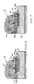
- the currently preferred embodiment of the invention is shown in cross-section in FIG. 2.
- the spring comprises a helical spring 42.
- a wire is wound to create the revolutions of the helical spring 42.
- the free inside diameter of the wound helical spring 42 is smaller than the diameter of the annular seat 36.
- the helical spring 42 is expanded and placed within the annular seat 36 of the valve body 22, and the spring 42 compresses and captures the fabric 34 between itself and the valve body 22, creating a controlled inwardly-directed radial force. While the spring 42 resiliently deforms about the valve body 22, it will be appreciated that the spring may deform both elastically and plastically. It will be appreciated, however, that it is the elastic deformation which primarily results in the torque-resisting radial force.
- the free diameter and number of revolutions of the helical spring 42 about the valve body 22 is dependent upon the thickness of the wire itself and the spring constant, thereof, the width of the annular seat 36, and the desired rotation-resisting torque.
- the adjacent revolutions of the helical spring 42 are relatively close to one another when wound about the valve body 22 and lie flat within the annular seat 36 once assembled.
- the helical spring 42 makes approximately 2 3 ⁇ 4 revolutions around the valve body 22. It will be appreciated, however, that the wire might be sized different and/or wound a different number of revolutions depending upon the specific geometry of the valve body and the characteristics desired.
- the wire of the helical spring 42 of the preferred embodiment of the invention has a substantially square cross-section.
- the adjacent coils of the helical spring 42 may be disposed such that they present a substantially smooth and continuous surface toward the fabric 34 of the cuff assembly 32. In this way, the inner surface of the helical spring 42 applies an inwardly-directed radial force on the fabric 34 and in turn on the valve body 22.
- the spring may be formed from a biocompatible material, which has long term corrosion resistance, and appropriate strength, rigidity, radiopacity, creep and fatigue characteristics.
- the currently preferred material is Elgiloy®, a cobalt-chrome-nickel alloy [ASTM F 1058].
- Other appropriate spring materials may include MP35N, nickel-titanium alloys, titanium and stainless steel.
- Other biocompatible materials, including polymers, are within the contemplation of the invention.
- a restraining ring element or assembly 44 may be provided.
- the restraining ring element comprises two individual restraining rings 46, 48.
- the restraining ring element 44 is disposed circumferentially about the spring 42 to constrain radial expansion of the spring 42. In this way, the restraining ring element 44 ensures that the coils of the spring 42 remain in the flat position shown in FIG. 2, preventing the coils from being pulled radially away from the annular seat and/or riding up over the shoulders.
- the restraining ring element 44 helps to retain the spring in the annular seat and minimizes the creation of a "gap" from occurring between the cuff assembly 32 and the valve body 22, as might happen, for example, when a lateral force is applied.
- the restraining ring element 44 is provided with flanges 46a, 48a which extend radially inward.
- the flanges 46a, 48a engage the lateral edges of the spring 42 to limit the lateral movement of the restraining ring element 44 relative to the spring 42 and the valve body 22.
- the restraining ring element 44 of the embodiment shown in FIG. 2 is preferably split and comprises two individual restraining rings 46, 48 that may be separately assembled onto the valve body 22.
- the restraining rings 46, 48 are identical, each having a flange 46a, 48a extending radially inwardly.
- the restraining ring element may comprise a single restraining ring (as will be described with regard to later embodiments), two restraining rings (as described with regard to the embodiment shown in FIG. 2), or, alternately, even three or more individual restraining rings.
- the restraining ring element 44 need not necessarily include two flanges.
- the restraining ring element 44 might comprise only one, or no laterally extending flanges.
- the restraining ring element 44 should be formed from a material which will not result in galvanic interaction when the valve assembly is implanted in the body.
- the restraining rings 46, 48 are manufactured from MP35N (ASTM F 562).
- ASTM F 562 ASTM F 562
- alternate materials such as titanium, Elgiloy®, and polymers such as Delrin® may be equally suitable, so long as they provide adequate strength, structural integrity, resistance to corrosion and are biocompatible. Other biocompatible materials and polymers are within the contemplation of the invention.
- the spring 42 compensates for component tolerance extremes. Torque control is influenced by the dimensions of the spring 42 and the fabric 34, and the external dimensions of the valve body 22. The resilience of the spring 42 compensates for some variances in the tolerances of these components such that the final resistance to torque demonstrated by valves 20 constructed in accordance with the invention is highly consistent. For example, in prototype evaluation, a large number of valves constructed according to the design shown in FIG. 2 had an average torque after sterilization of 38.4x10 -3 Nm (5.44 in-oz) with a standard deviation of 6x10 -3 Nm(0.85 in-oz.) based on an approximately normal distribution.
- FIG. 3 illustrates a preferred assembly fixture for use in assembling the rotatable cuff 32 according to the present invention to the heart valve 20. It will be appreciated, however, that any appropriate assembly device may be utilized.
- a base assembly 50 having two upstanding probes 50a, 50b is provided.
- the valve body 22, in which the leaflets 26a, 26b have been preassembled, is slid down onto the base assembly 50 with the pivot guards 22a, 22b facing downward.
- the probes 50a, 50b of the base assembly 50 extend upward through the valve body 22 and past the open leaflets 26a, 26b.
- a retainer slide 52 having outwardly extending flanges 52a, 52b is then inserted into the base assembly 50 through channels 50c, 50d.
- the retainer slide 52 is used as a receptacle for mandrel screw 55.
- a conically-shaped mandrel 54 is provided. Prior to assembling the mandrel 54 to the base assembly 50, the cuff fabric 34, one end of which has been folded over on itself and sewn to form a flange 34a, is slid down over the mandrel 54 until about 12.7mm (0.5 inch) of the cuff fabric 34 extends past the wide end of the mandrel 54. That portion of the cuff fabric 34 extending beyond the mandrel 54 is then tucked up inside a large bore 54a which opens to the bottom of the mandrel 54. In assembling aortic valves, as shown in FIGS. 1 and 2, the flanged end 34a of the cuff fabric 34 is tucked into the bore 54a, while with mitral valves, the opposite end 34b of the cuff fabric 34 is tucked into the bore 54a.
- the mandrel 54 to which the cuff fabric 34 has been assembled, is then slid down over the probes 50a, 50b of the base assembly 50, to which the valve body 22 and retainer slide 52 had been previously assembled.
- the mandrel 54 is securely seated on the base assembly 50 such that the cuff fabric 34 is pinched between the mandrel 54 and the valve body 22.
- a mandrel screw 55 is provided.
- the mandrel screw 55 comprises a conically shaped head 55a from which a threaded shaft 55b extends.
- the shaft 55b is inserted through a relatively small bore 54b extending through the mandrel 54, and into the retainer slide 52.
- the retainer slide 52 is provided with a threaded hole 52c which receives the end of the mandrel screw threaded shaft 55b.
- the mandrel screw 55 is then finger tightened into the hole 52c to provide a assembly.
- the cuff fabric 34 is then slid down the mandrel 54 and over the valve body 22, the cuff fabric 34 turning inside out as it is slid down.
- a driver 58 may be provided which may be slidably positioned over the mandrel 54 and mandrel screw conical head 55a.
- the driver 58 shown has a generally cylindrical shape with flexible fingers 58a which separate as the driver 58 slides down the mandrel 54.
- a rubber o-ring 58b is disposed about the fingers 58a.
- the driver 58 may be of any appropriate flexible, resilient material. Delrin® has been found to be a suitable material.
- the driver 58 may be used to push components down the mandrel and into position on the valve body 22, the fingers 58a spreading, but maintaining contact with both the mandrel 54 and the component as they slide along the surface of the mandrel 54.
- a first restraining ring 46 is positioned on the mandrel 54 with the flange 46a disposed downward.
- the driver 58 is then used to push the first restraining ring 46 down the mandrel 54 into the proper position on the valve body 22 over a layer of fabric 34 in the annular valve seat 36.
- the driver 58 may then be used to push the spring 42 into position, the spring 42 expanding as it slides down the mandrel 54 so that it may be seated in the annular seat 36.
- the driver 58 may then be used to push the second restraining ring 48 having the flange 48a disposed upward into the proper position.
- the assembler may then use his fingers or a soft tool to adjust the positions of the restraining rings 46, 48 to completely cover the spring 42.
- the mandrel screw may be loosened and removed, and the mandrel 54 lifted from the base assembly 50.
- the retainer slide 52 is then slid sideways from the probes 50a, 50b of the base assembly 50 so that the valve assembly may be removed.
- the cuff assembly 32 may then be sewn to form a toroidal shape.
- the valve 20 may then be sterilized by any accepted sterilization method; however, steam sterilization is currently used.
- the resilience of the spring additionally helps to minimize any change in torque resulting from relaxation of fibers in the sewing cuff fabric during the steam sterilization process.
- the spring includes a helical spring 66 that has a substantially round cross section.
- the helical spring 66 is oriented substantially coaxially with the annular valve seat 36.
- the helical spring 66 may be formed from a wire in a manner similar to that described with regard to the first embodiment of the invention, and may be similarly assembled.
- the ends of the helical spring 66 may be end-ground.
- the embodiment shown in FIG. 4 includes no restraining rings. It will be appreciated, however, that a two part ring element 70, 72 or a single ring element 74 may be provided, as in the embodiments illustrated in FIGS. 5 and 6, respectively.
- the restraining rings 70, 72, 74 preferably include radially extending flanges 70a and 72a, 74a and 74b, respectively.
- the restraining rings in these embodiments perform in substantially the same manner as described above with regard to FIG. 2. It will be appreciated, however, that the one piece ring element 74 shown in FIG. 6 may be assembled only after the spring 66 is properly positioned about the valve body 22.
- a thin foil strip 76 of biocompatible material such as Elgiloy®, Delrin®, or similar material is shown disposed between the helical spring and the fabric 34, within the annular seat 36.
- the foil strip 76 may be a continuous ring or a strip which is laid along the fabric 34 about the circumference of the annular seat 36.
- the coils of the spring 66 bear against the foil strip 76 such that the foil strip 76 distributes and transmits a substantially uniform inwardly-directed radial force to the seat 36.
- the foil strip 76 helps to prevent the ends of adjacent coils of the spring 66 from pulling away from the annular valve seat 36, and, therefore, minimizes the opportunity for the formation of a gap between the cuff assembly 32 and the valve body 22.
- heart valve prostheses constructed in accordance with the invention provide a predictable level of rotation resisting torque over a desired range.
- the present invention permits the resilience of the spring to compensate for relaxation of other components of the valve, such as the cuff fabric, which may occur during the sterilization processes and thereafter, and to minimize the change in torque as a result of that relaxation.
- the resilience of the spring compensates for some variations in the other components of the valve, such as minor manufacturing. variations in the orifice dimensions and differences in the thickness and other minor variations in the fabric. This reduces dependence on individual assembler skill and valve-to-valve consistency.
- the spring can be manufactured with well known technology to a predictable level of force, a target manufacturing range for desired torque levels may be established and maintained within design limits in the final product.
- the invention yields heart valve prostheses which employ well known technology to result in a valve which may be easily adjusted by the surgeon during implantation, yet resist spontaneous rotation after implantation.
- rotatable valve design may employ common or known fabric and valve bodies or orifices, as in the case of the referenced commercial valve embodying the valve disclosed in U.S. Patent 4,276,658, such that the size, configuration and appearance of the rotatable valve are very similar to the current design non-rotatable valve. This may minimize regulatory approval issues and permit established implantation procedures to be continued.
- the rotatable cuff design is also extremely compact and, in the case of the referenced commercial valve embodying the valve disclosed in U.S. Patent 4,276,658, it does not significantly increase the diameter of the sewing cuff over the heretofore standard, non-rotatable cuff design. As a result, the internal diameter of the orifice may be maintained at a maximum to ensure maximum blood flow once implanted.
- the rotatable heart valve is of a relatively simple design and may be readily and consistently assembled using a conically shaped assembly fixture. As a result, heart valves having the desired consistent torque-resisting characteristics may be economically manufactured in the volumes required.
- valve may be implanted using the most advanced surgical techniques. More specifically, the metal components of the rotatable cuff design are more reliable against cutting edge needles than is the case with existing cuffs secured to the valve with conventional sutures. After implantation, the orientation of the rotatable valve may according to the invention be verified by X-ray inasmuch as the ring elements and springs will increase the degree of radiopacity.
Landscapes
- Health & Medical Sciences (AREA)
- Engineering & Computer Science (AREA)
- Biomedical Technology (AREA)
- Cardiology (AREA)
- Oral & Maxillofacial Surgery (AREA)
- Transplantation (AREA)
- Heart & Thoracic Surgery (AREA)
- Vascular Medicine (AREA)
- Life Sciences & Earth Sciences (AREA)
- Animal Behavior & Ethology (AREA)
- General Health & Medical Sciences (AREA)
- Public Health (AREA)
- Veterinary Medicine (AREA)
- Prostheses (AREA)
Abstract
Description
Claims (6)
- A heart valve prosthesis comprising a generally annular orifice structure (22), at least one occluder (26a,26b) which moves between a first position to substantially block fluid flow through the orifice structure (22) in one direction and a second position to permit fluid flow through the orifice structure (22) in the direction opposite to the first direction and a rotatable sewing cuff assembly (32) for the generally annular orifice structure (22), wherein the sewing cuff assembly (32) has a resiliently deformed spring (42,66,80,90,92,94) which retains the sewing cuff assembly (32) on the orifice structure (22) and which providies and exerts a controlled inwardly directed radial force on a circumferential surface (36) of the orifice structure (22) to result in a rotation-resisting torque sufficient to resist rotation of the sewing cuff assembly (32) relative to the orifice structure (22) during normal operation of the valve after implantation but low enough to permit assisted rotation, and
characterised in that the spring is a helical spring oriented substantially coaxially with the circumferential surface of the orifice structure, the spring comprising at least one revolution, the free inside diameter of the helical spring being smaller than that assumed by the spring when in place over the circumferential surface, resulting in the provision and application of the controlled inwardly directed radial force to the circumferential surface. - A heart valve prosthesis as claimed in claim 1, characterised in that the spring exerts the radial force through at least one layer of fabric which is rotatable relative to the orifice structure.
- A heart valve prosthesis as claimed in any preceding claim, characterised in that the orifice structure further comprises opposed retaining shoulders on each side of the circumferential surface, the inside diameter of the spring being sized relative to the outside diameter of the shoulders such that, once the spring is assembled between the shoulders, the spring must undergo forced radial expansion to be moved out of alignment in the axial direction with the circumferential surface.
- A heart valve prosthesis as claimed in any one of the preceding claims, characterised in that the resiliently deformed spring provides a controlled axially directed force.
- A heart valve prosthesis as claimed in any one of the preceding claims characterised in that the sewing cuff assembly further comprises a ring element to circumferentially constrain the radial expansion of the spring about the entire circumference of the spring.
- A method of assembling a heart valve prosthesis as claimed in any one of claims 1 to 5, the method being characterised by providing a valve support structure (50) upon which the orifice structure (22) may be securely mounted, providing a conical guide and expansion member (54) over which elements (32,42,46,48) of the sewing cuff (32) may be slid, the largest end of the conical member (54) being positioned adjacent the orifice structure (22), the diameter of the member adjacent the orifice structure (22) being arranged to maintain the elements (32,42,46,48) of the sewing cuff (32) at diameters which allow the elements (32,42,46,48) to pass onto the largest outside diameter of the orifice structure (22) without further expansion, providing a driver (58) having a plurality of resilient circumferentially disposed fingers (58a), the ends of which form an annular surface which are arranged to abut the elements (32,42,46,48) of the sewing cuff (32), and advancing the elements (32,42,46,48) of the sewing cuff (32) along the conical member (54) and onto the orifice structure (22) by means of the driver (58), the fingers (58a) expanding circumferentially as the elements (32,42,46,48) are pushed toward the orifice structure (22).
Applications Claiming Priority (3)
| Application Number | Priority Date | Filing Date | Title |
|---|---|---|---|
| US32716494A | 1994-10-21 | 1994-10-21 | |
| US327164 | 1994-10-21 | ||
| PCT/US1995/013261 WO1996012452A1 (en) | 1994-10-21 | 1995-10-20 | Rotatable sewing cuff for a heart valve prosthesis |
Related Child Applications (1)
| Application Number | Title | Priority Date | Filing Date |
|---|---|---|---|
| EP01203794 Division | 2001-10-08 |
Publications (2)
| Publication Number | Publication Date |
|---|---|
| EP0786976A1 EP0786976A1 (en) | 1997-08-06 |
| EP0786976B1 true EP0786976B1 (en) | 2002-08-07 |
Family
ID=23275435
Family Applications (1)
| Application Number | Title | Priority Date | Filing Date |
|---|---|---|---|
| EP95938758A Expired - Lifetime EP0786976B1 (en) | 1994-10-21 | 1995-10-20 | Heart valve prosthesis |
Country Status (14)
| Country | Link |
|---|---|
| US (1) | US5876436A (en) |
| EP (1) | EP0786976B1 (en) |
| JP (1) | JP3512421B2 (en) |
| CN (1) | CN1150864C (en) |
| AT (1) | ATE221758T1 (en) |
| AU (1) | AU4001695A (en) |
| BR (1) | BR9509388A (en) |
| CA (1) | CA2203245C (en) |
| DE (1) | DE69527722T2 (en) |
| ES (1) | ES2176345T3 (en) |
| IL (1) | IL115680A (en) |
| RU (1) | RU2158565C2 (en) |
| WO (1) | WO1996012452A1 (en) |
| ZA (1) | ZA958860B (en) |
Families Citing this family (92)
| Publication number | Priority date | Publication date | Assignee | Title |
|---|---|---|---|---|
| WO1996040010A1 (en) * | 1995-06-07 | 1996-12-19 | St. Jude Medical, Inc. | Prosthetic heart valve with increased lumen |
| US6402780B2 (en) | 1996-02-23 | 2002-06-11 | Cardiovascular Technologies, L.L.C. | Means and method of replacing a heart valve in a minimally invasive manner |
| US5755783A (en) * | 1996-07-29 | 1998-05-26 | Stobie; Robert | Suture rings for rotatable artificial heart valves |
| US6050936A (en) * | 1997-01-02 | 2000-04-18 | Myocor, Inc. | Heart wall tension reduction apparatus |
| US7883539B2 (en) | 1997-01-02 | 2011-02-08 | Edwards Lifesciences Llc | Heart wall tension reduction apparatus and method |
| US6183411B1 (en) | 1998-09-21 | 2001-02-06 | Myocor, Inc. | External stress reduction device and method |
| US6406420B1 (en) * | 1997-01-02 | 2002-06-18 | Myocor, Inc. | Methods and devices for improving cardiac function in hearts |
| US6332893B1 (en) | 1997-12-17 | 2001-12-25 | Myocor, Inc. | Valve to myocardium tension members device and method |
| US6074418A (en) | 1998-04-20 | 2000-06-13 | St. Jude Medical, Inc. | Driver tool for heart valve prosthesis fasteners |
| US6176877B1 (en) * | 1998-04-20 | 2001-01-23 | St. Jude Medical, Inc. | Two piece prosthetic heart valve |
| US6260552B1 (en) * | 1998-07-29 | 2001-07-17 | Myocor, Inc. | Transventricular implant tools and devices |
| US6309417B1 (en) | 1999-05-12 | 2001-10-30 | Paul A. Spence | Heart valve and apparatus for replacement thereof |
| US6358278B1 (en) * | 1999-09-24 | 2002-03-19 | St. Jude Medical, Inc. | Heart valve prosthesis with rotatable cuff |
| US6537198B1 (en) * | 2000-03-21 | 2003-03-25 | Myocor, Inc. | Splint assembly for improving cardiac function in hearts, and method for implanting the splint assembly |
| US6468305B1 (en) | 2000-05-16 | 2002-10-22 | St. Jude Medical, Inc. | Two piece valve |
| US7083644B1 (en) * | 2000-05-24 | 2006-08-01 | Scimed Life Systems, Inc. | Implantable prostheses with improved mechanical and chemical properties |
| US8366769B2 (en) | 2000-06-01 | 2013-02-05 | Edwards Lifesciences Corporation | Low-profile, pivotable heart valve sewing ring |
| US7077861B2 (en) * | 2000-07-06 | 2006-07-18 | Medtentia Ab | Annuloplasty instrument |
| US6419696B1 (en) * | 2000-07-06 | 2002-07-16 | Paul A. Spence | Annuloplasty devices and related heart valve repair methods |
| WO2002019951A1 (en) | 2000-09-07 | 2002-03-14 | Viacor, Inc. | Fixation band for affixing a prosthetic heart valve to tissue |
| US6616684B1 (en) * | 2000-10-06 | 2003-09-09 | Myocor, Inc. | Endovascular splinting devices and methods |
| US6723038B1 (en) | 2000-10-06 | 2004-04-20 | Myocor, Inc. | Methods and devices for improving mitral valve function |
| US6506197B1 (en) | 2000-11-15 | 2003-01-14 | Ethicon, Inc. | Surgical method for affixing a valve to a heart using a looped suture combination |
| US6716244B2 (en) | 2000-12-20 | 2004-04-06 | Carbomedics, Inc. | Sewing cuff assembly for heart valves |
| DK1423066T3 (en) | 2001-09-07 | 2008-11-17 | Mardil Inc | Method and apparatus for external cardiac stabilization |
| US7097659B2 (en) | 2001-09-07 | 2006-08-29 | Medtronic, Inc. | Fixation band for affixing a prosthetic heart valve to tissue |
| EP1453424B1 (en) * | 2001-12-13 | 2006-06-07 | Oneg Hakarmel | Device for excluding blood out of a limb |
| US7201771B2 (en) * | 2001-12-27 | 2007-04-10 | Arbor Surgical Technologies, Inc. | Bioprosthetic heart valve |
| US6764510B2 (en) | 2002-01-09 | 2004-07-20 | Myocor, Inc. | Devices and methods for heart valve treatment |
| US7959674B2 (en) * | 2002-07-16 | 2011-06-14 | Medtronic, Inc. | Suture locking assembly and method of use |
| US7172625B2 (en) * | 2002-07-16 | 2007-02-06 | Medtronic, Inc. | Suturing rings for implantable heart valve prostheses |
| US7578843B2 (en) | 2002-07-16 | 2009-08-25 | Medtronic, Inc. | Heart valve prosthesis |
| US7112219B2 (en) * | 2002-11-12 | 2006-09-26 | Myocor, Inc. | Devices and methods for heart valve treatment |
| US7247134B2 (en) * | 2002-11-12 | 2007-07-24 | Myocor, Inc. | Devices and methods for heart valve treatment |
| US8551162B2 (en) | 2002-12-20 | 2013-10-08 | Medtronic, Inc. | Biologically implantable prosthesis |
| US8021421B2 (en) | 2003-08-22 | 2011-09-20 | Medtronic, Inc. | Prosthesis heart valve fixturing device |
| US7556647B2 (en) * | 2003-10-08 | 2009-07-07 | Arbor Surgical Technologies, Inc. | Attachment device and methods of using the same |
| ITTO20040135A1 (en) | 2004-03-03 | 2004-06-03 | Sorin Biomedica Cardio Spa | CARDIAC VALVE PROSTHESIS |
| US20050222675A1 (en) * | 2004-04-06 | 2005-10-06 | Sauter Joseph A | Implantable prosthetic heart valve comprising a valve body and a tubular vascular graft |
| US7641687B2 (en) * | 2004-11-02 | 2010-01-05 | Carbomedics Inc. | Attachment of a sewing cuff to a heart valve |
| ITTO20050074A1 (en) | 2005-02-10 | 2006-08-11 | Sorin Biomedica Cardio Srl | CARDIAC VALVE PROSTHESIS |
| US7513909B2 (en) * | 2005-04-08 | 2009-04-07 | Arbor Surgical Technologies, Inc. | Two-piece prosthetic valves with snap-in connection and methods for use |
| US20060247491A1 (en) * | 2005-04-27 | 2006-11-02 | Vidlund Robert M | Devices and methods for heart valve treatment |
| US8211169B2 (en) | 2005-05-27 | 2012-07-03 | Medtronic, Inc. | Gasket with collar for prosthetic heart valves and methods for using them |
| CN102028565B (en) * | 2005-07-13 | 2012-07-18 | 爱德华兹生命科学公司 | Prosthetic mitral heart valve having a contoured sewing ring |
| US7682391B2 (en) * | 2005-07-13 | 2010-03-23 | Edwards Lifesciences Corporation | Methods of implanting a prosthetic mitral heart valve having a contoured sewing ring |
| US7967857B2 (en) | 2006-01-27 | 2011-06-28 | Medtronic, Inc. | Gasket with spring collar for prosthetic heart valves and methods for making and using them |
| JP5102279B2 (en) * | 2006-03-10 | 2012-12-19 | メドトロニック,インコーポレイテッド | Artificial valve introducer, method for producing the same and method for using the same |
| EP2023860A2 (en) | 2006-04-29 | 2009-02-18 | Arbor Surgical Technologies, Inc. | Multiple component prosthetic heart valve assemblies and apparatus and methods for delivering them |
| FR2902344B1 (en) * | 2006-06-15 | 2008-09-05 | Carpentier Matra Carmat | CONNECTING DEVICE BETWEEN HEART PROSTHESIS AND NATURAL HEADS |
| CA2664557C (en) | 2006-11-07 | 2015-05-26 | Corvia Medical, Inc. | Devices and methods for the treatment of heart failure |
| US9232997B2 (en) | 2006-11-07 | 2016-01-12 | Corvia Medical, Inc. | Devices and methods for retrievable intra-atrial implants |
| US20110257723A1 (en) | 2006-11-07 | 2011-10-20 | Dc Devices, Inc. | Devices and methods for coronary sinus pressure relief |
| US8460372B2 (en) | 2006-11-07 | 2013-06-11 | Dc Devices, Inc. | Prosthesis for reducing intra-cardiac pressure having an embolic filter |
| US10413284B2 (en) | 2006-11-07 | 2019-09-17 | Corvia Medical, Inc. | Atrial pressure regulation with control, sensing, monitoring and therapy delivery |
| RU2350300C1 (en) * | 2007-07-19 | 2009-03-27 | Закрытое Акционерное Общество Научно-Производственное Предприятие "Мединж" | Heart valve prosthesis (versions) |
| US9848981B2 (en) | 2007-10-12 | 2017-12-26 | Mayo Foundation For Medical Education And Research | Expandable valve prosthesis with sealing mechanism |
| US9131944B2 (en) * | 2008-01-29 | 2015-09-15 | Ohk Medical Devices Ltd. | Mobile torus devices |
| US8366739B2 (en) * | 2008-01-30 | 2013-02-05 | Ohk Medical Devices Ltd. | Motion control devices |
| US20090209891A1 (en) * | 2008-02-14 | 2009-08-20 | Ohk Medical Devices Ltd. | Pressure controlling devices |
| ATE554731T1 (en) * | 2008-05-16 | 2012-05-15 | Sorin Biomedica Cardio Srl | ATRAAUMATIC PROSTHETIC HEART VALVE PROSTHESIS |
| US9375310B2 (en) * | 2012-12-31 | 2016-06-28 | Edwards Lifesciences Corporation | Surgical heart valves adapted for post-implant expansion |
| WO2010051025A1 (en) | 2008-10-30 | 2010-05-06 | St. Jude Medical, Inc. | Collapsible/expandable prosthetic heart valve delivery system and methods |
| US8905961B2 (en) * | 2008-12-19 | 2014-12-09 | St. Jude Medical, Inc. | Systems, apparatuses, and methods for cardiovascular conduits and connectors |
| ES2551694T3 (en) | 2008-12-23 | 2015-11-23 | Sorin Group Italia S.R.L. | Expandable prosthetic valve with anchoring appendages |
| CN101601611B (en) * | 2009-04-03 | 2012-02-01 | 中国人民解放军第二军医大学 | Assembled artificial heart biological valve treatment device for repeated replacement under minimally invasive surgery |
| EP2628465A1 (en) | 2009-04-27 | 2013-08-21 | Sorin Group Italia S.r.l. | Prosthetic vascular conduit |
| CA2778129C (en) * | 2009-04-28 | 2014-09-02 | Dc Devices, Inc. | Devices, systems and methods to treat heart failure |
| US9757107B2 (en) | 2009-09-04 | 2017-09-12 | Corvia Medical, Inc. | Methods and devices for intra-atrial shunts having adjustable sizes |
| US8808369B2 (en) | 2009-10-05 | 2014-08-19 | Mayo Foundation For Medical Education And Research | Minimally invasive aortic valve replacement |
| US8449608B2 (en) * | 2010-01-22 | 2013-05-28 | Edwards Lifesciences Corporation | Tricuspid ring |
| WO2011094521A2 (en) | 2010-01-29 | 2011-08-04 | Dc Devices, Inc. | Devices and methods for reducing venous pressure |
| WO2011093941A2 (en) | 2010-01-29 | 2011-08-04 | Dc Devices, Inc. | Devices and systems for treating heart failure |
| IT1400327B1 (en) | 2010-05-21 | 2013-05-24 | Sorin Biomedica Cardio Srl | SUPPORT DEVICE FOR VALVULAR PROSTHESIS AND CORRESPONDING CORRESPONDENT. |
| AU2011292463B2 (en) | 2010-08-17 | 2014-01-23 | St. Jude Medical, Inc. | Tip for medical implant delivery system |
| US12303119B2 (en) | 2011-02-10 | 2025-05-20 | Corvia Medical, Inc. | Apparatus and methods to create and maintain an intra-atrial pressure relief opening |
| JP2014512869A (en) | 2011-02-10 | 2014-05-29 | ディーシー ディヴァイシーズ インコーポレイテッド | Apparatus and method for forming and maintaining an intraatrial pressure relief opening |
| ES2641902T3 (en) | 2011-02-14 | 2017-11-14 | Sorin Group Italia S.R.L. | Sutureless anchoring device for cardiac valve prostheses |
| EP2486894B1 (en) | 2011-02-14 | 2021-06-09 | Sorin Group Italia S.r.l. | Sutureless anchoring device for cardiac valve prostheses |
| US9205236B2 (en) | 2011-12-22 | 2015-12-08 | Corvia Medical, Inc. | Methods, systems, and devices for resizable intra-atrial shunts |
| EP2609893B1 (en) | 2011-12-29 | 2014-09-03 | Sorin Group Italia S.r.l. | A kit for implanting prosthetic vascular conduits |
| US9005155B2 (en) | 2012-02-03 | 2015-04-14 | Dc Devices, Inc. | Devices and methods for treating heart failure |
| US10588611B2 (en) | 2012-04-19 | 2020-03-17 | Corvia Medical Inc. | Implant retention attachment and method of use |
| US9649480B2 (en) | 2012-07-06 | 2017-05-16 | Corvia Medical, Inc. | Devices and methods of treating or ameliorating diastolic heart failure through pulmonary valve intervention |
| US9775636B2 (en) | 2013-03-12 | 2017-10-03 | Corvia Medical, Inc. | Devices, systems, and methods for treating heart failure |
| CN103690272B (en) * | 2014-01-15 | 2016-08-17 | 梁宏亮 | Expanding petal skirt aorta mechanical valve prosthesis |
| US10675450B2 (en) | 2014-03-12 | 2020-06-09 | Corvia Medical, Inc. | Devices and methods for treating heart failure |
| JP6799526B2 (en) | 2014-07-23 | 2020-12-16 | コルヴィア メディカル インコーポレイテッド | Equipment and methods for the treatment of heart failure |
| ITUB20152409A1 (en) | 2015-07-22 | 2017-01-22 | Sorin Group Italia Srl | VALVE SLEEVE FOR VALVULAR PROSTHESIS AND CORRESPONDING DEVICE |
| CN107789095B (en) * | 2016-08-29 | 2021-04-02 | 先健科技(深圳)有限公司 | Preparation method of annuloplasty ring |
| US12318289B2 (en) | 2018-05-23 | 2025-06-03 | Corcym S.R.L. | Device for the in-situ delivery of heart valve prosthesis |
| WO2019224577A1 (en) | 2018-05-23 | 2019-11-28 | Sorin Group Italia S.R.L. | A cardiac valve prosthesis |
Citations (1)
| Publication number | Priority date | Publication date | Assignee | Title |
|---|---|---|---|---|
| US5035709A (en) * | 1990-03-29 | 1991-07-30 | Baxter International Inc. | Mechanical heart valve with compliant sewing ring |
Family Cites Families (61)
| Publication number | Priority date | Publication date | Assignee | Title |
|---|---|---|---|---|
| US3099016A (en) * | 1960-08-11 | 1963-07-30 | Edwards Miles Lowell | Heart valve |
| US3143742A (en) * | 1963-03-19 | 1964-08-11 | Surgitool Inc | Prosthetic sutureless heart valve |
| GB1127325A (en) * | 1965-08-23 | 1968-09-18 | Henry Berry | Improved instrument for inserting artificial heart valves |
| US3491376A (en) | 1965-10-06 | 1970-01-27 | Donald P Shiley | Heart valve with separate suturing ring sub-assembly |
| US3579642A (en) * | 1968-04-15 | 1971-05-25 | Bart T Heffernan | Heart valve assembly and method of implanting in the body |
| US3727240A (en) * | 1969-04-21 | 1973-04-17 | Medical Inc | Suturing member for implantable devices such as heart valves |
| US3628535A (en) * | 1969-11-12 | 1971-12-21 | Nibot Corp | Surgical instrument for implanting a prosthetic heart valve or the like |
| US3725961A (en) * | 1970-12-29 | 1973-04-10 | Baxter Laboratories Inc | Prosthetic heart valve having fabric suturing element |
| US3691567A (en) * | 1971-05-07 | 1972-09-19 | Baxter Laboratories Inc | Prosthetic heart valve having a pair of support rings of dissimilar material |
| US3763548A (en) * | 1972-03-17 | 1973-10-09 | L Anderson | Method of mounting a rotatable suturing member on a device |
| US3959827A (en) * | 1972-08-08 | 1976-06-01 | Kaster Robert L | Heart valve prosthesis |
| US3825957A (en) * | 1972-08-08 | 1974-07-30 | R Kaster | Pivoting disc heart valve with rod guide |
| US3859668A (en) * | 1972-08-11 | 1975-01-14 | Medical Inc | Rotatable suturing member |
| US3781969A (en) * | 1972-08-11 | 1974-01-01 | Medical Inc | Method of forming rotatable suturing member on a device |
| US3828787A (en) * | 1972-09-08 | 1974-08-13 | Medical Inc | Collet for holding heart valve |
| US3800403A (en) * | 1972-10-10 | 1974-04-02 | Medical Inc | Method of making a suturing member and mounting the suturing member on a device |
| US3839741A (en) * | 1972-11-17 | 1974-10-08 | J Haller | Heart valve and retaining means therefor |
| US3996623A (en) * | 1974-07-30 | 1976-12-14 | Kaster Robert L | Method of implanting a prosthetic device and suturing member therefor |
| US4078268A (en) * | 1975-04-24 | 1978-03-14 | St. Jude Medical, Inc. | Heart valve prosthesis |
| US3997923A (en) * | 1975-04-28 | 1976-12-21 | St. Jude Medical, Inc. | Heart valve prosthesis and suturing assembly and method of implanting a heart valve prosthesis in a heart |
| US4276658A (en) * | 1977-11-02 | 1981-07-07 | St. Jude Medical, Inc. | Heart valve prosthesis |
| US4197593A (en) * | 1978-03-03 | 1980-04-15 | Kastec Corporation | Rotatably positionable heart valve and method |
| US4233690A (en) * | 1978-05-19 | 1980-11-18 | Carbomedics, Inc. | Prosthetic device couplings |
| US4240161A (en) * | 1979-02-21 | 1980-12-23 | Medical, Incorporated | Arcuate disc heart valve |
| USRE30507E (en) * | 1979-03-22 | 1981-02-10 | Heart valve prosthesis | |
| US4328592A (en) * | 1979-08-07 | 1982-05-11 | Hemex, Inc. | Heart valve prosthesis |
| US4865600A (en) * | 1981-08-25 | 1989-09-12 | Baxter International Inc. | Mitral valve holder |
| US4599081A (en) * | 1982-09-30 | 1986-07-08 | Cohen Fred M | Artificial heart valve |
| US4680031A (en) * | 1982-11-29 | 1987-07-14 | Tascon Medical Technology Corporation | Heart valve prosthesis |
| US4535483A (en) * | 1983-01-17 | 1985-08-20 | Hemex, Inc. | Suture rings for heart valves |
| AR229309A1 (en) * | 1983-04-20 | 1983-07-15 | Barone Hector Daniel | MOUNT FOR CARDIAC VALVES |
| US4665906A (en) | 1983-10-14 | 1987-05-19 | Raychem Corporation | Medical devices incorporating sim alloy elements |
| US4890944A (en) * | 1983-12-27 | 1990-01-02 | Bristol-Myers Company | Container and delivery system for stick compositions |
| IT1208326B (en) * | 1984-03-16 | 1989-06-12 | Sorin Biomedica Spa | CARDIAC VALVE PROSTHESIS PROVIDED WITH VALVES OF ORGANIC FABRIC |
| US4655462A (en) * | 1985-01-07 | 1987-04-07 | Peter J. Balsells | Canted coiled spring and seal |
| DE3507109A1 (en) * | 1985-03-01 | 1986-09-04 | Naučno-issledovatel'skij institut chirurgii imeni A.V. Višnevskogo Akademii medicinskich nauk SSSR, Moskau/Moskva | HEART VALVE PROSTHESIS |
| US4683883A (en) * | 1985-04-30 | 1987-08-04 | Hemex Scientific, Inc. | Two-piece heart valve holder/rotator |
| US4863460A (en) * | 1986-03-04 | 1989-09-05 | Sta-Set Corporation | Suture rings for heart valves |
| US4743253A (en) * | 1986-03-04 | 1988-05-10 | Magladry Ross E | Suture rings for heart valves and method of securing same to heart valves |
| US4790843A (en) * | 1986-06-16 | 1988-12-13 | Baxter Travenol Laboratories, Inc. | Prosthetic heart valve assembly |
| US4826144A (en) * | 1988-04-25 | 1989-05-02 | Peter J. Balsells | Inside back angle canted coil spring |
| US5117066A (en) * | 1988-04-25 | 1992-05-26 | Peter J. Balsells | Retaining and locking electromagnetic gasket |
| US5108078A (en) * | 1988-04-25 | 1992-04-28 | Peter J. Balsells | Canted-coil spring loaded while in a cavity |
| US4915366A (en) * | 1988-04-25 | 1990-04-10 | Peter J. Balsells | Outside back angle canted coil spring |
| US4876781A (en) * | 1988-04-25 | 1989-10-31 | Peter J. Balsells | Method of making a garter-type axially resilient coiled spring |
| US5079388A (en) * | 1989-12-01 | 1992-01-07 | Peter J. Balsells | Gasket for sealing electromagnetic waves |
| US5072070A (en) * | 1989-12-01 | 1991-12-10 | Peter J. Balsells | Device for sealing electromagnetic waves |
| JPH0347246A (en) * | 1989-04-13 | 1991-02-28 | Olympus Optical Co Ltd | Treating tool for endoscope |
| IT1240110B (en) * | 1990-02-21 | 1993-11-27 | Sorin Biomedica Spa | CARDIAC VALVE PROSTHESIS |
| RU1767723C (en) * | 1990-08-14 | 1995-01-27 | Кирово-Чепецкий химический комбинат | Artificial heart valve |
| US5071431A (en) * | 1990-11-07 | 1991-12-10 | Carbomedics, Inc. | Suture rings for heart valves and method of securing suture rings to heart valves |
| US5163955A (en) * | 1991-01-24 | 1992-11-17 | Autogenics | Rapid assembly, concentric mating stent, tissue heart valve with enhanced clamping and tissue alignment |
| US5354330A (en) * | 1991-10-31 | 1994-10-11 | Ats Medical Inc. | Heart valve prosthesis |
| US5178633A (en) * | 1992-04-21 | 1993-01-12 | Carbon Implants Inc. | Suture ring for heart valve prosthesis |
| US5236450A (en) * | 1992-06-04 | 1993-08-17 | Carbon Implants, Inc. | Heart valve holder-rotator |
| US5403305A (en) * | 1993-04-08 | 1995-04-04 | Carbomedics, Inc. | Mitral valve prosthesis rotator |
| AU1301095A (en) * | 1993-12-13 | 1995-07-03 | Brigham And Women's Hospital | Aortic valve supporting device |
| US5443502A (en) * | 1994-06-02 | 1995-08-22 | Carbomedics, Inc. | Rotatable heart valve holder |
| US5480425A (en) * | 1994-06-09 | 1996-01-02 | Carbomedics, Inc. | Integrated heart valve rotator and holder |
| US5582607A (en) * | 1994-09-09 | 1996-12-10 | Carbomedics, Inc. | Heart valve prosthesis rotator with bendable shaft and drive mechanism |
| US5607470A (en) * | 1995-05-01 | 1997-03-04 | Milo; Simcha | Suture rings for prosthetic heart valves |
-
1995
- 1995-10-19 ZA ZA958860A patent/ZA958860B/en unknown
- 1995-10-19 IL IL11568095A patent/IL115680A/en not_active IP Right Cessation
- 1995-10-20 EP EP95938758A patent/EP0786976B1/en not_active Expired - Lifetime
- 1995-10-20 CA CA002203245A patent/CA2203245C/en not_active Expired - Fee Related
- 1995-10-20 DE DE69527722T patent/DE69527722T2/en not_active Expired - Lifetime
- 1995-10-20 ES ES95938758T patent/ES2176345T3/en not_active Expired - Lifetime
- 1995-10-20 RU RU97108068/14A patent/RU2158565C2/en active
- 1995-10-20 CN CNB951957848A patent/CN1150864C/en not_active Expired - Fee Related
- 1995-10-20 AT AT95938758T patent/ATE221758T1/en not_active IP Right Cessation
- 1995-10-20 WO PCT/US1995/013261 patent/WO1996012452A1/en not_active Ceased
- 1995-10-20 BR BR9509388A patent/BR9509388A/en not_active IP Right Cessation
- 1995-10-20 AU AU40016/95A patent/AU4001695A/en not_active Abandoned
- 1995-10-20 JP JP51401796A patent/JP3512421B2/en not_active Expired - Lifetime
-
1997
- 1997-02-13 US US08/799,289 patent/US5876436A/en not_active Expired - Lifetime
Patent Citations (1)
| Publication number | Priority date | Publication date | Assignee | Title |
|---|---|---|---|---|
| US5035709A (en) * | 1990-03-29 | 1991-07-30 | Baxter International Inc. | Mechanical heart valve with compliant sewing ring |
Also Published As
| Publication number | Publication date |
|---|---|
| RU2158565C2 (en) | 2000-11-10 |
| CN1150864C (en) | 2004-05-26 |
| MX9702880A (en) | 1997-10-31 |
| DE69527722T2 (en) | 2002-11-28 |
| DE69527722D1 (en) | 2002-09-12 |
| ES2176345T3 (en) | 2002-12-01 |
| CN1161644A (en) | 1997-10-08 |
| AU4001695A (en) | 1996-05-15 |
| ATE221758T1 (en) | 2002-08-15 |
| BR9509388A (en) | 1997-09-16 |
| CA2203245A1 (en) | 1996-05-02 |
| ZA958860B (en) | 1997-04-18 |
| WO1996012452A1 (en) | 1996-05-02 |
| CA2203245C (en) | 2003-09-02 |
| JP3512421B2 (en) | 2004-03-29 |
| IL115680A (en) | 1999-03-12 |
| US5876436A (en) | 1999-03-02 |
| IL115680A0 (en) | 1996-01-19 |
| JPH10507665A (en) | 1998-07-28 |
| EP0786976A1 (en) | 1997-08-06 |
Similar Documents
| Publication | Publication Date | Title |
|---|---|---|
| US5876436A (en) | Rotatable cuff assembly for a heart valve prosthesis | |
| EP1214022B1 (en) | Heart valve prosthesis with rotatable cuff | |
| US10595991B2 (en) | Heart valve assemblies | |
| EP1659981B1 (en) | Prosthesis fixturing device | |
| US5178633A (en) | Suture ring for heart valve prosthesis | |
| US5843179A (en) | Suture guard for prosthetic heart valve | |
| US6391053B1 (en) | Prosthetic heart valve with increased valve lumen | |
| US6786925B1 (en) | Driver tool with multiple drive gear layers for heart prosthesis fasteners | |
| US6425902B1 (en) | Surgical instrument for heart valve reconstruction | |
| JP2004512080A (en) | Driver tool with multiple drive gear layers for cardiac prosthesis fasteners | |
| MXPA97002880A (en) | Girable suturable ring for a cardiac valve protesis | |
| CA3101687A1 (en) | Circumferentially constrictive annuloplasty ring |
Legal Events
| Date | Code | Title | Description |
|---|---|---|---|
| PUAI | Public reference made under article 153(3) epc to a published international application that has entered the european phase |
Free format text: ORIGINAL CODE: 0009012 |
|
| 17P | Request for examination filed |
Effective date: 19970411 |
|
| AK | Designated contracting states |
Kind code of ref document: A1 Designated state(s): AT BE CH DE DK ES FR GB IE IT LI NL PT SE |
|
| 17Q | First examination report despatched |
Effective date: 20000713 |
|
| GRAG | Despatch of communication of intention to grant |
Free format text: ORIGINAL CODE: EPIDOS AGRA |
|
| RTI1 | Title (correction) |
Free format text: HEART VALVE PROSTHESIS |
|
| GRAG | Despatch of communication of intention to grant |
Free format text: ORIGINAL CODE: EPIDOS AGRA |
|
| GRAH | Despatch of communication of intention to grant a patent |
Free format text: ORIGINAL CODE: EPIDOS IGRA |
|
| GRAH | Despatch of communication of intention to grant a patent |
Free format text: ORIGINAL CODE: EPIDOS IGRA |
|
| GRAA | (expected) grant |
Free format text: ORIGINAL CODE: 0009210 |
|
| AK | Designated contracting states |
Kind code of ref document: B1 Designated state(s): AT BE CH DE DK ES FR GB IE IT LI NL PT SE |
|
| PG25 | Lapsed in a contracting state [announced via postgrant information from national office to epo] |
Ref country code: BE Free format text: LAPSE BECAUSE OF FAILURE TO SUBMIT A TRANSLATION OF THE DESCRIPTION OR TO PAY THE FEE WITHIN THE PRESCRIBED TIME-LIMIT Effective date: 20020807 Ref country code: AT Free format text: LAPSE BECAUSE OF FAILURE TO SUBMIT A TRANSLATION OF THE DESCRIPTION OR TO PAY THE FEE WITHIN THE PRESCRIBED TIME-LIMIT Effective date: 20020807 |
|
| REF | Corresponds to: |
Ref document number: 221758 Country of ref document: AT Date of ref document: 20020815 Kind code of ref document: T |
|
| REG | Reference to a national code |
Ref country code: GB Ref legal event code: FG4D |
|
| REG | Reference to a national code |
Ref country code: CH Ref legal event code: EP |
|
| REG | Reference to a national code |
Ref country code: IE Ref legal event code: FG4D |
|
| REF | Corresponds to: |
Ref document number: 69527722 Country of ref document: DE Date of ref document: 20020912 |
|
| PGFP | Annual fee paid to national office [announced via postgrant information from national office to epo] |
Ref country code: SE Payment date: 20021031 Year of fee payment: 8 |
|
| PG25 | Lapsed in a contracting state [announced via postgrant information from national office to epo] |
Ref country code: SE Free format text: LAPSE BECAUSE OF FAILURE TO SUBMIT A TRANSLATION OF THE DESCRIPTION OR TO PAY THE FEE WITHIN THE PRESCRIBED TIME-LIMIT Effective date: 20021107 Ref country code: DK Free format text: LAPSE BECAUSE OF FAILURE TO SUBMIT A TRANSLATION OF THE DESCRIPTION OR TO PAY THE FEE WITHIN THE PRESCRIBED TIME-LIMIT Effective date: 20021107 |
|
| PG25 | Lapsed in a contracting state [announced via postgrant information from national office to epo] |
Ref country code: PT Free format text: LAPSE BECAUSE OF FAILURE TO SUBMIT A TRANSLATION OF THE DESCRIPTION OR TO PAY THE FEE WITHIN THE PRESCRIBED TIME-LIMIT Effective date: 20021122 |
|
| REG | Reference to a national code |
Ref country code: ES Ref legal event code: FG2A Ref document number: 2176345 Country of ref document: ES Kind code of ref document: T3 |
|
| ET | Fr: translation filed | ||
| REG | Reference to a national code |
Ref country code: CH Ref legal event code: NV Representative=s name: PATENTANWAELTE FELDMANN & PARTNER AG |
|
| PLBE | No opposition filed within time limit |
Free format text: ORIGINAL CODE: 0009261 |
|
| STAA | Information on the status of an ep patent application or granted ep patent |
Free format text: STATUS: NO OPPOSITION FILED WITHIN TIME LIMIT |
|
| 26N | No opposition filed |
Effective date: 20030508 |
|
| PGFP | Annual fee paid to national office [announced via postgrant information from national office to epo] |
Ref country code: DE Payment date: 20131029 Year of fee payment: 19 Ref country code: GB Payment date: 20131028 Year of fee payment: 19 Ref country code: FR Payment date: 20131017 Year of fee payment: 19 Ref country code: IE Payment date: 20131025 Year of fee payment: 19 Ref country code: CH Payment date: 20131029 Year of fee payment: 19 |
|
| PGFP | Annual fee paid to national office [announced via postgrant information from national office to epo] |
Ref country code: IT Payment date: 20131024 Year of fee payment: 19 Ref country code: ES Payment date: 20131028 Year of fee payment: 19 Ref country code: NL Payment date: 20131026 Year of fee payment: 19 |
|
| REG | Reference to a national code |
Ref country code: DE Ref legal event code: R119 Ref document number: 69527722 Country of ref document: DE |
|
| REG | Reference to a national code |
Ref country code: NL Ref legal event code: V1 Effective date: 20150501 |
|
| REG | Reference to a national code |
Ref country code: CH Ref legal event code: PL |
|
| GBPC | Gb: european patent ceased through non-payment of renewal fee |
Effective date: 20141020 |
|
| REG | Reference to a national code |
Ref country code: IE Ref legal event code: MM4A |
|
| PG25 | Lapsed in a contracting state [announced via postgrant information from national office to epo] |
Ref country code: CH Free format text: LAPSE BECAUSE OF NON-PAYMENT OF DUE FEES Effective date: 20141031 Ref country code: LI Free format text: LAPSE BECAUSE OF NON-PAYMENT OF DUE FEES Effective date: 20141031 Ref country code: DE Free format text: LAPSE BECAUSE OF NON-PAYMENT OF DUE FEES Effective date: 20150501 Ref country code: GB Free format text: LAPSE BECAUSE OF NON-PAYMENT OF DUE FEES Effective date: 20141020 |
|
| REG | Reference to a national code |
Ref country code: FR Ref legal event code: ST Effective date: 20150630 |
|
| PG25 | Lapsed in a contracting state [announced via postgrant information from national office to epo] |
Ref country code: IT Free format text: LAPSE BECAUSE OF NON-PAYMENT OF DUE FEES Effective date: 20141020 Ref country code: NL Free format text: LAPSE BECAUSE OF NON-PAYMENT OF DUE FEES Effective date: 20150501 Ref country code: FR Free format text: LAPSE BECAUSE OF NON-PAYMENT OF DUE FEES Effective date: 20141031 |
|
| PG25 | Lapsed in a contracting state [announced via postgrant information from national office to epo] |
Ref country code: IE Free format text: LAPSE BECAUSE OF NON-PAYMENT OF DUE FEES Effective date: 20141020 |
|
| REG | Reference to a national code |
Ref country code: ES Ref legal event code: FD2A Effective date: 20151127 |
|
| PG25 | Lapsed in a contracting state [announced via postgrant information from national office to epo] |
Ref country code: ES Free format text: LAPSE BECAUSE OF NON-PAYMENT OF DUE FEES Effective date: 20141021 |