EP0786404A1 - Adjustable heat rejection system - Google Patents
Adjustable heat rejection system Download PDFInfo
- Publication number
- EP0786404A1 EP0786404A1 EP96120398A EP96120398A EP0786404A1 EP 0786404 A1 EP0786404 A1 EP 0786404A1 EP 96120398 A EP96120398 A EP 96120398A EP 96120398 A EP96120398 A EP 96120398A EP 0786404 A1 EP0786404 A1 EP 0786404A1
- Authority
- EP
- European Patent Office
- Prior art keywords
- heat radiator
- radiator
- spacecraft
- heat
- deployable
- Prior art date
- Legal status (The legal status is an assumption and is not a legal conclusion. Google has not performed a legal analysis and makes no representation as to the accuracy of the status listed.)
- Ceased
Links
Images





Classifications
-
- F—MECHANICAL ENGINEERING; LIGHTING; HEATING; WEAPONS; BLASTING
- F28—HEAT EXCHANGE IN GENERAL
- F28D—HEAT-EXCHANGE APPARATUS, NOT PROVIDED FOR IN ANOTHER SUBCLASS, IN WHICH THE HEAT-EXCHANGE MEDIA DO NOT COME INTO DIRECT CONTACT
- F28D15/00—Heat-exchange apparatus with the intermediate heat-transfer medium in closed tubes passing into or through the conduit walls ; Heat-exchange apparatus employing intermediate heat-transfer medium or bodies
- F28D15/02—Heat-exchange apparatus with the intermediate heat-transfer medium in closed tubes passing into or through the conduit walls ; Heat-exchange apparatus employing intermediate heat-transfer medium or bodies in which the medium condenses and evaporates, e.g. heat pipes
- F28D15/04—Heat-exchange apparatus with the intermediate heat-transfer medium in closed tubes passing into or through the conduit walls ; Heat-exchange apparatus employing intermediate heat-transfer medium or bodies in which the medium condenses and evaporates, e.g. heat pipes with tubes having a capillary structure
- F28D15/043—Heat-exchange apparatus with the intermediate heat-transfer medium in closed tubes passing into or through the conduit walls ; Heat-exchange apparatus employing intermediate heat-transfer medium or bodies in which the medium condenses and evaporates, e.g. heat pipes with tubes having a capillary structure forming loops, e.g. capillary pumped loops
-
- B—PERFORMING OPERATIONS; TRANSPORTING
- B64—AIRCRAFT; AVIATION; COSMONAUTICS
- B64G—COSMONAUTICS; VEHICLES OR EQUIPMENT THEREFOR
- B64G1/00—Cosmonautic vehicles
- B64G1/22—Parts of, or equipment specially adapted for fitting in or to, cosmonautic vehicles
- B64G1/46—Arrangements or adaptations of devices for control of environment or living conditions
- B64G1/50—Arrangements or adaptations of devices for control of environment or living conditions for temperature control
-
- B—PERFORMING OPERATIONS; TRANSPORTING
- B64—AIRCRAFT; AVIATION; COSMONAUTICS
- B64G—COSMONAUTICS; VEHICLES OR EQUIPMENT THEREFOR
- B64G1/00—Cosmonautic vehicles
- B64G1/22—Parts of, or equipment specially adapted for fitting in or to, cosmonautic vehicles
- B64G1/46—Arrangements or adaptations of devices for control of environment or living conditions
- B64G1/50—Arrangements or adaptations of devices for control of environment or living conditions for temperature control
- B64G1/503—Radiator panels
-
- B—PERFORMING OPERATIONS; TRANSPORTING
- B64—AIRCRAFT; AVIATION; COSMONAUTICS
- B64G—COSMONAUTICS; VEHICLES OR EQUIPMENT THEREFOR
- B64G1/00—Cosmonautic vehicles
- B64G1/22—Parts of, or equipment specially adapted for fitting in or to, cosmonautic vehicles
- B64G1/64—Systems for coupling or separating cosmonautic vehicles or parts thereof, e.g. docking arrangements
-
- B—PERFORMING OPERATIONS; TRANSPORTING
- B64—AIRCRAFT; AVIATION; COSMONAUTICS
- B64G—COSMONAUTICS; VEHICLES OR EQUIPMENT THEREFOR
- B64G1/00—Cosmonautic vehicles
- B64G1/22—Parts of, or equipment specially adapted for fitting in or to, cosmonautic vehicles
- B64G1/64—Systems for coupling or separating cosmonautic vehicles or parts thereof, e.g. docking arrangements
- B64G1/645—Separators
Definitions
- Spacecraft use a variety of structures to expel or dump heat from the spacecraft into outer space.
- One such structure is generally known as a deployable radiator.
- Deployable radiators are initially stored adjacent and parallel to a side panel of the spacecraft and then are deployed to a fixed position by rotating the radiator with respect to a hinge axis.
- a deployable radiator is disclosed in U.S. Patent No. 5,117,901 where the radiator is deployed by 90° relative to an initial position. Typically, the radiator is rotated by 180° to be perpendicular to the side panel and spacecraft. In its deployed position, the radiator can unnecessarily interfere with the transmission of an antenna located on the spacecraft.
- spacecraft typically are located in an orbit where the Earth subtends an angle of approximately 18° with respect to the spacecraft, where the spacecraft is the apex of the angle.
- the antennae of the spacecraft must be positioned within this angle to receive or transmit information.
- the radiators block an angle or field of view of approximately 24°.
- the extended radiators tend to block the 18° field of view and, thus, there will be interference with the radio transmissions received by and transmitted by the spacecraft antennae.
- the present invention provides a deployable radiator for a spacecraft.
- the deployable radiator of the present invention is capable of reducing interference with the transmission of antenna located on the spacecraft.
- the present invention concerns a spacecraft having a spacecraft body and a heat radiator attached to the spacecraft body.
- the heat radiator is in thermal contact with the spacecraft body and the heat radiator moves from an initial position to a deployed position where heat is emitted therefrom.
- the predetermined deployed position is located at an angular position ⁇ as measured relative to the initial position, wherein ⁇ ranges from approximately 135° to less than 180°.
- Another aspect of the present invention is a method of expelling heat generated on a spacecraft body of a spacecraft.
- the method entails the steps of placing a heat radiator in thermal contact with the spacecraft body and moving the heat radiator from an initial position to a deployed position which is located at an angular position ⁇ as measured relative to the initial position, wherein ⁇ ranges from approximately 135° to less than 180°.
- the method also entails emitting heat from the heat radiator at the deployed position.
- the above-described deployable radiator of the present invention reduces the amount of interference with the transmission of an antenna.
- Satellite 30 has a spacecraft body 32 which includes a lower bus module 34 and an upper payload module 36. Attached to the aft end of the lower bus module 34 are a plurality of engines. These engines include a centrally positioned liquid orbital thruster (not shown) and four chemical propulsion engines 38 located at the corners of the bus module 34 and two pairs of xenon ion propulsion engines 40. Lower bus module 34 contains propellant tanks (not shown) and various power and control electronics which operate the engines and power the payload module 36. Bus module 34 further includes a pair of solar panels 42 which convert sunlight into electricity that is sent to batteries (not shown) located on the bus module 34. Bus module 34 and payload module 36 also support one or more receivers, such as antennae 44 and reflectors 46, which can be used to receive control signals from a ground station, and also send signals to the ground station.
- receivers such as antennae 44 and reflectors 46
- Payload module 36 is attached to the bus module 34 and contains a variety of electronic equipment which may include additional communication antennae (not shown).
- the electronic equipment processes information gathered by the antennae 34 and reflectors 36, and sends the processed information back to the ground station via antennae 34 and/or reflectors 36.
- Payload module 36 has four side panels 48 which meet at four corners. As shown in FIGS. 3 and 4, two or more of the side panels 48 may be fixed heat radiators 50 that have one or more heat pipes 52 in thermal communication with the fixed radiator 50. The operation of heat pipes 52 will be explained in detail below.
- pivot member 58 may include a pair of pins or rods 60 extending from each end of the deployable heat radiator 56.
- each connector 54 preferably has an opening to receive and engage one of the pins or rods 60.
- the deployable heat radiator 56 is then able to rotate about an axis, A, aligned with the longitudinal axis of the pins or rods 60, as shown in FIG. 6.
- the pivot member 58 may be one or more hinges 62 which are attached to the deployable heat radiator 56 and the outboard side of side panel 48 in a well known manner, such as rivets 64.
- the deployable heat radiator 56 is able to rotate about an axis, A, defined by the hinge 62.
- each deployable heat radiator 56 is generally rectangular in shape with a pair of truncated corners 66 and a notch 68.
- Deployable heat radiator 56 preferably has a length of approximately 84", a width of approximately 37" and a thickness of approximately 1".
- the deployable heat radiator 56 is constructed by using a rectangular honeycomb structure made from aluminum or kevlar and having dimensions corresponding to that of the deployable heat radiator 56. Such a honeycomb structure is available from various sources, such as the Excel, Unicel or Plascore companies.
- the honeycomb structure then has a pair of rectangular aluminum sheets which are attached to each side of the honeycomb structure via a room temperature vulcanized rubber or by well known film adhesive, such as those film adhesives known by the names of FM 300 or BASF 1146.
- the rubber is preferably loaded with an iron filler thereby increasing the thermal conductivity of the rubber.
- the exterior of the deployable heat radiator 56 may be further blanketed with KAPTONTM, which is a neutral layer that limits the radiation of heat on both sides of the radiator.
- KAPTONTM is a neutral layer that limits the radiation of heat on both sides of the radiator.
- glass mirrors are bonded on top of the aluminum substrate.
- honeycomb structure which have similar structural and thermophysical properties as aluminum or kevlar could be substituted without straying from the scope of the present invention.
- the truncated corners 66 and notch 68 are shaped so that any latches or launch locks (not shown) used on the solar panels 42 can be accommodated when the satellite 30 is in the stowed configuration, as shown in FIGS. 2 and 3.
- one or more latches or launch locks 70 attached to the payload module 36 retain the deployable heat radiators 56 in a stowed or initial position adjacent to and parallel to a side panel 48 of the payload module 36 during launch of the satellite 30.
- An example of launch lock 70 and its attachment to the deployable heat radiator 56 is a well known bolt cutter-type mechanism.
- the solar panels 42 are folded also so as to cover the deployable heat radiators 56.
- the initial position of the deployable heat radiators 56 may lie within the spacecraft body 32 itself to provide additional protection for the deployable heat radiator 56.
- the satellite 30 After the satellite 30 is launched, it leaves the launch vehicle (not shown). At this stage of the mission, the satellite 30 will propel itself along a transfer orbit to a position in space where it can enter a desired geosynchronous orbit. However, prior to entering the transfer orbit, antennae 44 and reflectors 46 receive a command signal from the ground station. A signal is sent to the solar panels 42 which causes them to unfold to the configuration shown in FIG. 1. The solar panels 42 are deployed to power the xenon thrusters 40 that propel the satellite 30 along the transfer orbit. As shown in FIGS. 2 and 3, launch locks 70 retain each deployable heat radiator 56 in its stowed configuration while the satellite 30 moves in the transfer orbit. The extreme temperatures encountered during the transfer orbit reduce the need to reject heat from the satellite 30.
- the deployable heat radiators 56 are not needed to perform their main function of expelling heat, they preferably each cover a fixed heat radiator 50 to insulate the satellite 30 from the extreme cold space temperature.
- the KAPTONTM blanket on the exterior of the deployable heat radiators 56 adds an additional layer of insulation to protect the fixed radiators 50.
- a second signal is sent either automatically or via ground command signal to the launch locks 70 when heat rejection from within the satellite 30 is necessary, causing the launch locks 70 to disengage from the deployable heat radiators 56.
- the launch locks 70 are opened by detonating explosive charges in the locks 70. Disengagement from the launching locks 70 results in the deployable heat radiators 56 moving from their initial stowed position to a deployed position, as shown in FIGS. 6 and 7, where heat is emitted from the deployable heat radiators 56.
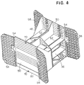
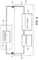
- FIGS. 1 and 8 show one possible embodiment for a heat pipe network.
- each deployable heat radiator 56 is in thermal contact with the payload module 36 via a pair of looped heat pipes, portions of which are shown at reference numeral 72.
- Each looped heat pipe 72 originates in the interior of satellite 30 and extends to the exterior of deployable heat radiator 56 where it then returns back into the satellite 30 to where it originated so as to form a closed loop as shown in FIG. 8.
- the heat pipe 72 contains a fluid, such as liquid ammonia, and uses a capillary effect to transport hot vapor generated by the bus module 34 and payload module 36 to the deployable heat radiator 56.
- Heat pipe 72 transports vapor along its length, through a flex coil 74, to the deployable heat radiator 56 where heat is expelled from the spacecraft 30. Release of the heat results in the vapor cooling and entering the condensation chamber 76 where it condenses into a liquid.
- the condensed liquid is returned through a second flex coil 78 to the satellite 30 via capillary forces.
- the liquid then receives heat from one or more heat sources 80 on the spacecraft 30 and is vaporized in evaporator 82 where then the above-described process is repeated.
- the above process occurs, with the exception of flex coils 74, 78, in a similar manner for the feed heat radiators 50.
- Heat pipe 72 preferably is bonded to the outer surface of the deployable heat radiator 56 by a film adhesive, such as BASF 1146. Thus, the heat is conductively transmitted to the deployable heat radiator 56 which then transmits the heat into outer space.
- a film adhesive such as BASF 1146.
- Flex coils 74, 78 are fastened on one end to a fixed heat radiator panel 50 and on the other end to a deployable heat radiator 56. As shown in FIG. 9, each flex coil 74, 78 has a flexible stainless steel outer sheath 84 and a corrugated bellows tube 86 within the sheath 84, such bellows tubes 86 being well-known in the art.
- the bellows tube 86 will also be made of a flexible metal material.
- flex coils 74, 78 are located substantially between the fixed radiator 50 and the deployable heat radiator 56. Furthermore, the individual flex coils 74, 78 are concentric with each other.
- FIGS. 12 and 13 illustrate the position of flex coils 74, 78 relative to the hinge axis A, after the deployable heat radiators 56 move to the deployed position.
- the flex coils 74, 78 are pivoted on the fixed heat radiator panels 50, and stretch and sweep in an arcuate fashion during deployment.
- the flex coils 74, 78 complete their arcuate sweep in substantially the same plane on which the flex coils 74, 78 rested while in the stowed position.
- the flex coils 74, 78 accordingly, do not twist or bend. This prevents the flex coils 74, 78 from overstressing or collapsing on themselves, and ultimately interfering with the heat rejection process.
- the coils 74, 78 are no longer concentric and only a portion of the flex coils 74, 78 are aligned with the hinge axis A.
- flex coils 74, 78 are positioned such that they will not make contact with a pivot member 58 whether a deployable heat radiator 56 is in the stowed or deployed positions.
- flex coils 74, 78 are made of a flexible material, such as aluminum, and have a serpentine shape to transport the vapor to the deployable heat radiator 56 and return the condensed liquid from the deployable heat radiator 56 to the evaporator 82 located on the satellite 30.
- flex coils 74, 78 are fastened on one end to the fixed radiator panel 50 and on the other end to the deployable heat radiator 56.
- the serpentine sections each have a shape which is very similar to the shape of the cooling coils of a refrigerator.
- FIG. 14 is an illustration of the positioning of a serpentine flex coil 74, 78 relative to hinge axis A when deployable heat radiator 56 is in a stowed position.
- FIG. 14 illustrates that the flex coils 74, 78 can be in front of, aligned with or in back of the axis of rotation A.
- the serpentine flex coil 74, 78 forms an arc between the fixed radiator panel 50 and the deployable heat radiator 56.
- flex coils 74, 78 are each folded over itself which tends to compress its loops.
- FIG. 15 is a side view of the serpentine flex coils 74, 78 in the stowed position.
- FIG. 16 also shows the U-shaped curves that make-up the serpentine flex coils 74, 78.
- FIG. 16 illustrates the path of a flex coil 74, 78 relative to a hinge axis A, where portions of the serpentine flex coils 74, 78 are shown passing through the hinge axis A and unfolding as the deployable heat radiator 56 deploys. If the deployable heat radiator 56 is fully deployed, the serpentine flex coil 74, 78 will lie in substantially the same plane as the deployable heat radiator 56. This prevents the flex coil 74, 78 from overstressing, twisting or collapsing on itself, and ultimately from interfering with the heat rejection process. As with their coiled counterparts of FIGS.
- FIG. 17 is a top of view of the serpentine flex coil 74, 78 of FIG. 15 in the deployed position.
- FIG. 17 is an isometric view of a serpentine flex coil 74, 78 in the folded or stowed position, relative to an axis of rotation A for a deployable heat radiator 56.
- the flex coils 74, 78 will decompress and assist in the deployment of the deployable heat radiator 56 a first predetermined position to a second predetermined position with respect to the satellite 30.
- the deployable heat radiator 56 is rotated by a biasing mechanism.
- deployable heat radiator 56 is attached to the connectors 54 by a pivot member 58 which can include either pin 60 or hinge 62.
- a spring mechanism such as spring 88, can be employed which is attached to side panel 48 and deployable heat radiator 56 as shown in FIG. 7.
- the spring 88 is prestressed to bias the deployable heat radiator 56 to rotate about an axis of rotation A by a predetermined angular amount ⁇ so that the heat radiator 56 moves from the initial position to the deployed position when the launch locks 70 are disengaged from the deployable heat radiator 56 as shown in FIG. 6.
- the spring mechanism preferably includes a well known damping mechanism attached to side panel 48 and deployable heat radiator 56 that will counteract the spring bias so that the radiator will move to the predetermined angle ⁇ without overshooting or oscillating about ⁇ .
- FIGS. 19 and 20 Two possible embodiments for the spring mechanism are shown in FIGS. 19 and 20.
- a spring actuator 90 and a damper 92 located on either side of notch 68.
- Spring actuator 90 and damper 92 are attached to side panel 48 and deployable heat radiator 56 via a bracket 94.
- the spring actuator 90 includes an axle which allows pivoting motion of deployable heat radiator 56 about the axle.
- Spring actuator 90 also includes a spring that is prestressed and attached to the deployable heat radiator 56 so as to move it towards the predetermined position ⁇ .
- Damper 92 counteracts the spring actuator 90 so that the deployable heat radiator 56 rotates to the desired angle ⁇ without overshooting or oscillating about ⁇ .
- Damper 92 contains a fluid with a rotating wheel immersed therein. The rotating wheel's axle allows for pivoting of the deployable heat radiator 56.
- the fluid is chosen so it can withstand the rigors of space and provide sufficient damping of the wheel so that the deployable heat radiator 56 moves
- FIG. 20 shows that the spring actuator and damper can be combined into a single mechanism 96 which is attached to a bracket 98 that is connected to both the side wall 48 and deployable heat radiator 56.
- Mechanism 96 has an axle which allows the deployable heat radiator 56 to pivot thereabout.
- mechanism 96 includes a spring which moves the deployable heat radiator 56 towards the predetermined position.
- Mechanism 96 further includes a damper to slow the inertia of the deployable heat radiator 56 caused by the spring so that the deployable heat radiator 56 rests at the predetermined position without overshooting or oscillating about the predetermined position.
- ⁇ will typically range from approximately 135° to less than 180°.
- the interference is reduced and since the field of view is less than 18°, it is possible to reposition the antennae so that they can receive angles within the 6° of angle that is unblocked by the radiators 56.
- the deployable heat radiator 56 may be at an initial position where interference is minimized, but a movement of the solar panels 42 and antennae 44 will upset this balance so that interference will increase.
- the pivot member 58 can be coupled to a motor 100 (located within either module 32 or 34 and denoted by dashed lines) so the motor 100 rotates the deployable heat radiator 56 by an angular amount ⁇ from the initial position to a second position so that interference is reduced or minimized. Constructing a motor 100 to rotate an object is, in general, well within the capability of one of ordinary skill in the art. Motor 100 receives a command signal from on board or from the ground via antennae 44 and reflectors 46 which directs the motor 100 to rotate the deployable heat radiator 56 by ⁇ to reduce or minimize interference.
- the present invention regards a deployable heat radiator in which the position of the deployable heat radiator can be controlled to such an extent that interference with antennae transmissions is reduced.
Landscapes
- Engineering & Computer Science (AREA)
- Life Sciences & Earth Sciences (AREA)
- Aviation & Aerospace Engineering (AREA)
- Remote Sensing (AREA)
- Environmental Sciences (AREA)
- General Health & Medical Sciences (AREA)
- Toxicology (AREA)
- Health & Medical Sciences (AREA)
- Environmental & Geological Engineering (AREA)
- Biodiversity & Conservation Biology (AREA)
- Sustainable Development (AREA)
- Physics & Mathematics (AREA)
- Thermal Sciences (AREA)
- Mechanical Engineering (AREA)
- General Engineering & Computer Science (AREA)
- Aerials With Secondary Devices (AREA)
- Details Of Aerials (AREA)
Abstract
A spacecraft (30) has a spacecraft body (32) and a heat radiator (56) attached to the spacecraft body (32). The heat radiator (56) is in thermal contact with the spacecraft body (32) and the heat radiator (56) moves from an initial position to a deployed position where heat is emitted therefrom. The predetermined deployed position is located at an angular position θ as measured relative to the initial position, wherein θ ranges from approximately 135° to less than 180°.
Description
- Spacecraft use a variety of structures to expel or dump heat from the spacecraft into outer space. One such structure is generally known as a deployable radiator. Deployable radiators are initially stored adjacent and parallel to a side panel of the spacecraft and then are deployed to a fixed position by rotating the radiator with respect to a hinge axis. One example of a deployable radiator is disclosed in U.S. Patent No. 5,117,901 where the radiator is deployed by 90° relative to an initial position. Typically, the radiator is rotated by 180° to be perpendicular to the side panel and spacecraft. In its deployed position, the radiator can unnecessarily interfere with the transmission of an antenna located on the spacecraft. For example, spacecraft typically are located in an orbit where the Earth subtends an angle of approximately 18° with respect to the spacecraft, where the spacecraft is the apex of the angle. This means that the antennae of the spacecraft must be positioned within this angle to receive or transmit information. When prior radiators are rotated to the 180° position, the radiators block an angle or field of view of approximately 24°. Thus, the extended radiators tend to block the 18° field of view and, thus, there will be interference with the radio transmissions received by and transmitted by the spacecraft antennae.
- The present invention provides a deployable radiator for a spacecraft. In particular, the deployable radiator of the present invention is capable of reducing interference with the transmission of antenna located on the spacecraft.
- In particular, the present invention concerns a spacecraft having a spacecraft body and a heat radiator attached to the spacecraft body. The heat radiator is in thermal contact with the spacecraft body and the heat radiator moves from an initial position to a deployed position where heat is emitted therefrom. The predetermined deployed position is located at an angular position θ as measured relative to the initial position, wherein θ ranges from approximately 135° to less than 180°.
- Another aspect of the present invention is a method of expelling heat generated on a spacecraft body of a spacecraft. The method entails the steps of placing a heat radiator in thermal contact with the spacecraft body and moving the heat radiator from an initial position to a deployed position which is located at an angular position θ as measured relative to the initial position, wherein θ ranges from approximately 135° to less than 180°. The method also entails emitting heat from the heat radiator at the deployed position.
- The above-described deployable radiator of the present invention reduces the amount of interference with the transmission of an antenna.
- The foregoing features and advantages of the present invention will be further understood upon consideration of the following detailed description of the invention taken in conjunction with the accompanying drawings, in which:
-
- FIG. 1 shows a spacecraft capable of utilizing a movable heat radiator of the present invention;
- FIG. 2 shows the heat radiator in a retracted or stowed configuration for the spacecraft of FIG. 1;
- FIG. 3 shows an enlarged view of the heat radiator in a retracted or stowed configuration for the spacecraft of FIG. 1;
- FIG. 4 shows a partially cut away view of the heat radiator in a deployed configuration for the spacecraft of FIG. 1;
- FIG. 5 shows a top view of the heat radiator of FIG. 1;
- FIG. 6 shows a cross-sectional view of the heat radiator of FIG. 1;
- FIG. 7 schematically shows a hinge to be used with the movable heat radiator of FIG. 6;
- FIG. 8 schematically shows a closed loop heat pipe network to be used with the spacecraft of FIG. 1;
- FIG. 9 shows the bellows structure of a flex coil used with the heat pipe network of FIG. 8;
- FIG. 10 shows an embodiment of a flex coil to be used with the closed loop heat pipe network of FIG. 8 when in a stowed configuration;
- FIG. 11 shows a side view of the flex coil of FIG. 10;
- FIG. 12 shows the flex coil of FIG. 10 when in a deployed position;
- FIG. 13 shows a side view of the flex coil of FIG. 12;
- FIG. 14 shows a second embodiment of a flex coil to be used with the closed loop heat pipe network of FIG. 8 when in a stowed configuration;
- FIG. 15 shows a side view of the flex coil of FIG. 14;
- FIG. 16 shows an isometric view of the flex coil of FIG. 14;
- FIG. 17 shows the flex coil of FIG. 14 when in a deployed position;
- FIG. 18 shows a side view of the flex coil of FIG. 17;
- FIG. 19 shows an embodiment of a spring mechanism capable of being utilized with the movable radiator of the present invention; and
- FIG. 20 shows another embodiment of a spring mechanism capable of being utilized with the movable radiator of the present invention.
- A spacecraft or
satellite 30 capable of utilizing the deployable radiator of the present invention is shown in FIGS. 1-2.Satellite 30 has aspacecraft body 32 which includes alower bus module 34 and anupper payload module 36. Attached to the aft end of thelower bus module 34 are a plurality of engines. These engines include a centrally positioned liquid orbital thruster (not shown) and fourchemical propulsion engines 38 located at the corners of thebus module 34 and two pairs of xenonion propulsion engines 40.Lower bus module 34 contains propellant tanks (not shown) and various power and control electronics which operate the engines and power thepayload module 36.Bus module 34 further includes a pair ofsolar panels 42 which convert sunlight into electricity that is sent to batteries (not shown) located on thebus module 34.Bus module 34 andpayload module 36 also support one or more receivers, such asantennae 44 andreflectors 46, which can be used to receive control signals from a ground station, and also send signals to the ground station. -
Payload module 36 is attached to thebus module 34 and contains a variety of electronic equipment which may include additional communication antennae (not shown). The electronic equipment processes information gathered by theantennae 34 andreflectors 36, and sends the processed information back to the ground station viaantennae 34 and/orreflectors 36. -
Payload module 36 has fourside panels 48 which meet at four corners. As shown in FIGS. 3 and 4, two or more of theside panels 48 may be fixedheat radiators 50 that have one ormore heat pipes 52 in thermal communication with thefixed radiator 50. The operation ofheat pipes 52 will be explained in detail below. At each corner of theside panels 48 are a pair ofconnectors 54 which are hingedly attached to adeployable heat radiator 56 via apivot member 58. As shown in FIG. 5,pivot member 58 may include a pair of pins orrods 60 extending from each end of thedeployable heat radiator 56. In this case, eachconnector 54 preferably has an opening to receive and engage one of the pins orrods 60. Thedeployable heat radiator 56 is then able to rotate about an axis, A, aligned with the longitudinal axis of the pins orrods 60, as shown in FIG. 6. - In another embodiment shown in FIG. 7, the
pivot member 58 may be one ormore hinges 62 which are attached to thedeployable heat radiator 56 and the outboard side ofside panel 48 in a well known manner, such asrivets 64. Like the embodiment withpins 60, thedeployable heat radiator 56 is able to rotate about an axis, A, defined by thehinge 62. - As shown in FIG. 5, each
deployable heat radiator 56 is generally rectangular in shape with a pair oftruncated corners 66 and anotch 68.Deployable heat radiator 56 preferably has a length of approximately 84", a width of approximately 37" and a thickness of approximately 1". Thedeployable heat radiator 56 is constructed by using a rectangular honeycomb structure made from aluminum or kevlar and having dimensions corresponding to that of thedeployable heat radiator 56. Such a honeycomb structure is available from various sources, such as the Excel, Unicel or Plascore companies. The honeycomb structure then has a pair of rectangular aluminum sheets which are attached to each side of the honeycomb structure via a room temperature vulcanized rubber or by well known film adhesive, such as those film adhesives known by the names of FM 300 or BASF 1146. In the case of attachment via vulcanized rubber, the rubber is preferably loaded with an iron filler thereby increasing the thermal conductivity of the rubber. Furthermore, the exterior of thedeployable heat radiator 56 may be further blanketed with KAPTON™, which is a neutral layer that limits the radiation of heat on both sides of the radiator. For increased radiative capability, glass mirrors (not shown) are bonded on top of the aluminum substrate. It is understood that other materials for the honeycomb structure which have similar structural and thermophysical properties as aluminum or kevlar could be substituted without straying from the scope of the present invention. Thetruncated corners 66 and notch 68 are shaped so that any latches or launch locks (not shown) used on thesolar panels 42 can be accommodated when thesatellite 30 is in the stowed configuration, as shown in FIGS. 2 and 3. - As shown in FIG. 3, one or more latches or launch
locks 70 attached to thepayload module 36 retain thedeployable heat radiators 56 in a stowed or initial position adjacent to and parallel to aside panel 48 of thepayload module 36 during launch of thesatellite 30. An example oflaunch lock 70 and its attachment to thedeployable heat radiator 56 is a well known bolt cutter-type mechanism. Thesolar panels 42 are folded also so as to cover thedeployable heat radiators 56. In an embodiment not shown, the initial position of thedeployable heat radiators 56 may lie within thespacecraft body 32 itself to provide additional protection for thedeployable heat radiator 56. - After the
satellite 30 is launched, it leaves the launch vehicle (not shown). At this stage of the mission, thesatellite 30 will propel itself along a transfer orbit to a position in space where it can enter a desired geosynchronous orbit. However, prior to entering the transfer orbit,antennae 44 andreflectors 46 receive a command signal from the ground station. A signal is sent to thesolar panels 42 which causes them to unfold to the configuration shown in FIG. 1. Thesolar panels 42 are deployed to power thexenon thrusters 40 that propel thesatellite 30 along the transfer orbit. As shown in FIGS. 2 and 3, launch locks 70 retain eachdeployable heat radiator 56 in its stowed configuration while thesatellite 30 moves in the transfer orbit. The extreme temperatures encountered during the transfer orbit reduce the need to reject heat from thesatellite 30. Since thedeployable heat radiators 56 are not needed to perform their main function of expelling heat, they preferably each cover a fixedheat radiator 50 to insulate thesatellite 30 from the extreme cold space temperature. The KAPTON™ blanket on the exterior of thedeployable heat radiators 56 adds an additional layer of insulation to protect the fixedradiators 50. - After the transfer orbit is achieved, a second signal is sent either automatically or via ground command signal to the launch locks 70 when heat rejection from within the
satellite 30 is necessary, causing the launch locks 70 to disengage from thedeployable heat radiators 56. In one embodiment, the launch locks 70 are opened by detonating explosive charges in thelocks 70. Disengagement from the launching locks 70 results in thedeployable heat radiators 56 moving from their initial stowed position to a deployed position, as shown in FIGS. 6 and 7, where heat is emitted from thedeployable heat radiators 56. - In the deployed position, a closed network of
heat pipes satellite 30 to the fixed and deployable heat radiators, respectively. FIGS. 1 and 8 show one possible embodiment for a heat pipe network. In particular, eachdeployable heat radiator 56 is in thermal contact with thepayload module 36 via a pair of looped heat pipes, portions of which are shown atreference numeral 72. Each loopedheat pipe 72 originates in the interior ofsatellite 30 and extends to the exterior ofdeployable heat radiator 56 where it then returns back into thesatellite 30 to where it originated so as to form a closed loop as shown in FIG. 8. Theheat pipe 72 contains a fluid, such as liquid ammonia, and uses a capillary effect to transport hot vapor generated by thebus module 34 andpayload module 36 to thedeployable heat radiator 56.Heat pipe 72 transports vapor along its length, through aflex coil 74, to thedeployable heat radiator 56 where heat is expelled from thespacecraft 30. Release of the heat results in the vapor cooling and entering thecondensation chamber 76 where it condenses into a liquid. The condensed liquid is returned through asecond flex coil 78 to thesatellite 30 via capillary forces. The liquid then receives heat from one ormore heat sources 80 on thespacecraft 30 and is vaporized inevaporator 82 where then the above-described process is repeated. The above process occurs, with the exception of flex coils 74, 78, in a similar manner for thefeed heat radiators 50. -
Heat pipe 72 preferably is bonded to the outer surface of thedeployable heat radiator 56 by a film adhesive, such as BASF 1146. Thus, the heat is conductively transmitted to thedeployable heat radiator 56 which then transmits the heat into outer space. An example of a possible composition for aheat pipe 72 in general is disclosed in U.S. Patent No. 4,515,209, whose contents are incorporated herein by reference. - Flex coils 74, 78 are fastened on one end to a fixed
heat radiator panel 50 and on the other end to adeployable heat radiator 56. As shown in FIG. 9, eachflex coil outer sheath 84 and a corrugated bellowstube 86 within thesheath 84,such bellows tubes 86 being well-known in the art. Thebellows tube 86 will also be made of a flexible metal material. - In the stowed configuration of FIGS. 10 and 11, flex coils 74, 78 are located substantially between the fixed
radiator 50 and thedeployable heat radiator 56. Furthermore, the individual flex coils 74, 78 are concentric with each other. - FIGS. 12 and 13 illustrate the position of flex coils 74, 78 relative to the hinge axis A, after the
deployable heat radiators 56 move to the deployed position. The flex coils 74, 78 are pivoted on the fixedheat radiator panels 50, and stretch and sweep in an arcuate fashion during deployment. The flex coils 74, 78 complete their arcuate sweep in substantially the same plane on which the flex coils 74, 78 rested while in the stowed position. The flex coils 74, 78 accordingly, do not twist or bend. This prevents the flex coils 74, 78 from overstressing or collapsing on themselves, and ultimately interfering with the heat rejection process. After thedeployable heat radiators 56 are deployed, thecoils pivot member 58 whether adeployable heat radiator 56 is in the stowed or deployed positions. - Another possible embodiment for flex coils 74, 78 is shown in FIGS. 14-18. Instead of the circular coiled shape of FIGS. 10-13, flex coils 74, 78 each are made of a flexible material, such as aluminum, and have a serpentine shape to transport the vapor to the
deployable heat radiator 56 and return the condensed liquid from thedeployable heat radiator 56 to theevaporator 82 located on thesatellite 30. As with the coiled embodiment of FIGS. 10-13, flex coils 74, 78 are fastened on one end to the fixedradiator panel 50 and on the other end to thedeployable heat radiator 56. Note that the serpentine sections each have a shape which is very similar to the shape of the cooling coils of a refrigerator. - FIG. 14 is an illustration of the positioning of a
serpentine flex coil deployable heat radiator 56 is in a stowed position. FIG. 14 illustrates that the flex coils 74, 78 can be in front of, aligned with or in back of the axis of rotation A. Theserpentine flex coil radiator panel 50 and thedeployable heat radiator 56. In addition, flex coils 74, 78 are each folded over itself which tends to compress its loops. FIG. 15 is a side view of the serpentine flex coils 74, 78 in the stowed position. FIG. 16 also shows the U-shaped curves that make-up the serpentine flex coils 74, 78. - FIG. 16 illustrates the path of a
flex coil deployable heat radiator 56 deploys. If thedeployable heat radiator 56 is fully deployed, theserpentine flex coil deployable heat radiator 56. This prevents theflex coil pivot member 58, notwithstanding that adeployable heat radiator 56 is in the stowed or deployed position. FIG. 17 is a top of view of theserpentine flex coil serpentine flex coil deployable heat radiator 56. - For both embodiments of the flex coils 74, 78 described above with respect to FIGS. 10-18, once the launch locks 70 are opened, the flex coils 74, 78 will decompress and assist in the deployment of the deployable heat radiator 56 a first predetermined position to a second predetermined position with respect to the
satellite 30. - Besides flex coils 74, 78, the
deployable heat radiator 56 is rotated by a biasing mechanism. As mentioned previously,deployable heat radiator 56 is attached to theconnectors 54 by apivot member 58 which can include eitherpin 60 orhinge 62. In both embodiments, a spring mechanism, such asspring 88, can be employed which is attached toside panel 48 anddeployable heat radiator 56 as shown in FIG. 7. Thespring 88 is prestressed to bias thedeployable heat radiator 56 to rotate about an axis of rotation A by a predetermined angular amount θ so that theheat radiator 56 moves from the initial position to the deployed position when the launch locks 70 are disengaged from thedeployable heat radiator 56 as shown in FIG. 6. The spring mechanism preferably includes a well known damping mechanism attached toside panel 48 anddeployable heat radiator 56 that will counteract the spring bias so that the radiator will move to the predetermined angle θ without overshooting or oscillating about θ. - Two possible embodiments for the spring mechanism are shown in FIGS. 19 and 20. In FIG. 19, there is shown a
spring actuator 90 and adamper 92 located on either side ofnotch 68.Spring actuator 90 anddamper 92 are attached toside panel 48 anddeployable heat radiator 56 via abracket 94. Thespring actuator 90 includes an axle which allows pivoting motion ofdeployable heat radiator 56 about the axle.Spring actuator 90 also includes a spring that is prestressed and attached to thedeployable heat radiator 56 so as to move it towards the predetermined position θ.Damper 92 counteracts thespring actuator 90 so that thedeployable heat radiator 56 rotates to the desired angle θ without overshooting or oscillating about θ.Damper 92 contains a fluid with a rotating wheel immersed therein. The rotating wheel's axle allows for pivoting of thedeployable heat radiator 56. Furthermore, the fluid is chosen so it can withstand the rigors of space and provide sufficient damping of the wheel so that thedeployable heat radiator 56 moves to the predetermined position. - Another possible embodiment for the spring mechanism is shown in FIG. 20. FIG. 20 shows that the spring actuator and damper can be combined into a
single mechanism 96 which is attached to abracket 98 that is connected to both theside wall 48 anddeployable heat radiator 56.Mechanism 96 has an axle which allows thedeployable heat radiator 56 to pivot thereabout. As before,mechanism 96 includes a spring which moves thedeployable heat radiator 56 towards the predetermined position.Mechanism 96 further includes a damper to slow the inertia of thedeployable heat radiator 56 caused by the spring so that thedeployable heat radiator 56 rests at the predetermined position without overshooting or oscillating about the predetermined position. When either of the embodiments of the flex coils 74, 78 are used in combination withspring 78,spring actuator 90 ormechanism 96 they together make up the spring mechanism so as to bias thedeployable heat radiator 56 to the deployed position by an angular amount θ relative to the initial position. θ will typically range from approximately 135° to less than 180°. - As mentioned previously, prior fixed heat radiators are unfolded by θ=180° to the deployed position so that they subtend a field of view corresponding to an angle of approximately 24° (12° half angle). Since this angle is greater than the 18° angle needed for transmission by the antennae, interference will result. To overcome this deficiency, the predetermined deployed position can be chosen such that the amount that the
deployable heat radiator 56 blocks transmissions from theantennae 44 is reduced by as much as approximately 40% when compared with prior radiator geometries, where the radiator is deployed to an angle θ=180° as measured relative to its initial position when folded parallel to the spacecraft body. By deploying theradiator 56 by an angular amount θ ranging from 135° to less than 180°, the present invention reduces the field of view blocked by theradiators 56 to approximately 14° (θ=135°), a reduction of almost 42%. Thus, the interference is reduced and since the field of view is less than 18°, it is possible to reposition the antennae so that they can receive angles within the 6° of angle that is unblocked by theradiators 56. - Many times antennae interference will be caused by the independent movement of the
solar panels 42 andantennae 44. For example, thedeployable heat radiator 56 may be at an initial position where interference is minimized, but a movement of thesolar panels 42 andantennae 44 will upset this balance so that interference will increase. In this case, thepivot member 58 can be coupled to a motor 100 (located within eithermodule motor 100 rotates thedeployable heat radiator 56 by an angular amount θ from the initial position to a second position so that interference is reduced or minimized. Constructing amotor 100 to rotate an object is, in general, well within the capability of one of ordinary skill in the art.Motor 100 receives a command signal from on board or from the ground viaantennae 44 andreflectors 46 which directs themotor 100 to rotate thedeployable heat radiator 56 by θ to reduce or minimize interference. - Summarizing, the present invention regards a deployable heat radiator in which the position of the deployable heat radiator can be controlled to such an extent that interference with antennae transmissions is reduced.
- The foregoing description is provided to illustrate the invention, and is not to be construed as a limitation. Numerous additions, substitutions and other changes can be made to the invention without departing from its scope as set forth in the appended claims. For example, one or more sections of the heat pipe network is shielded from deleterious elements in outer space such as micrometeorites.
Claims (7)
1. A spacecraft comprising:
a spacecraft body (32);
a heat radiator (56) attached to said spacecraft body (32) and in thermal contact with said spacecraft body (32), wherein said heat radiator (56) moves from an initial position to a predetermined deployed position where heat is emitted therefrom;
said predetermined deployed position is located at an angular position θ as measured relative to said initial position, wherein θ ranges from approximately 135° to less than 180°.
2. The spacecraft of claim 1, characterized in that it comprises a pivot member (58) for attaching said heat radiator (56) to said spacecraft body (32) and pivoting said heat radiator (56) about an axis of rotation (A) to said predetermined deployed position.
3. The spacecraft of claim 2, characterized in that said pivot member (58) comprises a spring mechanism (88, 90, 96) for biasing said heat radiator (56) to move from said initial position to said deployed position; and
said spacecraft (30) further comprises a damper (92) to damp the movement of said radiator (56) in response to said spring mechanism (88, 90, 96) so that said radiator (56) does not overshoot or oscillate about said predetermined deployed position.
said spacecraft (30) further comprises a damper (92) to damp the movement of said radiator (56) in response to said spring mechanism (88, 90, 96) so that said radiator (56) does not overshoot or oscillate about said predetermined deployed position.
7. The method of claim 6, characterized in that said moving step comprises pivoting said heat radiator (56) about an axis of rotation (A) by an amount θ so that said heat radiator (56) moves from said initial position to said deployed position.
8. The method of claim 6 or 7, characterized in that an antenna (44) is attached to said spacecraft body (32); and
said deployed position corresponds to the position where the amount that said heat radiator (56) blocks transmissions from said antenna (44) is reduced by approximately 40 % in comparison with said heat radiator (56) being located at a deployed position of approximately θ = 180°.
said deployed position corresponds to the position where the amount that said heat radiator (56) blocks transmissions from said antenna (44) is reduced by approximately 40 % in comparison with said heat radiator (56) being located at a deployed position of approximately θ = 180°.
9. The method of any of claims 6 through 8, characterized by the step of:
damping the movement of said radiator (56) so that said radiator (56) does not overshoot or oscillate about said predetermined deployed position.
10. The method of any of claims 6 through 9, characterized in that said movement of said heat radiator (56) is in response to a command signal.
Applications Claiming Priority (2)
| Application Number | Priority Date | Filing Date | Title |
|---|---|---|---|
| US577439 | 1995-12-22 | ||
| US08/577,439 US5732765A (en) | 1995-12-22 | 1995-12-22 | Adjustable heat rejection system |
Publications (1)
| Publication Number | Publication Date |
|---|---|
| EP0786404A1 true EP0786404A1 (en) | 1997-07-30 |
Family
ID=24308740
Family Applications (1)
| Application Number | Title | Priority Date | Filing Date |
|---|---|---|---|
| EP96120398A Ceased EP0786404A1 (en) | 1995-12-22 | 1996-12-18 | Adjustable heat rejection system |
Country Status (2)
| Country | Link |
|---|---|
| US (1) | US5732765A (en) |
| EP (1) | EP0786404A1 (en) |
Cited By (8)
| Publication number | Priority date | Publication date | Assignee | Title |
|---|---|---|---|---|
| EP0942867A4 (en) * | 1997-10-10 | 2000-07-26 | Loral Space Systems Inc | Aft deployable thermal radiators for spacecraft |
| FR2840394A1 (en) * | 2002-05-30 | 2003-12-05 | Cit Alcatel | HEAT TRANSFER DEVICE FOR SATELLITE COMPRISING AN EVAPORATOR |
| US20110277959A1 (en) * | 2010-05-14 | 2011-11-17 | Paragon Space Development Corporation | Radiator Systems |
| US8096512B2 (en) | 2004-02-19 | 2012-01-17 | Astrium Limited | Payload modules |
| EP3239057A1 (en) * | 2016-04-26 | 2017-11-01 | Airbus Defence and Space Netherlands B.V. | Solar panel and flexible radiator for a spacecraft |
| EP3381814A1 (en) * | 2017-03-27 | 2018-10-03 | Space Systems/Loral, LLC | A spacecraft |
| US20190315501A1 (en) * | 2018-04-17 | 2019-10-17 | Raytheon Company | Thermally-enhanced and deployable structures |
| EP3524528B1 (en) * | 2016-10-09 | 2023-08-23 | Haikou Institute Of Future Technology | Near space aircraft pod |
Families Citing this family (39)
| Publication number | Priority date | Publication date | Assignee | Title |
|---|---|---|---|---|
| GB9616016D0 (en) * | 1996-07-31 | 1996-09-11 | Matra Marconi Space Uk Ltd | Deployable radiators for spacecraft |
| US5910883A (en) * | 1997-08-06 | 1999-06-08 | International Business Machines Corporation | Hinge incorporating a helically coiled heat pipe for a laptop computer |
| US6776220B1 (en) * | 1999-08-19 | 2004-08-17 | Space Systems/Loral, Inc | Spacecraft radiator system using crossing heat pipes |
| US6595470B2 (en) | 2001-11-02 | 2003-07-22 | The Boeing Company | Deployable radiator with flexible line loop |
| US20050180109A1 (en) * | 2002-04-16 | 2005-08-18 | Yoshiro Miyazaki | Self-excited vibration heat pipe and computer with the heat pipe |
| US7080681B2 (en) * | 2004-03-03 | 2006-07-25 | Thermal Corp. | Heat pipe component deployed from a compact volume |
| US8720530B2 (en) * | 2006-05-17 | 2014-05-13 | The Boeing Company | Multi-layer wick in loop heat pipe |
| US8286696B2 (en) * | 2007-06-22 | 2012-10-16 | The Boeing Company | Mechanically actuated thermal switch |
| DK2325483T3 (en) * | 2009-11-24 | 2012-11-19 | Siemens Ag | Device with a modular nacelle with a radiator |
| EP2325482B1 (en) * | 2009-11-24 | 2014-01-01 | Siemens Aktiengesellschaft | Arrangement with a nacelle and a radiator |
| US20110174298A1 (en) * | 2010-01-21 | 2011-07-21 | Aldrich Steven J | Methods and systems for high-performance solar radiation collection |
| US8675363B2 (en) * | 2011-07-26 | 2014-03-18 | Hewlett-Packard Development Company, L.P. | Thermal conductors in electronic devices |
| WO2013100946A1 (en) | 2011-12-28 | 2013-07-04 | Intel Corporation | Electronic device having a passive heat exchange device |
| US8960608B2 (en) | 2012-02-07 | 2015-02-24 | Lockheed Martin Corporation | Deployable radiator having an increased view factor |
| US8714492B2 (en) * | 2012-02-07 | 2014-05-06 | Lockheed Martin Corporation | Non-interfering deployable radiator arrangement for geo spacecraft |
| US9134757B2 (en) * | 2012-09-28 | 2015-09-15 | Intel Corporation | Electronic device having passive cooling |
| US8982555B2 (en) * | 2012-09-28 | 2015-03-17 | Intel Corporation | Electronic device having passive cooling |
| US9036353B2 (en) * | 2012-11-26 | 2015-05-19 | Northrop Grumman Systems Corporation | Flexible thermal interface for electronics |
| US9889951B1 (en) * | 2013-02-12 | 2018-02-13 | Lockheed Martin Corporation | Spacecraft east-west radiator assembly |
| US9352855B2 (en) * | 2013-04-09 | 2016-05-31 | Lockheed Martin Corporation | Heat generating transfer orbit shield |
| US20150069187A1 (en) * | 2013-09-09 | 2015-03-12 | Lockheed Martin Corporation | Hosted instrument radiator system |
| US9352856B1 (en) * | 2013-12-04 | 2016-05-31 | Space Systems/Loral, Llc | Axially grooved crossing heat pipes |
| US11186387B2 (en) * | 2014-12-04 | 2021-11-30 | Evening Star Technology Development Ltd. | Variable heat rejection device |
| US10228197B2 (en) * | 2014-12-04 | 2019-03-12 | Thomas Jaspero Cognata | Variable heat rejection device |
| FR3031969B1 (en) * | 2015-01-27 | 2017-01-27 | Airbus Defence & Space Sas | ARTIFICIAL SATELLITE AND METHOD FOR FILLING A PROPULSIVE GAS TANK OF SAID ARTIFICIAL SATELLITE |
| JP6448819B2 (en) * | 2015-06-02 | 2019-01-09 | エアバス ディフェンス アンド スペース エスアーエス | Satellite |
| US9908643B2 (en) * | 2015-08-05 | 2018-03-06 | Worldvu Satellites Limited | Passive thermal system providing an embedded interface for heat pipes |
| US10407189B1 (en) * | 2016-10-27 | 2019-09-10 | Space Systems/Loral, Llc | Spacecraft exoskeleton truss structure |
| US11286062B1 (en) | 2016-10-27 | 2022-03-29 | Space Systems/Loral, Llc | Spacecraft exoskeleton truss structure |
| US11492145B2 (en) * | 2016-12-19 | 2022-11-08 | Mitsubishi Electric Corporation | Deployable radiator |
| US10633123B2 (en) | 2017-04-05 | 2020-04-28 | Space Systems/Loral, Llc | Exoskeletal launch support structure |
| US10812012B2 (en) * | 2018-03-01 | 2020-10-20 | Tesla, Inc. | Hinging inverted seam module mounting system |
| US11459127B2 (en) | 2018-04-17 | 2022-10-04 | Raytheon Company | Integrated thermal energy transport and storage structures |
| WO2019204322A1 (en) * | 2018-04-17 | 2019-10-24 | Raytheon Company | Thermally-enhanced and deployable structures |
| US20200191497A1 (en) * | 2018-10-24 | 2020-06-18 | Roccor, Llc | Deployable Radiator Devices, Systems, and Methods Utilizing Composite Laminates |
| JP6625302B1 (en) * | 2019-04-22 | 2019-12-25 | 三菱電機株式会社 | Electronics |
| WO2021054755A1 (en) * | 2019-09-19 | 2021-03-25 | 주식회사 케이엠더블유 | Antenna device |
| US20230070583A1 (en) * | 2021-09-07 | 2023-03-09 | Kyle Borden Marquis | Kinked Thin Tube for Fluid-Pressurized Deployment |
| CN115507684B (en) * | 2022-11-18 | 2023-03-03 | 上海航天空间技术有限公司 | U-shaped heat pipe supporting and auxiliary installation tool |
Citations (8)
| Publication number | Priority date | Publication date | Assignee | Title |
|---|---|---|---|---|
| US3260305A (en) * | 1963-11-13 | 1966-07-12 | Gen Motors Corp | Folded radiator design |
| US3563307A (en) * | 1970-02-02 | 1971-02-16 | Nasa | Radiator deployment actuator |
| US4515209A (en) | 1984-04-03 | 1985-05-07 | Otdel Fiziko-Tekhnicheskikh Problem Energetiki Uralskogo Nauchnogo Tsentra Akademi Nauk Ssr | Heat transfer apparatus |
| US4561614A (en) * | 1982-12-07 | 1985-12-31 | Rca Corporation | Deployable folded multi-element satellite subsystems |
| US4738304A (en) * | 1986-03-12 | 1988-04-19 | Rca Corporation | Direct condensation radiator for spacecraft |
| US5027892A (en) * | 1989-07-13 | 1991-07-02 | Sundstrand Corporation | Petal deployable radiator system for spacecraft |
| US5117901A (en) | 1991-02-01 | 1992-06-02 | Cullimore Brent A | Heat transfer system having a flexible deployable condenser tube |
| US5356095A (en) * | 1992-08-04 | 1994-10-18 | Fairchild Space And Defense Corporation | Attenuating linged deployment apparatus |
-
1995
- 1995-12-22 US US08/577,439 patent/US5732765A/en not_active Expired - Lifetime
-
1996
- 1996-12-18 EP EP96120398A patent/EP0786404A1/en not_active Ceased
Patent Citations (8)
| Publication number | Priority date | Publication date | Assignee | Title |
|---|---|---|---|---|
| US3260305A (en) * | 1963-11-13 | 1966-07-12 | Gen Motors Corp | Folded radiator design |
| US3563307A (en) * | 1970-02-02 | 1971-02-16 | Nasa | Radiator deployment actuator |
| US4561614A (en) * | 1982-12-07 | 1985-12-31 | Rca Corporation | Deployable folded multi-element satellite subsystems |
| US4515209A (en) | 1984-04-03 | 1985-05-07 | Otdel Fiziko-Tekhnicheskikh Problem Energetiki Uralskogo Nauchnogo Tsentra Akademi Nauk Ssr | Heat transfer apparatus |
| US4738304A (en) * | 1986-03-12 | 1988-04-19 | Rca Corporation | Direct condensation radiator for spacecraft |
| US5027892A (en) * | 1989-07-13 | 1991-07-02 | Sundstrand Corporation | Petal deployable radiator system for spacecraft |
| US5117901A (en) | 1991-02-01 | 1992-06-02 | Cullimore Brent A | Heat transfer system having a flexible deployable condenser tube |
| US5356095A (en) * | 1992-08-04 | 1994-10-18 | Fairchild Space And Defense Corporation | Attenuating linged deployment apparatus |
Cited By (19)
| Publication number | Priority date | Publication date | Assignee | Title |
|---|---|---|---|---|
| US6378809B1 (en) | 1997-10-10 | 2002-04-30 | Space Systems | AFT deployable thermal radiators for spacecraft |
| EP0942867A4 (en) * | 1997-10-10 | 2000-07-26 | Loral Space Systems Inc | Aft deployable thermal radiators for spacecraft |
| FR2840394A1 (en) * | 2002-05-30 | 2003-12-05 | Cit Alcatel | HEAT TRANSFER DEVICE FOR SATELLITE COMPRISING AN EVAPORATOR |
| US7174950B2 (en) | 2002-05-30 | 2007-02-13 | Alcatel | Heat transfer system for a satellite including an evaporator |
| US8096512B2 (en) | 2004-02-19 | 2012-01-17 | Astrium Limited | Payload modules |
| US9429371B2 (en) * | 2010-05-14 | 2016-08-30 | Paragon Space Development Corporation | Radiator systems |
| US9962798B2 (en) | 2010-05-14 | 2018-05-08 | Paragon Space Development Corporation | Radiator systems |
| US20150285568A1 (en) * | 2010-05-14 | 2015-10-08 | Paragon Space Development Corporation | Radiator systems |
| US20110277959A1 (en) * | 2010-05-14 | 2011-11-17 | Paragon Space Development Corporation | Radiator Systems |
| US20160332268A1 (en) * | 2010-05-14 | 2016-11-17 | Paragon Space Development Corporation | Radiator systems |
| US9091489B2 (en) * | 2010-05-14 | 2015-07-28 | Paragon Space Development Corporation | Radiator systems |
| NL2016677B1 (en) * | 2016-04-26 | 2017-11-07 | Airbus Defence And Space Netherlands B V | Solar Panel and Flexible Radiator for a Spacecraft. |
| EP3239057A1 (en) * | 2016-04-26 | 2017-11-01 | Airbus Defence and Space Netherlands B.V. | Solar panel and flexible radiator for a spacecraft |
| US10737808B2 (en) | 2016-04-26 | 2020-08-11 | Airbus Defence And Space Netherlands B.V. | Solar panel and flexible radiator for a spacecraft |
| EP3524528B1 (en) * | 2016-10-09 | 2023-08-23 | Haikou Institute Of Future Technology | Near space aircraft pod |
| EP3381814A1 (en) * | 2017-03-27 | 2018-10-03 | Space Systems/Loral, LLC | A spacecraft |
| US10538346B2 (en) | 2017-03-27 | 2020-01-21 | Space Systems/Loral, Llc | Electric thruster waste heat recovery during satellite orbit transfer |
| US20190315501A1 (en) * | 2018-04-17 | 2019-10-17 | Raytheon Company | Thermally-enhanced and deployable structures |
| US12398704B2 (en) * | 2018-04-17 | 2025-08-26 | Raytheon Company | Thermally-enhanced and deployable structures |
Also Published As
| Publication number | Publication date |
|---|---|
| US5732765A (en) | 1998-03-31 |
Similar Documents
| Publication | Publication Date | Title |
|---|---|---|
| US5732765A (en) | Adjustable heat rejection system | |
| US5806800A (en) | Dual function deployable radiator cover | |
| EP0780293B1 (en) | Spacecraft with large east-west dimensions | |
| US20260015995A1 (en) | Thermally-Enhanced and Deployable Structures | |
| EP0822139B1 (en) | Deployable radiators for spacecraft | |
| US5927654A (en) | Spacecraft with active antenna array protected against temperature extremes | |
| EP3277587B1 (en) | Satellite radiator panels with combined stiffener/heat pipe | |
| EP1999023B1 (en) | Satellite with deployable, articulatable thermal radiators | |
| EP0780306B1 (en) | Flexible heat transport design for deployment applications | |
| JP2002308199A (en) | Deployable spacecraft radiator | |
| EP0942867A1 (en) | Aft deployable thermal radiators for spacecraft | |
| US20160305714A1 (en) | Fluidicially Coupled Heat Pipes and Method Therefor | |
| EP1735213B1 (en) | Deployable boom | |
| US6082678A (en) | Geostationary earth observation satellite incorporating multiple thruster liquid propellant apogee maneuver system | |
| US6854510B2 (en) | Spacecraft radiator system and method using cross-coupled deployable thermal radiators | |
| WO2017024187A1 (en) | Passive thermal system providing an embedded interface for heat pipes | |
| Mini et al. | European large deployable antenna: development status and applications | |
| Archer et al. | Antenna technology for QUASAT application | |
| Misawa et al. | Configuration and performance of 30/20 GHz band shaped-beam antenna for satellite use | |
| EP4477562A1 (en) | Two axis pointing mechanism | |
| Wang et al. | Review of Mechanical Technology of Communication Antenna Worked in High Temperature Environment for Deep Space Exploration | |
| Russell et al. | NASA technology for large space antennas | |
| Gurvits | A concept of the second generation Space VLBI mission | |
| WO2026069081A1 (en) | Deployable space antenna with rollable and/or z-foldable reflector array | |
| Imbriale | The Planetary Flybys |
Legal Events
| Date | Code | Title | Description |
|---|---|---|---|
| PUAI | Public reference made under article 153(3) epc to a published international application that has entered the european phase |
Free format text: ORIGINAL CODE: 0009012 |
|
| AK | Designated contracting states |
Kind code of ref document: A1 Designated state(s): DE FR GB |
|
| 17P | Request for examination filed |
Effective date: 19980126 |
|
| RAP1 | Party data changed (applicant data changed or rights of an application transferred) |
Owner name: HUGHES ELECTRONICS CORPORATION |
|
| 17Q | First examination report despatched |
Effective date: 20000607 |
|
| STAA | Information on the status of an ep patent application or granted ep patent |
Free format text: STATUS: THE APPLICATION HAS BEEN REFUSED |
|
| 18R | Application refused |
Effective date: 20041128 |