EP0786094B1 - System and method for making electromagnetic measurements using a transverse electromagnetic cell - Google Patents
System and method for making electromagnetic measurements using a transverse electromagnetic cell Download PDFInfo
- Publication number
- EP0786094B1 EP0786094B1 EP95936245A EP95936245A EP0786094B1 EP 0786094 B1 EP0786094 B1 EP 0786094B1 EP 95936245 A EP95936245 A EP 95936245A EP 95936245 A EP95936245 A EP 95936245A EP 0786094 B1 EP0786094 B1 EP 0786094B1
- Authority
- EP
- European Patent Office
- Prior art keywords
- cell
- axis
- hollow cell
- gravity
- force
- Prior art date
- Legal status (The legal status is an assumption and is not a legal conclusion. Google has not performed a legal analysis and makes no representation as to the accuracy of the status listed.)
- Expired - Lifetime
Links
Images






Classifications
-
- G—PHYSICS
- G01—MEASURING; TESTING
- G01R—MEASURING ELECTRIC VARIABLES; MEASURING MAGNETIC VARIABLES
- G01R29/00—Arrangements for measuring or indicating electric quantities not covered by groups G01R19/00 - G01R27/00
- G01R29/08—Measuring electromagnetic field characteristics
- G01R29/0807—Measuring electromagnetic field characteristics characterised by the application
- G01R29/0814—Field measurements related to measuring influence on or from apparatus, components or humans, e.g. in ESD, EMI, EMC, EMP testing, measuring radiation leakage; detecting presence of micro- or radiowave emitters; dosimetry; testing shielding; measurements related to lightning
- G01R29/0821—Field measurements related to measuring influence on or from apparatus, components or humans, e.g. in ESD, EMI, EMC, EMP testing, measuring radiation leakage; detecting presence of micro- or radiowave emitters; dosimetry; testing shielding; measurements related to lightning rooms and test sites therefor, e.g. anechoic chambers, open field sites or TEM cells
- G01R29/0828—TEM-cells
Definitions
- the present invention relates to a system and method for making electromagnetic measurements of a test object (also known as equipment under test (EUT)) using a transverse electromagnetic (TEM) cell. More specifically, the present invention relates to a system and method for maintaining the EUT in a fixed tilt position and, as contemplated by various embodiments, a horizontal (i.e., "gravity-down") position as the TEM cell is tilted and EUT rotated to specified angles. The electromagnetic readings taken at those angles are then processed to measure the electric field and the magnetic field produced by the EUT.
- a test object also known as equipment under test (EUT)
- TEM transverse electromagnetic
- EUT equipment under test
- the cell acts as a large coaxial cable, with the center wire running through the cell (in the form of a broad flat plate called a "septum") and the outer electrical casing encompassing the EUT.
- Electromagnetic measurements taken at one end of the cell give an indication of the electromagnetic radiation emitted from the EUT.
- the emissions from the EUT develop voltages between the cell septum and the outer cell walls. These voltages may be read to determine the magnitude and frequency of the emissions coming from the EUT.
- TEM cells are often called Transverse Electromagnetic (TEN) cells. They are referred to as “transverse” because both the electric and magnetic field vectors are everywhere perpendicular to the wave normal. This reproduces the alignment of these fields at large distances from the EUT.
- TEM cells are described in greater detail in papers such as that written by M. L. Crawford: “Generation of Standard E M Fields Using TEM Transmission Cells," IEEE Transactions on Electromagnetic Compatibility, Vol. EMC-16, No. 4, 1974 p.189-195. Modified TEM cells have been developed which can test for frequencies in the gigahertz range. Such cells include GTEM cells. Other types of cells include WTEM (wire TEM) cells.
- the electromagnetic measurements taken from a TEM cell are a composite of the electric and magnetic fields along two specific vectors. Schemes must thus be devised to analyze this information and separate the electric field reading from the magnetic field reading.
- electric and magnetic radiators are modeled as being comprised of three mutually orthogonal dipole moments (one corresponding to each of the x, y and z axes). The readings taken are analyzed to solve for these dipole moments of the radiating source.
- Dr. Wilson's scheme requires that electromagnetic measurements for 9 different positions of the EUT be taken. His scheme then analyzes the readings and yields three magnetic and three electric dipole moments (one corresponding to each of the x, y and z axes for the electric field and also for the magnetic field). In addition to higher frequencies, this scheme also works for electromagnetic emissions below 30 MHz, which are typically difficult to obtain.
- Dr. Wilson's scheme A problem with Dr. Wilson's scheme is the very fact that it requires turning and tilting the EUT for taking certain readings. Such movements cause wires such as AC power cables (which act as antennas) that may be part of or attached to the EUT to orient themselves differently relative to the rest of the EUT. This movement is a problem, since the wires themselves can be a source of much electromagnetic radiation, and thus typically need to be taken into account when calculating an EUTs electric and magnetic field. If they become reoriented with respect to the EUT during testing, this reorientation will change the electromagnetic field being radiated, causing inaccuracies in the final results.
- wires such as AC power cables (which act as antennas) that may be part of or attached to the EUT to orient themselves differently relative to the rest of the EUT. This movement is a problem, since the wires themselves can be a source of much electromagnetic radiation, and thus typically need to be taken into account when calculating an EUTs electric and magnetic field. If they become reoriented with respect
- EMCO One partial solution developed by EMCO of Austin Texas, is to maintain a TEM cell at a tilt angle of 54.736 degrees. Since certain devices such as some printers and medical equipment will simply not work when tilted (which is another problem with schemes that tilt the EUT itself), a rotatable table is inserted into the TEM cell and positioned to maintain the EUT in a horizontal, gravity-down position. EMCO contemplates that the TEM cell can be maintained at this tilt angle and the horizontal table holding the EUT rotated to three different positions to determine the electric and magnetic fields. The scheme for determining the fields assumes a tilt angle of about 54.736 degrees. A discussion describing this can be found in an article by John D. M. Osburn and Edwin L.
- the problem with EMCO's approach is that, particularly where the impedance of the EUT is not already known, it has been determined that the readings obtained from this approach are not always as accurate as desired. This is, at least in part, because the number of viewpoints at which readings are taken is insufficient. In addition, this approach does not work for electromagnetic emissions below 30 MHz. Further, if readings at an angle other than 54.736 degrees were desired, the table used by EMCO would have to be manually readjusted for each angle, and a new scheme for determining the electric and magnetic fields would have to be implemented.
- a scheme for deriving sufficient information from a TEM cell to determine accurate results of the electric and magnetic fields of the EUT so as not to require tilting the EUT should permit results to be obtained for "lower" frequencies (e.g., below the 30 MHz level). Further, such a scheme should reduce any reorientation of cables, such as AC power cables or data cables which must exit the cell, from causing errors in the ultimate field readings. If such a scheme necessitates tilting the TEM cell, what is then also needed is a device that maintains the EUT in a fixed tilt position, (e.g., a horizontal or "gravity-down" position) throughout the tilting, thus allowing the automation of the testing procedure.
- a fixed tilt position e.g., a horizontal or "gravity-down" position
- the present invention overcomes the deficiencies mentioned above by providing a system and method for maintaining the EUT in a specified, fixed tilt position (i.e., at a fixed angle relative to the ground upon which the TEM cell is positioned), allowing the EUT to rotate while in that specified position and tilting the TEM cell through at least two angles about the EUT. An accurate assessment of the electric and magnetic field generated by the EUT can then be obtained.
- embodiments of the present invention contemplate the use of a fixed tilt mechanism for maintaining the EUT in a fixed position relative to the tilting of the TEM cell. This position is often the gravity-down position (for reasons mentioned above), and embodiments contemplate that the fixed tilt mechanism comprises a rotatable table upon which the EUT can be placed and rotated.
- the fixed tilt mechanism acts to keep the EUT within a portion of the TEM cell that is favorable for the collection of electromagnetic data, and that the cables attached to the EUT are positioned and connected within the TEM cell in a way that allows their electromagnetic field to be accurately calculated as part of the overall field generated by the EUT.
- the present invention further contemplates various schemes for determining the electric and magnetic fields generated from the EUT based upon the composite electromagnetic reading from the TEM cell. These schemes, which result in improved measurements of the magnetic and electric fields, determine the angles to which the TEM is tilted. (The tilting, consequently, emphasizes the importance of using the fixed tilt mechanism mentioned above.) Thus, the TEM cell is tilted and EUT rotated to specified angles in accordance with these schemes, and electromagnetic measurements are taken at each specified angle. As can be seen, then, these schemes allow the electric and magnetic fields to be determined with a high level of precision and without the need to move the EUT from its specified fixed position.
- Figure 1a is a general depiction of various features of embodiments of the present invention and environments thereof.
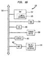
- Figure 1b is a block diagram of a computer as envisioned by various embodiments of the present invention.
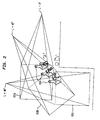
- Figure 2 is a first view of the TEM cell as tilted about an axis through three different angles.
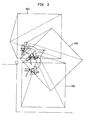
- Figure 3 is a second view of the TEM cell as tilted about an axis through three different angles.
- Figure 4a is a view of the TEM cell depicting various features as contemplated by embodiments of the present invention and environments thereof.
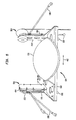
- Figure 4b is a general depiction of the fixed tilt mechanism as contemplated by various embodiments of the present invention.
- Figure 5 is a view depicting various features of the fixed tilt mechanism as contemplated by various embodiments of the present invention.
- Figure 6 is a first view of the drive mechanism of the fixed tilt mechanism as contemplated by various embodiments of the present invention.
- Figure 7 is a second view of the drive mechanism of the fixed tilt mechanism as contemplated by various embodiments of the present invention.
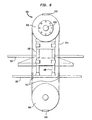
- Figure 8 is a first view of the turn ratio converter of the fixed tilt mechanism as contemplated by various embodiments of the present invention.
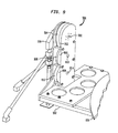
- Figure 9 is a second view of the turn ratio converter of the fixed tilt mechanism as contemplated by various embodiments of the present invention.
- Figure 10 is a flow diagram of a method contemplated by embodiments of the present invention concerning the determination of electric and magnetic fields of the Equipment Under Test.
- Figure 11 depicts a coordinate system for use with various embodiments contemplated by the present invention.
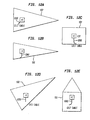
- Figure 12 depicts the effect of the present invention on cabling, as contemplated by first embodiments of the present invention.
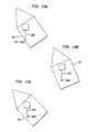
- Figure 13 depicts the effect of the present invention on cabling, as contemplated by second embodiments of the present invention.
- the present invention relates to a system and method for making electromagnetic measurements of a test object (also known as equipment under test (EUT)) using a transverse electromagnetic (TEM) cell. More specifically, the present invention relates to a system and method for maintaining the EUT in a fixed tilt position and, as contemplated by various embodiments, a horizontal (i.e., "gravity-down") position as the TEM cell is tilted and EUT rotated to specified angles. The electromagnetic measurements taken at those angles are then processed to determine the electric field and the magnetic field produced by the EUT.
- a test object also known as equipment under test (EUT)
- TEM transverse electromagnetic
- Embodiments of the present invention contemplate schemes for receiving electromagnetic information from the TEM cell and determining the electric field and magnetic field. The requirements of these schemes (and the various advantages thereof) determine the angles of tilt and rotation of the TEM cell and EUT, respectively. These schemes contemplate that the EUT is maintained in the gravity-down position (or at least in a fixed position relative to the tilt of the TEM cell) during the recording of these readings. Consequently, the present invention also contemplates a fixed tilt mechanism for maintaining the EUT in a specified fixed position while the TEM cell is tilted to various angles.
- a TEM cell 102 is shown suspended on two supports 112.
- the material of the TEM cell should comprise a good conducting material, so that it can act as a coaxial cable as described above.
- Embodiments of the present invention contemplate that the TEM cell can be suspended by any number of means, including those that would suspend it from the sides and/or the top of the cell. Various different sizes and shapes of the cell are also contemplated, some of which will be discussed below.
- any other electromagnetic test cell using transmission line concepts i.e., other than a TEM cell is also contemplated by the present invention.
- the TEM cell 102 can be tilted (i.e., rotated) about an axis 110.
- the axis 110 is perpendicular to the length of the TEM cell 102.
- the present invention contemplates that the axis can be positioned at any number of angles as well.
- the axis is a horizontal axis (with regard to the ground upon which the TEN cell 102 is positioned), although tilting among multiple axes is also contemplated.
- the fixed tilt mechanism comprises a table 106, support structure 108 and hinges 107.
- the table 106 tilts a corresponding amount about an axis 122 in the opposite direction, thus maintaining a specified fixed position (typically, a "gravity-down" position).
- a specified fixed position typically, a "gravity-down" position.
- Various embodiments of the present invention also contemplate that the table 106 is rotatable about an axis 124.
- the EUT is placed upon table 106.
- the TEM cell is then tilted and the table 106 rotated to various positions as will be described further below.
- the electromagnetic energy from the EUT is conducted by the TEM cell 102 down to a wire 114 and into a TEM cell energy interface 116.
- the TEM cell energy interface 116 is some type of mechanism for converting energy in analog form (e.g., voltage) into a digital output that can be interpreted by a digital device.
- the TEM cell energy interface 116 comprises a spectrum analyzer for reading only certain designated frequencies of the received energy. Embodiments of the present invention contemplate that those frequencies selected are the ones having the greatest power level, although other frequencies can be selected for various reasons as well.
- a general purpose instrument bus interface (GPIB) is then used between the spectrum analyzer and the digital device.
- the spectrum analyzer is a model 8568B from Hewlett Packard of Palo Alto, CA, and that the GPIB is a "GPIB-AT" from National Instruments of Austin, TX.
- GPIB General purpose instrument bus interface
- the spectrum analyzer is a model 8568B from Hewlett Packard of Palo Alto, CA, and that the GPIB is a "GPIB-AT" from National Instruments of Austin, TX.
- devices such as RF power meters or RF volt meters could be used in lieu of a spectrum analyzer.
- E and M separator 126 determines how much of the energy received from the TEM is caused by the electric field and how much is caused by the magnetic field of the EUT. It is contemplated that the results are determined as electric and magnetic dipole moments.
- E and M separator contains the set of angles that TEM 102 and table 106 should be tilted and rotated to, respectively. Examples of the E and M separator 126 as contemplated by various embodiments of the present invention will be described further below.
- bus 150 is shown as the backbone connecting various components.
- the bus could use any number of standard architectures, including ISA, EISA, Microchannel, PCMCIA, etc.
- a Random Access Memory (RAM) 152 is shown containing within it the E and M separator 126. It can also contain any electromagnetic information received from TEM cell 102. It should be understood that the RAM could be any other type of memory for storing information, including SRAM, Flash memory, magnetic, optical or atomic memory, or any combination thereof.
- a Read Only Memory (ROM) 154 is also shown, and can also contain E and M separator 126 or portions thereof. ROM 154 can be a conventional ROM, EPROM, EEPROM, etc.
- a Central Processing Unit 156 executes various functions contemplated by embodiments of the present invention (e.g., various aspects of the E and M separator 126).
- the CPU can be any number of CPUs such as a Pentium from Intel Corporation of Santa Clara, CA or 68000 series from Motorola of Schaumburg, I1. It can also be multiple CPUs tied together in a parallel processing configuration.
- Storage device 158 can be any type of mass storage device for storing information, including magnetic, optical or atomic storage devices, and can store all or portions of E and M separator 126 as well as any electromagnetic information received from TEM cell 102. In essence, any information retention device such as the RAM 152, ROM 154 and/or storage device 158 can store all or portions of E and M separator 126 as well as act as a measurement storage mechanism.
- Display 160 can be used for any number of purposes, including reviewing the results of the electric and magnetic field tests in numeric or graphical form, or reviewing the raw results obtained from the TEM 102.
- the display 160 can be any device capable of displaying such information, including a CRT, flat panel display, or even a printer.
- a port 162 is also shown for interfacing the TEM cell energy interface 116 with the rest of computer 120. Thus, the port 162 acts as an information reception mechanism for receiving the electromagnetic measurements.
- computer 120 can comprise any number of different types of computers, including micro, mini, and mainframe.
- present invention also contemplates embodiments where two or more such computers are networked together.
- the TEM cell 102 is shown at three different positions as 102a, 102b and 102c. As can be seen, the TEM cell 102 is pyramidal in shape (which helps reduce unwanted RF reflections), with the fixed tilt mechanism 104 residing inside. It should be noted that the relative size of the fixed tilt mechanism 104 will be determined by a number of factors, including the size of the EUTs that are contemplated to be tested.
- Figure 2 shows how the TEM cell can be tilted to various angles L (about axis 110 as shown in Figure 1a).
- the three angles shown in this example by TEM cells 102a-c are 0, 45 and 90 degrees off the horizontal, respectively.
- any number of different angles are contemplated.
- embodiments of the present invention contemplate that the table portion of fixed tilt mechanism 104 is rotatable about an axis T (corresponding to axis 124 of Figure 1a).
- Figure 3 depicts the tilting motion of TEM cell 102 from a different angle from that shown by Figure 2.
- the tilting of TEM cell 102 is viewed facing the base when the TEM cell 102 is at the various angles 0 - 90 degrees as depicted by TEM cells 102a-c.
- FIG. 4a depicts a top-down view of the TEM cell 102 when no tilting of the TEM cell 102 has occurred (i.e., when the angle is at 0 degrees). That is, the TEM cell 102 is positioned at 0 degrees as shown by TEM cell 102a of Figures 2 and 3, and the view is from looking down through the "top" of the TEM cell 102a. Thus, the surface of the table 106 can be seen. The coordinates X, Y and Z are shown relative to this position of the TEM cell. Note that coordinate "Y" is in a direction passing directly through the top and center of the table 106.
- the TEM cell 102 is tiltable about axis 110, which in these embodiments is shown to be at an angle theta 3 off the centerline 412 of the TEM cell 102.
- theta 3 is 45 degrees. It is desirable that the angle theta 3 (as well as other dimensions of various other aspects of the invention) be set so as to reduce the complexity of ultimately determine the magnetic and electric fields of the EUT.
- Some embodiments of the invention contemplate using a model 1750 TEM cell from EMCO. Of course, the present invention contemplates various other TEM cells as well.
- Some embodiments of the present invention contemplate using an absorber 408.
- the purpose of the absorber 408 is to help prevent unwanted RF reflections.
- the absorber 408 can be effectively used in conjunction with a pyramid-shaped TEM cell 102 mentioned above.
- the ideal test volume for TEM cell 102 is shown as the area within dashed lines 402a, 402b and 402c. This ideal test volume is further positioned within a certain distance from the "top” and “bottom” of the TEM cell 102 of Figure 4a.
- FIG. 4b Some embodiments of the present invention contemplate that the hinges 107 of the fixed tilt mechanism 104 are designed in such a way that the table 106 actually hangs down a certain length from the hinges themselves.
- Figure 4b Such an embodiment is shown by Figure 4b.
- table supports 414 connect the table 106 to the hinges 107.
- Various mechanisms that affect the motion of the table 106 can then be advantageously placed within these table supports 414.
- the table 106 should be placed relatively close to the "base" of the ideal test volume (i.e., it should be placed close to dashed line 402c). Due to the pyramid shape of the ideal test volume, this placement allows larger EUTs to be accurately tested than would otherwise be possible. However, when embodiments such as that depicted by Figure 4b are used, tilting the TEM cell 102 causes the table 106 to fall outside the ideal test volume due to the fact that the table 106 "hangs down" somewhat from the hinges 107 by virtue of the table supports 414.
- the table 106 can shift laterally as the TEM cell 102 is tilted in order to keep the table 106 (and thus, the EUT) within the ideal test volume.
- arrow 410 an example of this lateral movement is depicted by arrow 410.
- the table 106 is "shifted" in a direction parallel to axis 110 in the direction of arrow 410.
- the table 106 is shifted back the other way.
- table 106 is shown as being set atop a cradle 502.
- Table supports 414 are part of the cradle, as shown, and serve to connect the rest of the cradle to support structure 108 in a hinged fashion.
- the cradle 102 can swing movably relative to the support structure 108 via hinges 107 (not shown in this Figure).
- support structure 108 is attached at its base to the "floor" of TEM cell 102 (i.e., the bottom part of the TEM cell 102 when its angle is at 0 degrees).
- FIG. 5 Various embodiments contemplated by the present invention and shown by Figure 5 include a drive mechanism 504 and a turn ratio converter 506.
- the drive mechanism 504 maintains the table 106 in a specified fixed position as the TEM cell 102 is tilted.
- the turn ratio converter 506 can shift the table 106 laterally in the directions shown by arrow 410 (although other directions are also contemplated) to keep the EUT within the ideal test volume, as described above. Embodiments of these two mechanisms 504 and 506 will be described in greater detail below.
- the present invention also contemplates that a motor (not shown) is used to rotate the table 106 to various selected positions.
- FIG 6 is a side view of the drive mechanism 504.
- a top drive wheel 606 is fastened to a drivewheel axle 616, which in turn is fastened to cradle 502 (as will be shown in Figure 7).
- Drivewheel axle 616 is positioned through support structure 108, and is free to rotate about it. Consequently, rotation of top drive wheel 606 causes cradle 502 to rotate in a corresponding fashion.
- a drive belt 614 attaches top drive wheel 606 to a bottom drive wheel 608, and clamps 610 prevent the drive belt 614 from slipping as a force is exerted by the drive belt 614 onto the two drive wheels 606 and 608.
- the drive belt 614 passes through the "floor" of the TEM cell 102 via tubes 612.
- bottom drive wheel 608 is fixed in place and does not rotate relative to the tilting of TEM cell 102. Consequently, as the TEM cell 102 is tilted, the cradle 502 is prevented from tilting. In this way, table 106 can maintain its fixed position irrespective of the angle that TEM cell 102 is tilted.
- bottom drive wheel 608 may be rotated somewhat for specific purposes such as initial adjustments.
- drivewheel axle 616 is attached to cradle 502 via an axle attachment 702. In this way, rotation of axle 616 causes rotation of cradle 502.
- drive mechanism 504 shown by Figures 5-7 are by way of example, and that the present invention contemplates any number of mechanisms for maintaining table 106 in a fixed tilt position as the TEM cell 102 is tilted.
- FIG. 8 A portion of the turn ratio converter 506 is shown at Figure 8.
- a sliding tube 802 is envisioned to be attached to table 106 such that by moving the sliding tube 802, the table 106 will also move a corresponding amount.
- One embodiment envisioned for implementing this while also allowing the table 106 to freely rotate is to place table 106 on a movable, wheeled carriage (not shown) which rests on cradle 502. Table 106 is then free to rotate about the wheeled carriage.
- the sliding tube 802 would be attached to the wheeled carriage such that by moving the sliding tube 802, the table 106 would move accordingly in a lateral manner.
- Sliding tube 802 is envisioned to have a hollow threaded core into which a threaded rod 804 can be rotatably inserted.
- a shaft 806 connects the threaded rod 804 with first small pulley wheel 810.
- rotation of the first small pulley wheel 810 causes threaded rod 804 to rotate, causing sliding tube 802 to either be pulled toward first small pulley wheel 810 or pushed away from it, depending upon the direction of rotation and the orientation of the threading on threaded rod 804.
- This rotation pushes or pulls table 106 laterally away from or toward first small pulley wheel 810.
- a first large pulley wheel 808 is attached to first small pulley wheel 810 via a first belt 812. Because of the relative sizes of the two wheels 808 and 810, one revolution of first large pulley wheel 808 results in more than one revolution of first small pulley wheel 810. First large pulley wheel 808 is shown attached to a first pulley axis 814.
- FIG 9 shows an outer side portion of the turn ratio converter 506.
- turn ratio converter 506 can be seen to be affixed to cradle 502.
- a second large pulley wheel 908 is attached to first pulley axis 814 via a second belt 906. Again, because of relative size, one revolution of second large pulley wheel 908 results in more than one revolution of first pulley axis 814, and thus of first large pulley wheel 808.
- Second large pulley wheel 908 is shown attached to a second pulley axis 910.
- a third large pulley wheel 912 is attached to second pulley axis 910 via a third belt 904, with the same result as described above.
- the third large pulley wheel 912 is shown attached to a third pulley axis 902.
- the third pulley axis 902 is attached to support structure 108.
- the third pulley axis 902 causes third large pulley wheel 912 to turn. From the description of the various wheels and belts of turn ratio converter 506 mentioned above, it can be readily appreciated that a turn of the third pulley axis 902 translates into a much more than a single turn of shaft 806 in Figure 8. In this way, tilting TEM cell 102 ultimately results in the lateral movement of table 106.
- the amount of lateral movement that table 106 should be moved due to the tilting of the TEM cell 102 depends on a number of factors, including the size and shape of the ideal test volume, the position of the table 106 within the ideal test volume, and the anticipated size of prospective EUTs. Moreover, it should be understood that the present invention contemplates any number of other configurations for performing the function of the turn ratio converter 506 described above. That is, for example, other combinations of wheels and belts could be used, as well as gears rather than wheels. In general, any device that translates the tilting motion of the TEM cell 102 into a force for laterally moving table 106 as described above can be used.
- the specific angles to which the TEM cell is tilted and table 106 rotated to take the readings for determining the electric and magnetic fields depends upon various factors.
- One example may include the desire to tilt the TEM cell by an amount that lessens the amount that any cables attached to the EUT might otherwise move.
- Another example may include a desire to take relatively few readings and/or simplify the calculations required to calculate the fields.
- it is the scheme for determining the fields from the readings received from the TEM cell that drives the angles that will be used.
- the present invention generally, contemplates a variety of schemes for making such calculations for a TEM cell tilted to two or more different angles.
- Embodiments of a method of operation of the present invention concerning the determination of the electric and magnetic fields (and, particularly, electric and magnetic dipole moments) as contemplated by embodiments of the present invention (and, particularly, embodiments of E and M separator 126) are now shown with regard to the flowchart of Figure 10.
- TEM cell 102 is tilted and table 106 rotated to a designated angle. This is indicated by a block 1002.
- the electromagnetic measurement is then taken from the TEN cell 102 at the above-noted angle and is stored. This is indicated by a block 1004.
- Embodiments of the present invention contemplate that the reading can be stored in at least any of the various storage devices mentioned above with regard to Figure 1b.
- this determination is pre-set, and that a certain number of readings (using a set of tilt and rotation angles) will always be taken. Other embodiments contemplate that this determination is made based upon certain criteria, for example, whether degeneracies are present (as explained below). In any event, if more readings need to be taken, control proceeds with block 1002, and the TEM cell 102 is tilted and table 106 rotated to its next angles.
- the stored information is used to determine the magnetic dipole moments. This is indicated by a block 1010.
- the electric dipole moments are also determined, as indicated by a block 1012.
- ⁇ is defined as the angle between the plane that passes through the center of the ideal test volume and a horizontal line that is perpendicular to the axis of cell rotation 110.
- ⁇ 0° is defined as the position where the plane passing through the center of the ideal test volume is horizontal.
- ⁇ can vary in this example from 0°, when the cell is horizontal, to 90°, when it is vertical.
- T is defined as the turntable position of table 106 in which the EUT +X axis is aligned transverse to the TEM cell 102 (i.e., the EUT +X axis is parallel with the direction of the +X axis as shown in Figure 4a). T can be positioned from 0° to 360°.
- the coordinate system is the one shown and described with regard to Figure 4a.
- v h normalized 2 (P y *cos( ⁇ ) + P x *cos(T + 225°)*sin( ⁇ ) + P z *cos(T + 135°)*sin( ⁇ )) 2 + (k 0 (M y *sin( ⁇ )*cos(45°) + M x *(sin(T+45)/ 2 + cos(T+45) *cos( ⁇ )/ 2 )+ M z *(sin(T-45)/ 2 + cos(T- 45)*cos( ⁇ )/ 2 ))) 2
- the voltage represents the combined effects of the magnetic and electric fields produced by the EUT.
- the present invention must now sort out how much each field contributed to the voltage.
- the voltage is adjusted to take such factors as the size of the TEM cell and the distance for which the fields are being tested.
- the k 0 in the equation refers to a constant known as a "wave number" that varies with the frequencies of the EUT being analyzed.
- Embodiments of the present invention contemplate that a "degeneracy" exists if any reading is less than 10 percent of the largest reading. If this is the case, then one of two approaches must be used.
- the EUT may be reoriented relative to its coordinate system and the readings retaken until a set of readings is found having no degeneracies.
- the other approach is to use the following additional steps.
- the EUT frame of reference is arranged symmetrically around the horizontal plane, as indicated in Figure 11.
- +X, +Y and +Z are arranged symmetrically over horizontal.
- the negative end of the axes are below horizontal.
- the cell may be tilted about an axis which is horizontal and oriented at 45 degrees off of the centerline.
- the EUT may be turned on table 106 in the horizontal plane.
- v h normalized 2 ( P y *(cos( ⁇ ) - 2 *cos(T + 165°)*sin( ⁇ ))/ 3 + ( P x *(cos( ⁇ ) - 2 *cos(T + 45°)*sin( ⁇ ))/ 3 + ( P z *(cos( ⁇ ) - 2 *cos(T + 285°)*sin( ⁇ ))/ 3 ) 2 + (k 0 (M y *(sin(T+165) + sin ( ⁇ )/ 2 + cos(T+165)*cos( ⁇ ))/ 3 + M x *(sin(T+ 45) + sin( ⁇ )/ 2 + cos(T+ 45)*cos( ⁇ ))/ 3 + M z *(sin(T + 285) + sin ( ⁇ ⁇
- the cross terms are treated as separate variables and solved for separately.
- This approach requires taking electromagnetic measurements at 12 positions. While mathematically as few as 6 non-zero readings can be taken (and various embodiments contemplate that approach), taking the measurements at the 12 positions requires that the TEM cell 102 be tilted to a lesser extent, while still allowing accurate readings to be obtained.
- the solution for each variable may be found by expressing the unknown as a fraction of two determinants with the denominator being the determinate of M and the numerator obtained from M by replacing the column of coefficients of the unknown in question by the square of the voltage read at that position.
- the solution for Py would be:
- embodiments of the present invention contemplate that the total radiated power is calculated. This quantity can be used to predict the field strength which will be radiated by the EUT. While many approaches may be taken, one approach is to assume that the radiator is a simple dipole.
- Example 1 and Example 2 can be used to accurately measure frequencies below the 30 MHz level.
- FIG. 12 shows the position of TEM cell 102 from various angles during MEASUREMENTS 1 and 5 of Example 1, in which TEM cell 102 is tilted to 0 degrees and 90 degrees, respectively.
- the designations + or - X, Y and Z represent that portion of the TEM cell 102 that is shown in the designated view.
- the tilt shown by MEASUREMENT 5 assumes that the axis of rotation is 45 degrees off the centerline of the TEM cell 102.
- the position of the cable 1202 is shown in each view for both MEASUREMENTS. As can be seen, there is relatively little motion in the cable as it tilts from 0 to 90 degrees. This is largely due to keeping the relative motion between the connector (e.g., where the cable exits the TEM) and the EUT relatively small.
- this Figure shows the position of TEM cell 102 as TEM cell 102 is tilted to 44.736 degrees, 54.736 degrees and 64.736 degrees, in accordance with Example 2 above. Again, cable 1202 is shown having little relative movement throughout the transition. Here, a large factor is the relatively small degree of tilt of the TEM cell 102 necessitated by these embodiments of the present invention.
Landscapes
- Physics & Mathematics (AREA)
- Electromagnetism (AREA)
- General Physics & Mathematics (AREA)
- Measuring Magnetic Variables (AREA)
- Investigating Or Analysing Biological Materials (AREA)
- Testing Electric Properties And Detecting Electric Faults (AREA)
- Investigating Strength Of Materials By Application Of Mechanical Stress (AREA)
Description
- The present invention relates to a system and method for making electromagnetic measurements of a test object (also known as equipment under test (EUT)) using a transverse electromagnetic (TEM) cell. More specifically, the present invention relates to a system and method for maintaining the EUT in a fixed tilt position and, as contemplated by various embodiments, a horizontal (i.e., "gravity-down") position as the TEM cell is tilted and EUT rotated to specified angles. The electromagnetic readings taken at those angles are then processed to measure the electric field and the magnetic field produced by the EUT.
- Electrical devices such as computers, telephones, etc. all emit a certain amount of electromagnetic radiation, particularly in the radio frequency (RF) portion of the electromagnetic spectrum. More specifically, these devices produce an electric field as well as a magnetic field. Such fields can interfere with the operation of other electrical equipment in the vicinity and, at high enough intensities, can also cause harm to people.
- Because of the unwanted effects of electromagnetic fields, it is important to test electrical devices prior to allowing them to be sold or otherwise used. In fact, many countries require that electrical devices meet certain standards before they can be sold. In the U.S., the Federal Communications Commission sets specific limits concerning the maximum amount of electromagnetic radiation that can be emitted by such devices. These limits can be found in 47 CFR (FCC Rules), Parts 15 and 18.
- Over the years, various schemes and mechanisms have been devised to measure the electromagnetic radiation emanating from electrical devices. One such device developed in recent years uses a large "cell" into which the equipment under test (hereinafter EUT) is placed. The cell acts as a large coaxial cable, with the center wire running through the cell (in the form of a broad flat plate called a "septum") and the outer electrical casing encompassing the EUT. Electromagnetic measurements taken at one end of the cell give an indication of the electromagnetic radiation emitted from the EUT. The emissions from the EUT develop voltages between the cell septum and the outer cell walls. These voltages may be read to determine the magnitude and frequency of the emissions coming from the EUT.
- The "cells" described above are often called Transverse Electromagnetic (TEN) cells. They are referred to as "transverse" because both the electric and magnetic field vectors are everywhere perpendicular to the wave normal. This reproduces the alignment of these fields at large distances from the EUT. TEM cells are described in greater detail in papers such as that written by M. L. Crawford: "Generation of Standard E M Fields Using TEM Transmission Cells," IEEE Transactions on Electromagnetic Compatibility, Vol. EMC-16, No. 4, 1974 p.189-195. Modified TEM cells have been developed which can test for frequencies in the gigahertz range. Such cells include GTEM cells. Other types of cells include WTEM (wire TEM) cells.
- The electromagnetic measurements taken from a TEM cell are a composite of the electric and magnetic fields along two specific vectors. Schemes must thus be devised to analyze this information and separate the electric field reading from the magnetic field reading. Often, electric and magnetic radiators are modeled as being comprised of three mutually orthogonal dipole moments (one corresponding to each of the x, y and z axes). The readings taken are analyzed to solve for these dipole moments of the radiating source.
- In order to get an accurate reading of the electric and magnetic fields, conventional schemes have dictated that the EUT should be rotated and readings taken at various angles and along various axes. This is because TEM cells can only sense electric fields that are vertical and magnetic fields that are horizontal across the TEN cell's width. For example, the electric field of an antenna placed in a horizontal position will not be detected. Consequently, readings of the EUT must be taken at different positions.
- An example of a scheme for analyzing the electromagnetic information taken at various angles and along various axes in a TEM cell has been set forth by Dr. Perry Wilson in "On Simulating OATS Near-Field Emission Measurements Via GTEM Cell Measurements" in the Record of the "1993 IEEE International Symposium on Electromagnetic Compatibility, "August 9- 3, 1993, Dallas, Tx pp 53-57. Dr. Wilson's scheme requires that electromagnetic measurements for 9 different positions of the EUT be taken. His scheme then analyzes the readings and yields three magnetic and three electric dipole moments (one corresponding to each of the x, y and z axes for the electric field and also for the magnetic field). In addition to higher frequencies, this scheme also works for electromagnetic emissions below 30 MHz, which are typically difficult to obtain.
- A problem with Dr. Wilson's scheme is the very fact that it requires turning and tilting the EUT for taking certain readings. Such movements cause wires such as AC power cables (which act as antennas) that may be part of or attached to the EUT to orient themselves differently relative to the rest of the EUT. This movement is a problem, since the wires themselves can be a source of much electromagnetic radiation, and thus typically need to be taken into account when calculating an EUTs electric and magnetic field. If they become reoriented with respect to the EUT during testing, this reorientation will change the electromagnetic field being radiated, causing inaccuracies in the final results.
- One partial solution developed by EMCO of Austin Texas, is to maintain a TEM cell at a tilt angle of 54.736 degrees. Since certain devices such as some printers and medical equipment will simply not work when tilted (which is another problem with schemes that tilt the EUT itself), a rotatable table is inserted into the TEM cell and positioned to maintain the EUT in a horizontal, gravity-down position. EMCO contemplates that the TEM cell can be maintained at this tilt angle and the horizontal table holding the EUT rotated to three different positions to determine the electric and magnetic fields. The scheme for determining the fields assumes a tilt angle of about 54.736 degrees. A discussion describing this can be found in an article by John D. M. Osburn and Edwin L. Bronaugh of EMCO, entitled "The 'Hyper-Rotated' GHz Transverse Electromagnetic (GTEM) Cell, Expanding The Performance Envelope," Euro EMC Conference Proceedings, Sansdowne Exhibition Center, England, 5-9 October, p 2/12-92/12.
- The problem with EMCO's approach is that, particularly where the impedance of the EUT is not already known, it has been determined that the readings obtained from this approach are not always as accurate as desired. This is, at least in part, because the number of viewpoints at which readings are taken is insufficient. In addition, this approach does not work for electromagnetic emissions below 30 MHz. Further, if readings at an angle other than 54.736 degrees were desired, the table used by EMCO would have to be manually readjusted for each angle, and a new scheme for determining the electric and magnetic fields would have to be implemented.
- In an international application published under the Patent Cooperation Treaty (PCT), International Publication Number WO-93/18558, John D. Osburn and Patrick Tomola described a TEM cell with a longitudinal axis positioned at a fixed angle relative to the horizontal. A rotatable table (with axis of rotation parallel to the gravity vector) is positioned inside the cell. Equipment under test is placed on the platform, and by rotating the device through two 120 degree rotations, three mutually orthogonal components of EM emissions are successively measured without tilting the device from its normal, horizontal operating position.
- Thus, what is needed is a scheme for deriving sufficient information from a TEM cell to determine accurate results of the electric and magnetic fields of the EUT so as not to require tilting the EUT. The scheme should permit results to be obtained for "lower" frequencies (e.g., below the 30 MHz level). Further, such a scheme should reduce any reorientation of cables, such as AC power cables or data cables which must exit the cell, from causing errors in the ultimate field readings. If such a scheme necessitates tilting the TEM cell, what is then also needed is a device that maintains the EUT in a fixed tilt position, (e.g., a horizontal or "gravity-down" position) throughout the tilting, thus allowing the automation of the testing procedure.
- The present invention overcomes the deficiencies mentioned above by providing a system and method for maintaining the EUT in a specified, fixed tilt position (i.e., at a fixed angle relative to the ground upon which the TEM cell is positioned), allowing the EUT to rotate while in that specified position and tilting the TEM cell through at least two angles about the EUT. An accurate assessment of the electric and magnetic field generated by the EUT can then be obtained. Specifically, embodiments of the present invention contemplate the use of a fixed tilt mechanism for maintaining the EUT in a fixed position relative to the tilting of the TEM cell. This position is often the gravity-down position (for reasons mentioned above), and embodiments contemplate that the fixed tilt mechanism comprises a rotatable table upon which the EUT can be placed and rotated. In addition, various embodiments also contemplate that the fixed tilt mechanism acts to keep the EUT within a portion of the TEM cell that is favorable for the collection of electromagnetic data, and that the cables attached to the EUT are positioned and connected within the TEM cell in a way that allows their electromagnetic field to be accurately calculated as part of the overall field generated by the EUT.
- The present invention further contemplates various schemes for determining the electric and magnetic fields generated from the EUT based upon the composite electromagnetic reading from the TEM cell. These schemes, which result in improved measurements of the magnetic and electric fields, determine the angles to which the TEM is tilted. (The tilting, consequently, emphasizes the importance of using the fixed tilt mechanism mentioned above.) Thus, the TEM cell is tilted and EUT rotated to specified angles in accordance with these schemes, and electromagnetic measurements are taken at each specified angle. As can be seen, then, these schemes allow the electric and magnetic fields to be determined with a high level of precision and without the need to move the EUT from its specified fixed position.
- Various objects, features, and attendant advantages of the present invention can be more fully appreciated as the same become better understood with reference to the following detailed description of the present invention when considered in connection with the accompanying drawings, in which:
- Figure 1a is a general depiction of various features of embodiments of the present invention and environments thereof.
- Figure 1b is a block diagram of a computer as envisioned by various embodiments of the present invention.
- Figure 2 is a first view of the TEM cell as tilted about an axis through three different angles.
- Figure 3 is a second view of the TEM cell as tilted about an axis through three different angles.
- Figure 4a is a view of the TEM cell depicting various features as contemplated by embodiments of the present invention and environments thereof.
- Figure 4b is a general depiction of the fixed tilt mechanism as contemplated by various embodiments of the present invention.
- Figure 5 is a view depicting various features of the fixed tilt mechanism as contemplated by various embodiments of the present invention.
- Figure 6 is a first view of the drive mechanism of the fixed tilt mechanism as contemplated by various embodiments of the present invention.
- Figure 7 is a second view of the drive mechanism of the fixed tilt mechanism as contemplated by various embodiments of the present invention.
- Figure 8 is a first view of the turn ratio converter of the fixed tilt mechanism as contemplated by various embodiments of the present invention.
- Figure 9 is a second view of the turn ratio converter of the fixed tilt mechanism as contemplated by various embodiments of the present invention.
- Figure 10 is a flow diagram of a method contemplated by embodiments of the present invention concerning the determination of electric and magnetic fields of the Equipment Under Test.
- Figure 11 depicts a coordinate system for use with various embodiments contemplated by the present invention.
- Figure 12 depicts the effect of the present invention on cabling, as contemplated by first embodiments of the present invention.
- Figure 13 depicts the effect of the present invention on cabling, as contemplated by second embodiments of the present invention.
- The present invention relates to a system and method for making electromagnetic measurements of a test object (also known as equipment under test (EUT)) using a transverse electromagnetic (TEM) cell. More specifically, the present invention relates to a system and method for maintaining the EUT in a fixed tilt position and, as contemplated by various embodiments, a horizontal (i.e., "gravity-down") position as the TEM cell is tilted and EUT rotated to specified angles. The electromagnetic measurements taken at those angles are then processed to determine the electric field and the magnetic field produced by the EUT.
- Through the present invention, improved readings of the electromagnetic field of an EUT can be obtained by tilting the TEM cell to at least two different angles and taking electromagnetic measurements at those angles. Embodiments of the present invention contemplate schemes for receiving electromagnetic information from the TEM cell and determining the electric field and magnetic field. The requirements of these schemes (and the various advantages thereof) determine the angles of tilt and rotation of the TEM cell and EUT, respectively. These schemes contemplate that the EUT is maintained in the gravity-down position (or at least in a fixed position relative to the tilt of the TEM cell) during the recording of these readings. Consequently, the present invention also contemplates a fixed tilt mechanism for maintaining the EUT in a specified fixed position while the TEM cell is tilted to various angles.
- General embodiments of the present invention (as well as surrounding environments thereof) are now described with regard to Figure la. Referring to Figure la, a TEM cell 102 is shown suspended on two supports 112. The material of the TEM cell should comprise a good conducting material, so that it can act as a coaxial cable as described above. Embodiments of the present invention contemplate that the TEM cell can be suspended by any number of means, including those that would suspend it from the sides and/or the top of the cell. Various different sizes and shapes of the cell are also contemplated, some of which will be discussed below. Moreover, any other electromagnetic test cell using transmission line concepts (i.e., other than a TEM cell) is also contemplated by the present invention.
- As shown, the TEM cell 102 can be tilted (i.e., rotated) about an axis 110. In this Figure, the axis 110 is perpendicular to the length of the TEM cell 102. However, the present invention contemplates that the axis can be positioned at any number of angles as well. Embodiments of the present invention contemplate that the axis is a horizontal axis (with regard to the ground upon which the TEN cell 102 is positioned), although tilting among multiple axes is also contemplated.
- Within the TEM cell is a fixed tilt mechanism 104. The fixed tilt mechanism comprises a table 106, support structure 108 and hinges 107. When the TEM cell is tilted about axis 110, the table 106 tilts a corresponding amount about an axis 122 in the opposite direction, thus maintaining a specified fixed position (typically, a "gravity-down" position). Various embodiments of the present invention also contemplate that the table 106 is rotatable about an axis 124.
- During the testing of an EUT, the EUT is placed upon table 106. The TEM cell is then tilted and the table 106 rotated to various positions as will be described further below. At each of these positions, embodiments of the present invention contemplate that the electromagnetic energy from the EUT is conducted by the TEM cell 102 down to a wire 114 and into a TEM cell energy interface 116. Basically, it is contemplated that the TEM cell energy interface 116 is some type of mechanism for converting energy in analog form (e.g., voltage) into a digital output that can be interpreted by a digital device.
- Various embodiments of the present invention contemplate that the TEM cell energy interface 116 comprises a spectrum analyzer for reading only certain designated frequencies of the received energy. Embodiments of the present invention contemplate that those frequencies selected are the ones having the greatest power level, although other frequencies can be selected for various reasons as well. A general purpose instrument bus interface (GPIB) is then used between the spectrum analyzer and the digital device. Various embodiments contemplate that the spectrum analyzer is a model 8568B from Hewlett Packard of Palo Alto, CA, and that the GPIB is a "GPIB-AT" from National Instruments of Austin, TX. Of course, any number of other devices from other specific devices could be used as well. In addition, devices such as RF power meters or RF volt meters could be used in lieu of a spectrum analyzer.
- As indicated above, the digitized reading of the energy level received from the TEM is then received via line 118 to a computer 120. An E and M separator 126 then determines how much of the energy received from the TEM is caused by the electric field and how much is caused by the magnetic field of the EUT. It is contemplated that the results are determined as electric and magnetic dipole moments. Embodiments of the present invention contemplate that E and M separator contains the set of angles that TEM 102 and table 106 should be tilted and rotated to, respectively. Examples of the E and M separator 126 as contemplated by various embodiments of the present invention will be described further below.
- An example of computer 120 as contemplated by embodiments of the present invention is shown with regard to Figure 1b. Referring now to Figure 1b, a bus 150 is shown as the backbone connecting various components. The bus could use any number of standard architectures, including ISA, EISA, Microchannel, PCMCIA, etc.
- A Random Access Memory (RAM) 152 is shown containing within it the E and M separator 126. It can also contain any electromagnetic information received from TEM cell 102. It should be understood that the RAM could be any other type of memory for storing information, including SRAM, Flash memory, magnetic, optical or atomic memory, or any combination thereof. A Read Only Memory (ROM) 154 is also shown, and can also contain E and M separator 126 or portions thereof. ROM 154 can be a conventional ROM, EPROM, EEPROM, etc.
- A Central Processing Unit 156 executes various functions contemplated by embodiments of the present invention (e.g., various aspects of the E and M separator 126). The CPU can be any number of CPUs such as a Pentium from Intel Corporation of Santa Clara, CA or 68000 series from Motorola of Schaumburg, I1. It can also be multiple CPUs tied together in a parallel processing configuration.
- Storage device 158 can be any type of mass storage device for storing information, including magnetic, optical or atomic storage devices, and can store all or portions of E and M separator 126 as well as any electromagnetic information received from TEM cell 102. In essence, any information retention device such as the RAM 152, ROM 154 and/or storage device 158 can store all or portions of E and M separator 126 as well as act as a measurement storage mechanism.
- Display 160 can be used for any number of purposes, including reviewing the results of the electric and magnetic field tests in numeric or graphical form, or reviewing the raw results obtained from the TEM 102. The display 160 can be any device capable of displaying such information, including a CRT, flat panel display, or even a printer. A port 162 is also shown for interfacing the TEM cell energy interface 116 with the rest of computer 120. Thus, the port 162 acts as an information reception mechanism for receiving the electromagnetic measurements.
- In general, computer 120 can comprise any number of different types of computers, including micro, mini, and mainframe. In addition, the present invention also contemplates embodiments where two or more such computers are networked together.
- Examples of the configuration and tilting angles of the TEM cell 102 as envisioned by various embodiments of the present invention (and surrounding environments thereof) are now described with regard to Figures 2 and 3. Referring first to Figure 2, the TEM cell 102 is shown at three different positions as 102a, 102b and 102c. As can be seen, the TEM cell 102 is pyramidal in shape (which helps reduce unwanted RF reflections), with the fixed tilt mechanism 104 residing inside. It should be noted that the relative size of the fixed tilt mechanism 104 will be determined by a number of factors, including the size of the EUTs that are contemplated to be tested.
- Regarding the tilting of the TEM cell, Figure 2 shows how the TEM cell can be tilted to various angles L (about axis 110 as shown in Figure 1a). The three angles shown in this example by TEM cells 102a-c are 0, 45 and 90 degrees off the horizontal, respectively. Of course, any number of different angles are contemplated. Also, embodiments of the present invention contemplate that the table portion of fixed tilt mechanism 104 is rotatable about an axis T (corresponding to axis 124 of Figure 1a).
- Figure 3 depicts the tilting motion of TEM cell 102 from a different angle from that shown by Figure 2. Referring to Figure 3, the tilting of TEM cell 102 is viewed facing the base when the TEM cell 102 is at the various angles 0 - 90 degrees as depicted by TEM cells 102a-c.
- Additional and specific descriptions of various embodiments of the present invention (and surrounding environments thereof) are now set forth with regard to Figure 4a. Referring now to Figure 4a, this Figure depicts a top-down view of the TEM cell 102 when no tilting of the TEM cell 102 has occurred (i.e., when the angle is at 0 degrees). That is, the TEM cell 102 is positioned at 0 degrees as shown by TEM cell 102a of Figures 2 and 3, and the view is from looking down through the "top" of the TEM cell 102a. Thus, the surface of the table 106 can be seen. The coordinates X, Y and Z are shown relative to this position of the TEM cell. Note that coordinate "Y" is in a direction passing directly through the top and center of the table 106.
- If the TEM cell 102 were tilted 90 degrees as shown by TEM cell 102 of Figures 2 and 3, then looking through that same part of the TEM cell 102c as was viewed previously (which has now become a "side" of the TEM cell 102 by virtue of the tilting) would reveal only the side of the table 106. This is because the table 106 stayed in the fixed position due to hinges 107, and the TEM cell 102 has tilted about it.
- In the embodiments shown by Figure 4a, the TEM cell 102 is tiltable about axis 110, which in these embodiments is shown to be at an angle theta 3 off the centerline 412 of the TEM cell 102. Various embodiments of the present invention contemplate that theta 3 is 45 degrees. It is desirable that the angle theta 3 (as well as other dimensions of various other aspects of the invention) be set so as to reduce the complexity of ultimately determine the magnetic and electric fields of the EUT. Some embodiments of the invention contemplate using a model 1750 TEM cell from EMCO. Of course, the present invention contemplates various other TEM cells as well.
- Some embodiments of the present invention contemplate using an absorber 408. The purpose of the absorber 408 is to help prevent unwanted RF reflections. The absorber 408 can be effectively used in conjunction with a pyramid-shaped TEM cell 102 mentioned above.
- When using a TEM cell to analyze electromagnetic radiation, it has been found that there is a certain area within the TEM cell 102 that the EUT should remain within for accurate readings to be obtained. The dimensions of this area, often referred to as the "ideal test volume," depend upon a number of factors, including the size and shape of the TEM cell 102 itself. In Figure 4a, the ideal test volume for TEM cell 102 is shown as the area within dashed lines 402a, 402b and 402c. This ideal test volume is further positioned within a certain distance from the "top" and "bottom" of the TEM cell 102 of Figure 4a.
- Some embodiments of the present invention contemplate that the hinges 107 of the fixed tilt mechanism 104 are designed in such a way that the table 106 actually hangs down a certain length from the hinges themselves. Such an embodiment is shown by Figure 4b. Referring to Figure 4b, table supports 414 connect the table 106 to the hinges 107. Various mechanisms that affect the motion of the table 106 can then be advantageously placed within these table supports 414. Some of these mechanisms will be described below.
- Certain embodiments of the present invention contemplate that the table 106 should be placed relatively close to the "base" of the ideal test volume (i.e., it should be placed close to dashed line 402c). Due to the pyramid shape of the ideal test volume, this placement allows larger EUTs to be accurately tested than would otherwise be possible. However, when embodiments such as that depicted by Figure 4b are used, tilting the TEM cell 102 causes the table 106 to fall outside the ideal test volume due to the fact that the table 106 "hangs down" somewhat from the hinges 107 by virtue of the table supports 414.
- To alleviate the problem mentioned above, various embodiments of the present invention provide that the table 106 can shift laterally as the TEM cell 102 is tilted in order to keep the table 106 (and thus, the EUT) within the ideal test volume. Referring back to Figure 4a, an example of this lateral movement is depicted by arrow 410. Specifically, in this embodiment, as the TEM cell is tilted from 0 degrees, the table 106 is "shifted" in a direction parallel to axis 110 in the direction of arrow 410. When the TEM cell 102 is tilted back to 0 degrees, the table 106 is shifted back the other way. Some specific embodiments for implementing this will be described below. Of course, it should be understood that the table 106 can be shifted in any direction in response to the tilting of the TEM cell 102 for any number of reasons, including keeping the table within the ideal test volume. Further, the "shift" need to be entirely lateral.
- Some specific examples of fixed tilt mechanism 104 as contemplated by various embodiments of the present invention are now described with regard to Figures 5-9. Referring first to Figure 5, table 106 is shown as being set atop a cradle 502. Table supports 414 are part of the cradle, as shown, and serve to connect the rest of the cradle to support structure 108 in a hinged fashion. In this way, the cradle 102 can swing movably relative to the support structure 108 via hinges 107 (not shown in this Figure). It is contemplated that support structure 108 is attached at its base to the "floor" of TEM cell 102 (i.e., the bottom part of the TEM cell 102 when its angle is at 0 degrees).
- Various embodiments contemplated by the present invention and shown by Figure 5 include a drive mechanism 504 and a turn ratio converter 506. The drive mechanism 504 maintains the table 106 in a specified fixed position as the TEM cell 102 is tilted. The turn ratio converter 506 can shift the table 106 laterally in the directions shown by arrow 410 (although other directions are also contemplated) to keep the EUT within the ideal test volume, as described above. Embodiments of these two mechanisms 504 and 506 will be described in greater detail below. The present invention also contemplates that a motor (not shown) is used to rotate the table 106 to various selected positions.
- Figure 6 is a side view of the drive mechanism 504. Referring to Figure 6, a top drive wheel 606 is fastened to a drivewheel axle 616, which in turn is fastened to cradle 502 (as will be shown in Figure 7). Drivewheel axle 616 is positioned through support structure 108, and is free to rotate about it. Consequently, rotation of top drive wheel 606 causes cradle 502 to rotate in a corresponding fashion.
- A drive belt 614 attaches top drive wheel 606 to a bottom drive wheel 608, and clamps 610 prevent the drive belt 614 from slipping as a force is exerted by the drive belt 614 onto the two drive wheels 606 and 608. As can be seen, the drive belt 614 passes through the "floor" of the TEM cell 102 via tubes 612. Embodiments of the present invention contemplate that bottom drive wheel 608 is fixed in place and does not rotate relative to the tilting of TEM cell 102. Consequently, as the TEM cell 102 is tilted, the cradle 502 is prevented from tilting. In this way, table 106 can maintain its fixed position irrespective of the angle that TEM cell 102 is tilted. Of course, it should be understood that bottom drive wheel 608 may be rotated somewhat for specific purposes such as initial adjustments.
- Another view of drive mechanism 504 is shown in Figure 7. Referring now to Figure 7, drivewheel axle 616 is attached to cradle 502 via an axle attachment 702. In this way, rotation of axle 616 causes rotation of cradle 502.
- Of course, it should be understood that the embodiments of drive mechanism 504 shown by Figures 5-7 are by way of example, and that the present invention contemplates any number of mechanisms for maintaining table 106 in a fixed tilt position as the TEM cell 102 is tilted.
- A portion of the turn ratio converter 506 is shown at Figure 8. Referring to Figure 8, a sliding tube 802 is envisioned to be attached to table 106 such that by moving the sliding tube 802, the table 106 will also move a corresponding amount. One embodiment envisioned for implementing this while also allowing the table 106 to freely rotate is to place table 106 on a movable, wheeled carriage (not shown) which rests on cradle 502. Table 106 is then free to rotate about the wheeled carriage. The sliding tube 802 would be attached to the wheeled carriage such that by moving the sliding tube 802, the table 106 would move accordingly in a lateral manner.
- Sliding tube 802 is envisioned to have a hollow threaded core into which a threaded rod 804 can be rotatably inserted. A shaft 806 connects the threaded rod 804 with first small pulley wheel 810. Thus, rotation of the first small pulley wheel 810 causes threaded rod 804 to rotate, causing sliding tube 802 to either be pulled toward first small pulley wheel 810 or pushed away from it, depending upon the direction of rotation and the orientation of the threading on threaded rod 804. This rotation, in turn, pushes or pulls table 106 laterally away from or toward first small pulley wheel 810.
- A first large pulley wheel 808 is attached to first small pulley wheel 810 via a first belt 812. Because of the relative sizes of the two wheels 808 and 810, one revolution of first large pulley wheel 808 results in more than one revolution of first small pulley wheel 810. First large pulley wheel 808 is shown attached to a first pulley axis 814.
- Figure 9 shows an outer side portion of the turn ratio converter 506. Referring now to Figure 9, turn ratio converter 506 can be seen to be affixed to cradle 502. As can also be seen, a second large pulley wheel 908 is attached to first pulley axis 814 via a second belt 906. Again, because of relative size, one revolution of second large pulley wheel 908 results in more than one revolution of first pulley axis 814, and thus of first large pulley wheel 808. Second large pulley wheel 908 is shown attached to a second pulley axis 910.
- Lastly, a third large pulley wheel 912 is attached to second pulley axis 910 via a third belt 904, with the same result as described above. The third large pulley wheel 912 is shown attached to a third pulley axis 902.
- The third pulley axis 902 is attached to support structure 108. Thus, when the TEM cell 102 is tilted and the support structure 108 effectively rotates about cradle 502 due to drive mechanism 504 (which keeps the cradle 502 in the fixed position), the third pulley axis 902 causes third large pulley wheel 912 to turn. From the description of the various wheels and belts of turn ratio converter 506 mentioned above, it can be readily appreciated that a turn of the third pulley axis 902 translates into a much more than a single turn of shaft 806 in Figure 8. In this way, tilting TEM cell 102 ultimately results in the lateral movement of table 106.
- The amount of lateral movement that table 106 should be moved due to the tilting of the TEM cell 102 depends on a number of factors, including the size and shape of the ideal test volume, the position of the table 106 within the ideal test volume, and the anticipated size of prospective EUTs. Moreover, it should be understood that the present invention contemplates any number of other configurations for performing the function of the turn ratio converter 506 described above. That is, for example, other combinations of wheels and belts could be used, as well as gears rather than wheels. In general, any device that translates the tilting motion of the TEM cell 102 into a force for laterally moving table 106 as described above can be used.
- The specific angles to which the TEM cell is tilted and table 106 rotated to take the readings for determining the electric and magnetic fields depends upon various factors. One example may include the desire to tilt the TEM cell by an amount that lessens the amount that any cables attached to the EUT might otherwise move. Another example may include a desire to take relatively few readings and/or simplify the calculations required to calculate the fields. In any event, it is the scheme for determining the fields from the readings received from the TEM cell that drives the angles that will be used. The present invention, generally, contemplates a variety of schemes for making such calculations for a TEM cell tilted to two or more different angles.
- Embodiments of a method of operation of the present invention concerning the determination of the electric and magnetic fields (and, particularly, electric and magnetic dipole moments) as contemplated by embodiments of the present invention (and, particularly, embodiments of E and M separator 126) are now shown with regard to the flowchart of Figure 10. Referring now to Figure 10, TEM cell 102 is tilted and table 106 rotated to a designated angle. This is indicated by a block 1002.
- The electromagnetic measurement is then taken from the TEN cell 102 at the above-noted angle and is stored. This is indicated by a block 1004. Embodiments of the present invention contemplate that the reading can be stored in at least any of the various storage devices mentioned above with regard to Figure 1b.
- A determination is then made as to whether more readings need to be taken. This is indicated by decision block 1006. Various embodiments of the present invention contemplate that this determination is pre-set, and that a certain number of readings (using a set of tilt and rotation angles) will always be taken. Other embodiments contemplate that this determination is made based upon certain criteria, for example, whether degeneracies are present (as explained below). In any event, if more readings need to be taken, control proceeds with block 1002, and the TEM cell 102 is tilted and table 106 rotated to its next angles.
- If no more readings are needed, then the stored information is used to determine the magnetic dipole moments. This is indicated by a block 1010. The electric dipole moments are also determined, as indicated by a block 1012.
- Two specific examples of schemes (i.e., examples of embodiments of E and M separator 126 as shown in Figure la) for calculating the electric and magnetic fields as contemplated by embodiments of the present invention are now described. In these two examples, the electric and magnetic dipole moments along the x, y and z axis are solved for. It should be understood, however, that the present invention also contemplates calculation of the magnetic and electric fields with respect to other coordinate systems as well.
- The first example is now described. λ is defined as the angle between the plane that passes through the center of the ideal test volume and a horizontal line that is perpendicular to the axis of cell rotation 110. λ = 0° is defined as the position where the plane passing through the center of the ideal test volume is horizontal. λ can vary in this example from 0°, when the cell is horizontal, to 90°, when it is vertical. T is defined as the turntable position of table 106 in which the EUT +X axis is aligned transverse to the TEM cell 102 (i.e., the EUT +X axis is parallel with the direction of the +X axis as shown in Figure 4a). T can be positioned from 0° to 360°. Thus, the coordinate system is the one shown and described with regard to Figure 4a.
- It can be shown that the equation for measured voltage at the TEM cell (e.g., the voltage received from wire 114 as shown in Figure 1a) is:
- Note that the voltage represents the combined effects of the magnetic and electric fields produced by the EUT. Thus, the present invention must now sort out how much each field contributed to the voltage. By "normalized" in vh normalized, the voltage is adjusted to take such factors as the size of the TEM cell and the distance for which the fields are being tested. To help implement this normalization, reference can be made to the National Bureau of Standards technical notes 1013, 1017, 1040 and 1064 from the U.S. Department of Commerce. It should be understood that the present invention also contemplates embodiments where measurements other than voltage, such as "power," could be looked at.
- The k0 in the equation refers to a constant known as a "wave number" that varies with the frequencies of the EUT being analyzed.
- To solve for the three electric dipole moments and three magnetic dipole moments, seven non-zero readings are required. To insure that this condition is met (in the event that degeneracies are encountered as explained below) a set of nine readings will be defined.
- For the following readings of the EUT taken at the angles of the TEM 102 and table 106 set forth below, the generalized voltage equation given above reduces to the following:
- MEASUREMENT 1 : λ = 0° and T = 0°
- MEASUREMENT 2 : λ = 0° and T = 90°
- MEASUREMENT 3 : λ = 0° and T = +45°
- MEASUREMENT 4 : λ = 0° and T = -45°
- MEASUREMENT 5 : λ = 90° and T = +135°
- MEASUREMENT 6 : λ = 90° and T = -45°
- MEASUREMENT 7 : λ = 90° and T = -135°
- MEASUREMENT 8 : λ = 90° and T = +45°
- MEASUREMENT 9 : λ = 45° and T = +9.74°

-
- Which for the case of Mz and Mx → 0 reduces to:
- From these readings, solutions may be derived for the six dipole moments in the following manner, using 7 of the readings obtained above:
- Disallowing degeneracies, the magnetic dipole moments can be derived as follows:
- The electric dipole moments can then be solved for as follows:
- The solution presented about requires that no degeneracies are present (i.e., none of the readings tend to zero as compared with the other readings). Embodiments of the present invention contemplate that a "degeneracy" exists if any reading is less than 10 percent of the largest reading. If this is the case, then one of two approaches must be used. The EUT may be reoriented relative to its coordinate system and the readings retaken until a set of readings is found having no degeneracies. The other approach is to use the following additional steps.
- As an example, if D1 is degenerate, then one of three cases must exist:
- 1. Mx << Maximum.
- 2. Mz << Maximum.
- 3. Mx and Mz << Maximum. By forming the difference
- 1. If the difference → 0 then both Mx and Mz are small.
- 2. If the difference < 0 then Mx is small and -k0 2*Mz 2 ≈ S1 - S2.
- 3. If the difference > 0 then Mz is small and k0 2*Mx 2 ≈ S1 - S2.
-
- Various embodiments of the first example mentioned above also contemplate a scheme requiring utilization of only 6 measurements (e.g., MEASUREMENTS 3-8). To utilize an example of this implementation, the equation for Py would be substituted with the following:
- The second example contemplated by embodiments of the present invention is now described. In this application, the EUT frame of reference is arranged symmetrically around the horizontal plane, as indicated in Figure 11. In this frame of reference +X, +Y and +Z are arranged symmetrically over horizontal. The negative end of the axes are below horizontal.
- The cell may be tilted about an axis which is horizontal and oriented at 45 degrees off of the centerline. The tilt angle is defined as λ with λ = 0 being when the plane passing through the center of the ideal test volume in the cell is horizontal. The EUT may be turned on table 106 in the horizontal plane. The angle of rotation is T with T = 0 being when the EUT is oriented with Z+ directly over the TEM cell 102 centerline 412.
- With these reference designations, the following equation can be shown to describe the voltage measured at the tip of the TEM cell 102 (e.g., the voltage received from wire 114 as shown in Figure 1a):
- To simplify the matrix operation, the cross terms are treated as separate variables and solved for separately. This approach requires taking electromagnetic measurements at 12 positions. While mathematically as few as 6 non-zero readings can be taken (and various embodiments contemplate that approach), taking the measurements at the 12 positions requires that the TEM cell 102 be tilted to a lesser extent, while still allowing accurate readings to be obtained.
- In choosing a set of measurement points, it must be assured that the resulting readings can be accurately analyzed by the pertinent equations. The equation coefficients, amplitude of the emission and instrumentation sensitivity combine to set a criteria for the minimum spacing which may be used between positions and still yield accurate results. The coefficients for these points are then calculated and placed in a 12x12 matrix. The determinate of the matrix should be evaluated and verified that it is not zero.
An example using the following positions is now shown:λ T 54.736 15 54.736 135 54.736 255 64.736 75 64.736 195 64.736 315 44.736 15 44.736 135 44.736 255 44.736 75 44.736 195 44.736 315 - Calculating the coefficients and fitting them into a matrix, M, results in the following:The determinate is:


- The remaining 5 dipole moments would be calculated in a similar manner.
- Once the 6 dipole moments are computed, embodiments of the present invention contemplate that the total radiated power is calculated. This quantity can be used to predict the field strength which will be radiated by the EUT. While many approaches may be taken, one approach is to assume that the radiator is a simple dipole.
- It should be noted that both Example 1 and Example 2 can be used to accurately measure frequencies below the 30 MHz level.
- Examples of how embodiments of the present invention reduce the effect of reorientation of cables such as AC power cables during testing the EUT is now discussed in conjunction with Examples 1 and 2 above, and with regard to Figures 12 and 13. Referring first to Figure 12, this Figure shows the position of TEM cell 102 from various angles during MEASUREMENTS 1 and 5 of Example 1, in which TEM cell 102 is tilted to 0 degrees and 90 degrees, respectively. The designations + or - X, Y and Z represent that portion of the TEM cell 102 that is shown in the designated view. The tilt shown by MEASUREMENT 5 assumes that the axis of rotation is 45 degrees off the centerline of the TEM cell 102.
- The position of the cable 1202 is shown in each view for both MEASUREMENTS. As can be seen, there is relatively little motion in the cable as it tilts from 0 to 90 degrees. This is largely due to keeping the relative motion between the connector (e.g., where the cable exits the TEM) and the EUT relatively small.
- Referring now to Figure 13, this Figure shows the position of TEM cell 102 as TEM cell 102 is tilted to 44.736 degrees, 54.736 degrees and 64.736 degrees, in accordance with Example 2 above. Again, cable 1202 is shown having little relative movement throughout the transition. Here, a large factor is the relatively small degree of tilt of the TEM cell 102 necessitated by these embodiments of the present invention.
- It should be emphasized that the various components of embodiments of the present invention can be implemented in hardware, software or a combination thereof. In such embodiments, the various components and steps would be implemented in hardware and/or software to perform the functions of the present invention. Any presently available or future developed computer software language and/or hardware components can be employed in such embodiments of the present invention.
- It should also be understood that the present invention is not limited to the embodiments indicated above, and that the examples presented above are merely for the purposes of illustration. The scope of the present invention should therefore be interpreted by the following claims as defined by the forgoing figures and text.
Claims (20)
- A system for obtaining electromagnetic measurements from a test object, comprising:a hollow cell (102) for inserting the test object,said hollow cell comprising an electromagnetically conductive material for conducting electromagnetic radiation generated by the test object, and being tiltable about at least one axis (110), said at least one axis being perpendicular to the direction of the force of gravity; anda table (106) rotatable about its vertical axis (124) within said hollow cell, the test object being positioned upon said table, said system being characterized bya fixed tilt mechanism (104) for maintaining said table in a fixed tilt position relative to said at least one axis as said hollow cell (102) is tilted about said at least one axis (110) perpendicular to the direction of the force of gravity so that the vertical axis (124) remains parallel to the direction of the force of gravity.
- The system of claim 1, wherein said hollow cell (102) is configured in a pyramidal shape, and is a transverse electromagnetic cell.
- The system of claim 1, wherein said hollow cell (102) has a centerline and wherein said axis (110) perpendicular to the direction of the force of gravity is positioned at an angle of 45 degrees relative to said centerline.
- The system of claim 1, wherein said fixed tilt mechanism (104) maintains said table with said vertical axis (124) parallel to the direction of the force of gravity as said hollow cell (102) is tilted about said at least one axis (110) perpendicular to the direction of the force of gravity.
- The system of claim 1, wherein said hollow cell (102) is tiltable between an angle that is 0 degrees relative to said at least one axis (110) perpendicular to the direction of the force of gravity through an angle that is 90 degrees relative to said at least one axis (110) perpendicular to the direction of the force of gravity.
- The system of claim 1, wherein said fixed tilt mechanism (104) comprises:a support structure (108), affixed to and tiltable with the hollow cell, for suspending said table (106) within the hollow cell;a mechanism (107), responsive to the tilted position of said support structure, for maintaining said table in an orientation in which said vertical axis (124) is parallel to the direction of the force of gravity as the hollow cell (102) and said support structure (108) are tilted about the at least one axis (110) perpendicular to the direction of the force of gravity.
- The system of claim 6, further comprising a turn converter (506) for laterally positioning said table (106) relative to said hollow cell (102) in response to the degree of tilt of said support structure (108).
- The system of claim 1, further comprising:an electric component and magnetic component separator (126), for containing a first set of angles at which said hollow cell (102) is to be tilted; anda cell interface (116) for obtaining electromagnetic measurements from the hollow cell, as generated by the test object at said first set of angles;said electric component and magnetic component separator (126) receiving said electromagnetic measurements and determining, using said electromagnetic measurements, the electric field and magnetic field generated by the test object.
- The system of claim 8, wherein said electric component and magnetic component separator (126) comprises a degeneracy detector (156) for detecting degeneracies in said electromagnetic measurements, and for initiating the use of at least one electromagnetic measurement not otherwise required to determine the electric field and magnetic field generated by the test object.
- The system of claim 8, wherein said electric component and magnetic component separator (126) determines said electric field in terms of three electric dipole moments along the x, y and z axes, and determines said magnetic field in terms of three magnetic dipole moments along the x, y and z axes.
- The system of claim 8, wherein said electric component and magnetic component separator (126) comprises a second set of at least two angles at which said table (106) is to be rotated to in conjunction with said first set of at least two angles.
- A method for deriving electromagnetic measurements from a test object within a hollow cell (102), said hollow cell comprising an electromagnetically conductive material for conducting electromagnetic radiation generated by the test object, and being tiltable about at least one axis (110), said at least one axis being perpendicular to the direction of the force of gravity,
and a table (106) rotatable about its vertical axis (124) within said hollow cell (102), and characterized by a fixed tilt mechanism (104) for maintaining said table (106) in a fixed tilt position relative to said at least one axis (110) as said hollow cell (102) is tilted about said at least one axis (110) perpendicular to the direction of the force of gravity so that the vertical axis (124) remains parallel to the direction of the force of gravity, the test object being positioned upon said table (106), the method comprising the steps of :(1) receiving (1004) a first electromagnetic measurement from the cell (102) generated by the test object when the hollow cell (102) is tilted at a first angle;(2) receiving (1004) a second electromagnetic measurement from the cell (102) generated by the test object when the hollow cell (102) is tilted at a second angle;(3) determining (1012) at least one electric dipole moment using said first and second electromagnetic measurements obtained from said steps (1) and (2); and(4) determining (1010) at least one magnetic dipole moment using said first and second electromagnetic measurements obtained from steps 1 and 2. - The method of claim 12, wherein said step (3) comprises the step of determining (1012) three electric dipole moments along the x, y and z axes, and wherein said step (4) comprises the step of determining (1010) three magnetic dipole moments along the x, y and z axes.
- The system of claim 1 further including a cradle (502), upon which said rotatable table (106) rests and which is rotatable relative to said table (106), the axis (110) of rotation of said table being perpendicular to the direction of the force of gravity and the axis (124) of rotation of said cradle being parallel to the direction of the force of gravity.
- The system of claim 14 further including a support structure (108), affixed to and tiltable with the hollow cell (102), for suspending said cradle (502) and said table (106) within the hollow cell (102).
- The system of claim 15 further including a drive mechanism (504), responsive to the tilted position of said support structure (108), for maintaining said cradle (502) and said table (106) in a fixed tilt position as the hollow cell (102) and said support structure (108) are tilted about the at least one axis (110) perpendicular to the direction of the force of gravity.
- The system of claim 16, wherein said drive mechanism (504) comprises a top drive wheel (606) affixed to said cradle (502), wherein said top drive wheel (606) is rotatable relative to said support structure (108), and
wherein said top drive wheel (606) is fixed in place relative to the hollow cell (102), such that said table (106) is maintained in a position wherein its vertical axis (124) is parallel to the direction of the force of gravity. - The system of claim 17, wherein said drive mechanism (504) further comprises a bottom drive wheel (608) positioned outside the hollow cell (102), wherein said bottom drive wheel (608) does not move as a result of the tilting of said cell; anda drive belt (614) for connecting said top drive wheel (606) with said bottom drive wheel (608),said drive belt (614) passing through the surface of the hollow cell (102).
- The system of claim 15, further comprising a turn converter (506) for laterally positioning said table (106) relative to said cradle (502) in response to the degree of tilt of said support structure (108).
- The system of claim 19, further comprising a movable carriage upon which said table (106) rests, wherein said turn converter (506) moves said carriage and said table in response to the degree of tilt of said support structure.
Applications Claiming Priority (3)
| Application Number | Priority Date | Filing Date | Title |
|---|---|---|---|
| US08/321,699 US5589773A (en) | 1994-10-12 | 1994-10-12 | System and method for making electromagnetic measurements using a tiltable transverse electromagnetic cell and a fixed tilt sample holder |
| US321699 | 1994-10-12 | ||
| PCT/US1995/012722 WO1996012198A1 (en) | 1994-10-12 | 1995-10-12 | System and method for making electromagnetic measurements using a transverse electromagnetic cell |
Publications (2)
| Publication Number | Publication Date |
|---|---|
| EP0786094A1 EP0786094A1 (en) | 1997-07-30 |
| EP0786094B1 true EP0786094B1 (en) | 1999-08-04 |
Family
ID=23251661
Family Applications (1)
| Application Number | Title | Priority Date | Filing Date |
|---|---|---|---|
| EP95936245A Expired - Lifetime EP0786094B1 (en) | 1994-10-12 | 1995-10-12 | System and method for making electromagnetic measurements using a transverse electromagnetic cell |
Country Status (5)
| Country | Link |
|---|---|
| US (1) | US5589773A (en) |
| EP (1) | EP0786094B1 (en) |
| JP (1) | JP3219771B2 (en) |
| DE (1) | DE69511278T2 (en) |
| WO (1) | WO1996012198A1 (en) |
Cited By (1)
| Publication number | Priority date | Publication date | Assignee | Title |
|---|---|---|---|---|
| DE10007129A1 (en) * | 2000-02-17 | 2001-09-06 | Univ Hannover | Method and device for determining the vector of a quasi-stationary harmonic vector field |
Families Citing this family (13)
| Publication number | Priority date | Publication date | Assignee | Title |
|---|---|---|---|---|
| KR0137588B1 (en) * | 1994-11-16 | 1998-06-15 | 양승택 | Automatic broadband electromagnetic generator |
| US5754054A (en) * | 1996-06-28 | 1998-05-19 | Siemens Rolm Communications Inc. | Apparatus and method for determining the source and strength of electro-magnetic emissions |
| JPH11281721A (en) * | 1998-03-31 | 1999-10-15 | Advantest Corp | Electromagnetic field measuring method |
| US6249248B1 (en) * | 1998-04-17 | 2001-06-19 | Advantest Corporation | Radio wave visualizing method and apparatus |
| FR2798471B1 (en) * | 1999-09-10 | 2001-11-23 | Inrets | METHOD FOR MEASUREMENT AND DIAGNOSIS OF ELECTROMAGNETIC RADIATION |
| EP1136831A1 (en) * | 2000-03-23 | 2001-09-26 | Siemens Building Technologies AG | Manipulator for devices under test in TEM cells |
| US6626252B1 (en) * | 2002-04-03 | 2003-09-30 | Vector Magnetics Llc | Two solenoid guide system for horizontal boreholes |
| JP4336602B2 (en) * | 2004-03-29 | 2009-09-30 | 津田駒工業株式会社 | Inclined rotary table for machine tools |
| FR2871580B1 (en) * | 2004-06-09 | 2006-10-27 | Inrets | LOCATION OF AN ELECTROMAGNETIC RADIATION SOURCE ON AN ELECTRICAL EQUIPMENT |
| US8412111B2 (en) * | 2005-12-15 | 2013-04-02 | Goldman, Sachs & Co. | Testing voice-based office equipment for immunity to interference from wireless devices |
| US9086432B1 (en) | 2013-06-07 | 2015-07-21 | The Boeing Company | Rapid configuration adapter |
| US10870499B2 (en) * | 2018-10-08 | 2020-12-22 | The Boeing Company | Transverse electromagnetic (TEM) system and method of manufacture |
| WO2021192253A1 (en) * | 2020-03-27 | 2021-09-30 | 三菱電機株式会社 | Appraratus for holding device under test and emc test system |
Family Cites Families (8)
| Publication number | Priority date | Publication date | Assignee | Title |
|---|---|---|---|---|
| SU681364A1 (en) * | 1977-09-02 | 1979-08-25 | Колпинское Отделение Всесоюзного Научно-Исследовательского И Проектно-Конструкторского Института Металлургического Машиностроения Научно-Производственного Объединения Внииметмаш | Scanning device for the eddy-current control of a workpiece of polyhedral cross-section |
| CH670174A5 (en) * | 1986-05-20 | 1989-05-12 | Bbc Brown Boveri & Cie | |
| US5119105A (en) * | 1989-06-23 | 1992-06-02 | Electronic Space Systems Corporation | M&A for performing near field measurements on a dish antenna and for utilizing said measurements to realign dish panels |
| US5126669A (en) * | 1990-11-27 | 1992-06-30 | The United States Of America As Represented By The Administrator, Of The National Aeronautics And Space Administration | Precision measurement of magnetic characteristics of an article with nullification of external magnetic fields |
| US5332463A (en) * | 1992-01-15 | 1994-07-26 | Cray Research, Inc. | Self-aligned sealing fixture for use in assembly of microelectronic packages |
| US5430456A (en) * | 1992-03-13 | 1995-07-04 | The Electro-Mechanics Company | Electromagnetic interference testing apparatus |
| US5316634A (en) * | 1992-06-16 | 1994-05-31 | Life Resonances, Inc. | Portable magnetic field analyzer for sensing ion specific resonant magnetic fields |
| US5404098A (en) * | 1992-08-14 | 1995-04-04 | The Electro-Mechanics Company | Method and apparatus for improved correlation of electromagnetic emmission test data |
-
1994
- 1994-10-12 US US08/321,699 patent/US5589773A/en not_active Expired - Lifetime
-
1995
- 1995-10-12 WO PCT/US1995/012722 patent/WO1996012198A1/en not_active Ceased
- 1995-10-12 EP EP95936245A patent/EP0786094B1/en not_active Expired - Lifetime
- 1995-10-12 DE DE69511278T patent/DE69511278T2/en not_active Expired - Fee Related
- 1995-10-12 JP JP51328296A patent/JP3219771B2/en not_active Expired - Fee Related
Cited By (1)
| Publication number | Priority date | Publication date | Assignee | Title |
|---|---|---|---|---|
| DE10007129A1 (en) * | 2000-02-17 | 2001-09-06 | Univ Hannover | Method and device for determining the vector of a quasi-stationary harmonic vector field |
Also Published As
| Publication number | Publication date |
|---|---|
| JP3219771B2 (en) | 2001-10-15 |
| EP0786094A1 (en) | 1997-07-30 |
| WO1996012198A1 (en) | 1996-04-25 |
| DE69511278D1 (en) | 1999-09-09 |
| JPH10501624A (en) | 1998-02-10 |
| US5589773A (en) | 1996-12-31 |
| DE69511278T2 (en) | 1999-11-25 |
Similar Documents
| Publication | Publication Date | Title |
|---|---|---|
| US5589773A (en) | System and method for making electromagnetic measurements using a tiltable transverse electromagnetic cell and a fixed tilt sample holder | |
| Holloway et al. | Use of reverberation chambers to determine the shielding effectiveness of physically small, electrically large enclosures and cavities | |
| Stenzel et al. | Directional velocity analyzer for measuring electron distribution functions in plasmas | |
| US5430456A (en) | Electromagnetic interference testing apparatus | |
| Massoudi et al. | Long-wavelength electromagnetic power absorption in ellipsoidal model of man and animals | |
| US6795030B2 (en) | Electromagnetic compatibility testing device | |
| Vitale et al. | Gravitational-wave stochastic background detection with resonant-mass detectors | |
| US5754054A (en) | Apparatus and method for determining the source and strength of electro-magnetic emissions | |
| Gekelman et al. | Measurement and instability analysis of three-dimensional anisotropic electron distribution functions | |
| Burton | Critical electron pitch angle anisotropy necessary for chorus generation | |
| Ma et al. | Electromagnetic fields with arbitrary wave impedances generated inside a TEM cell | |
| Lee | An advanced correlation algorithm between GTEM and OATS for radiated emission tests | |
| Podgorski et al. | New concept of emission and susceptibility testing | |
| Loh et al. | A method to minimize emission measurement uncertainty of electrically large EUTs in GTEM cells and FARs above 1 GHz | |
| Dirix et al. | Calculating arbitrarily located sampling data from quiet zone spherical near-field scanning measurements | |
| Berger | A variable position, gravity down G-TEM configuration | |
| CN117347734B (en) | Method for selecting position of special-shaped shielding shell shielding effectiveness test antenna | |
| Freyer et al. | Impact of equipment response characteristics on absorber lined and reverberation chamber test results | |
| Qi et al. | Over the Air Measurement for Wireless Communication Systems | |
| Candidi et al. | Comparison of radiated emission measurements for 500 MHz to 2 GHz in various EMC facilities | |
| Hayakawa et al. | On the system of Aureol-3 satellite direction finding for ionospheric and magnetospheric ELF waves | |
| Wilson et al. | Comparisons of planar versus spherical emission measurements for unintentional emitters | |
| Nothofer et al. | Indirect measurement of field uniformity in TEM cells including cross-polar field components | |
| Bastianelli et al. | Analysis of field probe perturbation in a mode stirred reverberation chamber | |
| Miroshnichenko et al. | Investigation of the resonance field structure in an open resonator by the probe method: Theory and experiment |
Legal Events
| Date | Code | Title | Description |
|---|---|---|---|
| PUAI | Public reference made under article 153(3) epc to a published international application that has entered the european phase |
Free format text: ORIGINAL CODE: 0009012 |
|
| 17P | Request for examination filed |
Effective date: 19970404 |
|
| AK | Designated contracting states |
Kind code of ref document: A1 Designated state(s): DE FR GB IT |
|
| 17Q | First examination report despatched |
Effective date: 19970827 |
|
| GRAG | Despatch of communication of intention to grant |
Free format text: ORIGINAL CODE: EPIDOS AGRA |
|
| GRAG | Despatch of communication of intention to grant |
Free format text: ORIGINAL CODE: EPIDOS AGRA |
|
| GRAH | Despatch of communication of intention to grant a patent |
Free format text: ORIGINAL CODE: EPIDOS IGRA |
|
| GRAH | Despatch of communication of intention to grant a patent |
Free format text: ORIGINAL CODE: EPIDOS IGRA |
|
| GRAA | (expected) grant |
Free format text: ORIGINAL CODE: 0009210 |
|
| AK | Designated contracting states |
Kind code of ref document: B1 Designated state(s): DE FR GB IT |
|
| REF | Corresponds to: |
Ref document number: 69511278 Country of ref document: DE Date of ref document: 19990909 |
|
| ITF | It: translation for a ep patent filed | ||
| ET | Fr: translation filed | ||
| PLBE | No opposition filed within time limit |
Free format text: ORIGINAL CODE: 0009261 |
|
| STAA | Information on the status of an ep patent application or granted ep patent |
Free format text: STATUS: NO OPPOSITION FILED WITHIN TIME LIMIT |
|
| 26N | No opposition filed | ||
| REG | Reference to a national code |
Ref country code: GB Ref legal event code: IF02 |
|
| PGFP | Annual fee paid to national office [announced via postgrant information from national office to epo] |
Ref country code: GB Payment date: 20021010 Year of fee payment: 8 |
|
| PGFP | Annual fee paid to national office [announced via postgrant information from national office to epo] |
Ref country code: FR Payment date: 20021023 Year of fee payment: 8 |
|
| PGFP | Annual fee paid to national office [announced via postgrant information from national office to epo] |
Ref country code: DE Payment date: 20021216 Year of fee payment: 8 |
|
| PG25 | Lapsed in a contracting state [announced via postgrant information from national office to epo] |
Ref country code: GB Free format text: LAPSE BECAUSE OF NON-PAYMENT OF DUE FEES Effective date: 20031012 |
|
| PG25 | Lapsed in a contracting state [announced via postgrant information from national office to epo] |
Ref country code: DE Free format text: LAPSE BECAUSE OF NON-PAYMENT OF DUE FEES Effective date: 20040501 |
|
| GBPC | Gb: european patent ceased through non-payment of renewal fee |
Effective date: 20031012 |
|
| PG25 | Lapsed in a contracting state [announced via postgrant information from national office to epo] |
Ref country code: FR Free format text: LAPSE BECAUSE OF NON-PAYMENT OF DUE FEES Effective date: 20040630 |
|
| REG | Reference to a national code |
Ref country code: FR Ref legal event code: ST |
|
| PG25 | Lapsed in a contracting state [announced via postgrant information from national office to epo] |
Ref country code: IT Free format text: LAPSE BECAUSE OF NON-PAYMENT OF DUE FEES Effective date: 20051012 |