EP0785850B1 - Anaerobic cabinets and systems - Google Patents
Anaerobic cabinets and systems Download PDFInfo
- Publication number
- EP0785850B1 EP0785850B1 EP95933496A EP95933496A EP0785850B1 EP 0785850 B1 EP0785850 B1 EP 0785850B1 EP 95933496 A EP95933496 A EP 95933496A EP 95933496 A EP95933496 A EP 95933496A EP 0785850 B1 EP0785850 B1 EP 0785850B1
- Authority
- EP
- European Patent Office
- Prior art keywords
- cabinet
- access
- anaerobic
- lock
- port
- Prior art date
- Legal status (The legal status is an assumption and is not a legal conclusion. Google has not performed a legal analysis and makes no representation as to the accuracy of the status listed.)
- Expired - Lifetime
Links
- 238000007789 sealing Methods 0.000 claims description 15
- 238000011068 loading method Methods 0.000 claims description 10
- 239000001301 oxygen Substances 0.000 claims description 10
- 229910052760 oxygen Inorganic materials 0.000 claims description 10
- 239000012080 ambient air Substances 0.000 claims description 5
- 230000008020 evaporation Effects 0.000 claims description 5
- 238000001704 evaporation Methods 0.000 claims description 5
- 230000001939 inductive effect Effects 0.000 claims description 4
- 239000007787 solid Substances 0.000 claims description 3
- 238000013022 venting Methods 0.000 claims description 3
- 230000007246 mechanism Effects 0.000 claims description 2
- 238000004804 winding Methods 0.000 claims description 2
- 239000011324 bead Substances 0.000 claims 1
- 239000007789 gas Substances 0.000 description 12
- IJGRMHOSHXDMSA-UHFFFAOYSA-N Atomic nitrogen Chemical compound N#N IJGRMHOSHXDMSA-UHFFFAOYSA-N 0.000 description 11
- QVGXLLKOCUKJST-UHFFFAOYSA-N atomic oxygen Chemical compound [O] QVGXLLKOCUKJST-UHFFFAOYSA-N 0.000 description 6
- 238000009434 installation Methods 0.000 description 6
- 230000008878 coupling Effects 0.000 description 5
- 238000010168 coupling process Methods 0.000 description 5
- 238000005859 coupling reaction Methods 0.000 description 5
- 238000011010 flushing procedure Methods 0.000 description 5
- 229910052757 nitrogen Inorganic materials 0.000 description 5
- 230000015572 biosynthetic process Effects 0.000 description 4
- 238000005755 formation reaction Methods 0.000 description 4
- 239000011261 inert gas Substances 0.000 description 4
- 238000004891 communication Methods 0.000 description 3
- 239000000463 material Substances 0.000 description 3
- 239000000203 mixture Substances 0.000 description 3
- CURLTUGMZLYLDI-UHFFFAOYSA-N Carbon dioxide Chemical compound O=C=O CURLTUGMZLYLDI-UHFFFAOYSA-N 0.000 description 2
- 230000009471 action Effects 0.000 description 2
- 238000009833 condensation Methods 0.000 description 2
- 230000005494 condensation Effects 0.000 description 2
- 238000001125 extrusion Methods 0.000 description 2
- 238000011049 filling Methods 0.000 description 2
- 239000001257 hydrogen Substances 0.000 description 2
- 229910052739 hydrogen Inorganic materials 0.000 description 2
- 230000006872 improvement Effects 0.000 description 2
- 239000007788 liquid Substances 0.000 description 2
- 230000003641 microbiacidal effect Effects 0.000 description 2
- 238000005086 pumping Methods 0.000 description 2
- 238000007363 ring formation reaction Methods 0.000 description 2
- XLYOFNOQVPJJNP-UHFFFAOYSA-N water Substances O XLYOFNOQVPJJNP-UHFFFAOYSA-N 0.000 description 2
- 230000005540 biological transmission Effects 0.000 description 1
- 238000007664 blowing Methods 0.000 description 1
- 229910002092 carbon dioxide Inorganic materials 0.000 description 1
- 239000001569 carbon dioxide Substances 0.000 description 1
- 239000000470 constituent Substances 0.000 description 1
- 238000007865 diluting Methods 0.000 description 1
- 239000013536 elastomeric material Substances 0.000 description 1
- 210000003195 fascia Anatomy 0.000 description 1
- 239000006260 foam Substances 0.000 description 1
- 239000001963 growth medium Substances 0.000 description 1
- 150000002431 hydrogen Chemical class 0.000 description 1
- 238000005470 impregnation Methods 0.000 description 1
- 238000009413 insulation Methods 0.000 description 1
- 230000002452 interceptive effect Effects 0.000 description 1
- 238000011835 investigation Methods 0.000 description 1
- 229940124561 microbicide Drugs 0.000 description 1
- 239000002855 microbicide agent Substances 0.000 description 1
- JCXJVPUVTGWSNB-UHFFFAOYSA-N nitrogen dioxide Inorganic materials O=[N]=O JCXJVPUVTGWSNB-UHFFFAOYSA-N 0.000 description 1
- 239000003566 sealing material Substances 0.000 description 1
- 239000004616 structural foam Substances 0.000 description 1
- 230000009897 systematic effect Effects 0.000 description 1
Images


Classifications
-
- B—PERFORMING OPERATIONS; TRANSPORTING
- B25—HAND TOOLS; PORTABLE POWER-DRIVEN TOOLS; MANIPULATORS
- B25J—MANIPULATORS; CHAMBERS PROVIDED WITH MANIPULATION DEVICES
- B25J21/00—Chambers provided with manipulation devices
- B25J21/02—Glove-boxes, i.e. chambers in which manipulations are performed by the human hands in gloves built into the chamber walls; Gloves therefor
-
- C—CHEMISTRY; METALLURGY
- C12—BIOCHEMISTRY; BEER; SPIRITS; WINE; VINEGAR; MICROBIOLOGY; ENZYMOLOGY; MUTATION OR GENETIC ENGINEERING
- C12M—APPARATUS FOR ENZYMOLOGY OR MICROBIOLOGY; APPARATUS FOR CULTURING MICROORGANISMS FOR PRODUCING BIOMASS, FOR GROWING CELLS OR FOR OBTAINING FERMENTATION OR METABOLIC PRODUCTS, i.e. BIOREACTORS OR FERMENTERS
- C12M41/00—Means for regulation, monitoring, measurement or control, e.g. flow regulation
- C12M41/12—Means for regulation, monitoring, measurement or control, e.g. flow regulation of temperature
- C12M41/14—Incubators; Climatic chambers
-
- C—CHEMISTRY; METALLURGY
- C12—BIOCHEMISTRY; BEER; SPIRITS; WINE; VINEGAR; MICROBIOLOGY; ENZYMOLOGY; MUTATION OR GENETIC ENGINEERING
- C12M—APPARATUS FOR ENZYMOLOGY OR MICROBIOLOGY; APPARATUS FOR CULTURING MICROORGANISMS FOR PRODUCING BIOMASS, FOR GROWING CELLS OR FOR OBTAINING FERMENTATION OR METABOLIC PRODUCTS, i.e. BIOREACTORS OR FERMENTERS
- C12M41/00—Means for regulation, monitoring, measurement or control, e.g. flow regulation
- C12M41/30—Means for regulation, monitoring, measurement or control, e.g. flow regulation of concentration
- C12M41/34—Means for regulation, monitoring, measurement or control, e.g. flow regulation of concentration of gas
Definitions
- This invention relates to anaerobic cabinets and systems such as used or intended for use in microbiology laboratories.
- Requirements for anaerobic cabinets can vary widely according to the amount and types of work to be done at any particular location in relation to anaerobic organisms. It is customary for established manufacturers and suppliers of anaerobic cabinets, such as us, to offer different sizes of cabinets, and appropriate variations of related facilities such as cabinet loading and unloading by way of means individual to each cabinet, also provision of access ports typically in pairs equipped with arm-tubes, whether arm-sealing for bare-hands use or as glove-tubes.
- an anaerobic cabinet or system in which the or each anaerobic cabinet comprises an enclosure with means for providing for all of visibility of its interior from outside, inducing and maintaining prescribed low-oxygen internal atmosphere, controlled lock-type access for manual introduction and removal of items, and hand/arm access port provision for manipulation of said items in the cabinet, the lock-type access including door provisions at least at said port provision affording an in-port chamber for loading and/or unloading appropriate items to and from the chamber through the port/door provisions.
- an anaerobic cabinet or system in which the or each anaerobic cabinet comprises an enclosure with meansfor providing for all of visibility of its interior from outside, inducing and maintaining prescribed low-oxygen internal atmosphere, controlled lock-type access for manual introduction and removal of items, and hand/arm access port provision for manipulation of said items in the cabinet, the lock-type access comprising an access lock unit having first access provisions for said introduction/removal of items and other access provisions capable of individually servicing at least two cabinets each with its own cooperating cabinet access provisions relative to such then shared lock-type access unit.
- Such a system is conveniently implemented as a central or medial lock provision between first and second cabinet extensions to left and right, respectively.
- Access to the system can be from front or rear of the shared or common access lock provision, usually the front, and cabinet access can be through left and right side walls, respectively, of the lock provision.
- Each cabinet provision served by a common access lock provision can have its own atmosphere control system, including for temperature; and such control system could further serve the access lock provision wherever a match is required.
- atmosphere control for each cabinet may be by or from a common control system associated with common access lock provision.
- At least programmed microprocessor provisions will normally be so located.
- even such common control system can usefully allow at least some differences between controlled cabinets, say at least as to temperature, maybe further as to one or more gas components or otherwise as to desired gas mixture.
- an entry/exit lock unit with atmosphere control means operable to achieve desired anaerobic gas conditions (from other conditions including open to ambient), both within itself and further through two selective access means for sealing or communicating separately to either side of the unit.
- Such a lock unit is, of course, consistent with achieving a configuration as for the second aspect, but on a modular basis, namely flanking cabinet units serviced through left and right sides of the lock unit.
- the lock unit can conveniently serving for system loading and unloading at its front, say via an up/down sliding or a door bottom hinged door to open by pulling down, usually to horizontal.
- the cabinet units can typically afford manipulation access by ports with arm-tubes, also from their fronts, and whether as glove-tubes or otherwise to afford a so-called "bare-hands" facility.
- the first aspect of this invention concerns door provisions at said at least one port to afford a small chamber for loading and/or unloading appropriate items to and from the chamber.
- Such port chamber can extend from within an inner door, preferably hinged to open into the chamber, at least to (if not into) an arm-tube holder preferably itself hinged to give access to the port chamber from outside the cabinet.
- Suitable seals for the inner door and/or the arm-tube holder can be as sharp edges onto resilient sealing material, typically registering localised circumscriptions of the door and/or holder, conveniently with closed ring-like seals on the door/holder and triangular generally knife-edge ring formations on opposite sides of cabinet/port walling.
- resilient sealing material typically registering localised circumscriptions of the door and/or holder, conveniently with closed ring-like seals on the door/holder and triangular generally knife-edge ring formations on opposite sides of cabinet/port walling.
- applied pressure in the closed position is preferred, say by way of at least one biassed catch, say as an axially spring-loaded knob on the holder and for turning between engagement and disengagement of a fixed cooperating part associated with cabinet walling.
- applied pressure in the closed position may be applied using a biassed final closure achieving mechanism, say a spring-loaded rotatable shaft carrying a door engager, conveniently with a reciprocal rotation drive externally triggerable to release the inner door by one direction of shaft rotation, conveniently involving (if required) first winding a biassing helical torsion spring to solid (mutual engagement of its turns), and operative automatically to finally close the inner door by the other direction of shaft rotation, conveniently involving a micro-switch after manual inner door movement most of the way to closure.
- At least inner door opening can be by a foot pedal and/or remote wire-less transmission, say of radio or infra red type. At least such inner door opening and pressurised closing provisions constitute another aspect of this invention.
- a satisfactory access regime for such a port chamber may involve atmosphere control provisions specific to the chamber, say for drawing a vaccuum, perhaps further for flushing with inert gas, such as nitrogen, and/or positively filling with anaerobic gas mixture matching contents of the cabinet), and related gas connection(s) thereto.
- inert gas such as nitrogen
- provision is/are for drawing vacuum and for connecting to pressurised inert gas, say nitrogen, conveniently in that order, and whether as a single or repeated two-stage cycle.
- inert gas e.g. nitrogen
- inert gas flushing can usefully involve matching to the cabinet's anaerobic atmosphere, say by pumping therefrom or otherwise taking from supply thereto.
- FIG. 1 Another aspect of this invention generally concerning cabinet ports for manipulation access using arm-tubes concerns the shape or configuration of each such port, which has hitherto having been generally circular, and specifically improvement represented by giving the ports an elongated configuration.
- the port access chamber concerned can be bigger, for example enabling a stack of Petri dishes to be loaded or unloaded at the same time through a vertically elongated port.
- elongation of manipulation access ports can significantly improve ease of working within the cabinet, perhaps particularly for vertical elongation of both of a customary pair of ports equipped with arm-tubes.
- vertically elongated ports can have tops and bottoms curved much as before but with sides only slightly curved, thus to achieve desired improvements and retain capability for use of simple O-ring type seals.
- modularity further permit adjoinment of cabinet units end to end, so that a said access lock unit can be associated with series of two or more cabinet units to either or both sides.
- aperturing provisions in sides of access lock units and in ends of cabinet units can be detailed to permit sealing with through access between cabinets or sealing with selective access between the lock and cabinet units or sealing to close off at either of one side of a lock unit or one end of a cabinet unit, whether using a condensing panel or otherwise.
- a particularly advantageous condensing provision drains condensate to exterior of the cabinet unit and provides for its subsequent evaporation.
- a fan blowing ambient air against external cabinet walling is sufficient to induce adequate condensation internally on that walling, which can advantageously be thin thereat.
- Internal grooved ledging of cabinet walling can be in a V-shape to catch condensate for exit from the cabinet at the downward apex of the V-shape.
- Preferred condensate exit from the cabinet is controlled by a valve opened intermittently, say at regular intervals, such as for about twenty to thirty seconds every half hour or so.
- Suitable condensate evaporation can be by wicking action from a condensate receiver, say through a sheet or pad that could be laid over a support to present a main surface to ambient air, preferably with microbicidal action associated therewith, say as impregnation of wicking material.
- preferred anaerobic cabinets hereof have small internal overpressure compared with external ambient, say up to about 12.5 mm water gauge, which can help use of arm-hole port accessing and/or valved condensate exit. Limiting of such internal overpressure can be by venting through a trap, preferably of suitable oil, advantageously with a non-return valve from the cabinet.
- Another aspect of this invention concerns a basic anaerobic cabinet unit (of a modular system) connectable at either end to any one of at least another similar cabinet unit to operate in a satellite manner, and an access lock unit that may include control provisions for the cabinet unit concerned and other cabinet units, and a condenser panel.
- a basic anaerobic cabinet unit be available as a minimum installation in a form that is usable without an access lock unit of the aforesaid modular system, then with some other access lock provision, which could be a smaller alternative lock provision at and through its end wall, or may well be no more than the port chamber provision(s) indicated above and for either or both of a pair of ports equipped with arm-tubes, then further preferably elongated as also indicated above.
- all control electronics, together with electro-mechanical gas flow pumps and valves will be directly associated with the basic cabinet unit, conveniently in an upper or header box located on and above the usable cabinet enclosure as such.
- basic anaerobic cabinets whether for individual use as a minimum installation or for use in a multi-unit modular system hereof, be similar as to gas etc connections to their usable enclosures, with access thereto in such upper or header boxes. Then, the contents of such boxes will vary according to whether electronic etc control items are local or within a common control as indicated above from a lock unit of a modular system.
- lower and upper cabinet parts i.e. usable or working enclosure and header box
- the front of the lower part sloping upwards and backwards and transparent at least above manipulation access ports, and the upper part sloping forwards and upwards from junction with the lower part to below a narrow front panel that will afford control system inputs/indicators for a minimum installation cabinet.
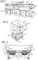
- the lock unit 11 has a front door 13 for loading and unloading items to and from the system 10.
- the door 13 will have convenient provisions for sealing and for opening and closing, which can be of a wholly known and conventional nature as to their detailing. Up/down sliding action is feasible for the door, and may be accompanied by rearward and forward first movements off and onto sealing provisions at start and end of opening and closing movements that are otherwise up and down.
- Upper part 17 of the lock unit 11 is indicated with control panel provisions 19, and will serve to house control system parts that are common to the cabinet units 31L,R to either side. As mentioned above, it is readily made feasible for the control system, such as based on a programmed microprocessor, to control the left and right cabinets differently.
- the lock unit will have suitable opening and sealingly closing communication provisions at both of its sides, i.e. separately relative to both of the cabinets 31L and 31R. Any satisfactory such provisions can be made.
- Figure 2 using primed reference numerals and showing the system access door 13' on an outward porch formation 21, further indicating up/down sliding door systems see door outline indications 23L,R and side slide tracks/frames 25L,R. It will be appreciated that items requiring anaerobic conditions for investigation can go into and out of either of the cabinets 31L,R at will and as desired, including for spending some time in one and other time in the other between loading and unloading to the system 10 as a whole.
- the door provisions (23L,R) of the lock unit 11 will, of course, be operable and normally operated from the cabinets 31L, using its customary access provisions for manipulation, typically using arm-tubes or sleeves connected at ports 33 usually provided in pairs, one for each hand/arm of a technician, and usually of a gloved type (unless a "bare-hands" facility is to be provided.
- Figure 1 indicates such ports 33 in outline manner only (without arm/glove-tubes or sleeves) as holes through front wall 35 of lower part 37 of cabinets 31, but with elongation to aid manipulation via those ports 33. Vertical elongation is shown for both of a pair of ports for both of the cabinets 31L,R.
- FIG 3 shows fitting to manipulation ports, such as outlined at 33 in Figure 1, of an inner door 41 and an outer annular holder 43 for arm-tubes or sleeves (still not shown, but well known as fitting to grooving 43G), each hinged, see 41H and 43H, to open inwards and outwards, respectively, in both cases towards the sides or ends of the cabinets 31, see dashed indications and primed references 41' and 43', It is noted that inner doors 41' then tuck neatly away in the front corners of the cabinets 31, i.e. well clear of interfering with manipulative access through the ports 33 and without obstructing access relative to the lock unit 11 (or any further cabinet unit as will appear below).
- FIG. 4 The elevational view of Figure 4 is from the unhinged side of such port parts 41, 43, but shows greater detail including inner and outer fitting rings 47 and 49 that are fitted securely into front wall aperturing such as 33. Also clearly apparent is the substantial depth of the inner door 41, together with indications 51 of shelf provisions interiorly near top and bottom of the inner door part 41. The depth of the inner door 41 and the extent of the shelf provisions 51 should be consistent with loading Petri dishes of useful size. Elongation of the inner door 41 to match elongation of the ports 33 intendedly to ease/aid manipulation now further serves to improve capacity of the in-port chamber bounded by the shelves 51, say so as to take a stack of Petri dishes. Figure 5 also shows the shelves 51, but omits hinge leaving.
- Figures 6A-D Yet further detail in the effectively exploded view represented by Figures 6A-D, includes protruding ring formations to each side of the fitting rings 47 and 49 to assist in achieving required sealing relative to either side of the front wall 35 on the one hand and with the inner door 41 and the arm-tube holder 43 on the other hand. Also shown are cooperating pairs of hinging leaves 41H' with 41H'' and 43H' with 43H''; along with other side extensions subscripted "E” to cooperate as releasable securements, specifically 41E with 47E and 43E with 49E, and whether of a wholly manual mechanical or at least partly electrical/magnetic and maybe automatic type.
- Figure 6A further shows rounded extension 51E and lipping 51L of the shelves 51 to aid both of item support partly within the arm-tube holder 43 and gripping to swing the inner door 41 back to the aperture 33 whenever so required.
- the inner door 41 will first be loaded with any items to be taken out of the cabinet 31 to ambient and then closed by a technician , in each case using the arm tube of the corresponding holder 43. Then, that holder 43 will be swung away and the bottom one of the shelves 51 will be unloaded (if items are being removed) then loaded with any items to go directly into the cabinet 31 (i.e. rather than go through any lock unit 11).
- the port chamber parts may have at least a vaccuum drawing connection to take most ambient, normally oxygen-rich, atmosphere out of the port chamber. Opening a valve (not shown) from the cabinet, say through the inner door 41, along with normal continuation of anaerobic atmosphere supply to the cabinet 41 could, if there is enough anaerobic gas flow available, flood the port chamber and arm tube, thus producing a very low oxygen content. That low oxygen content could be further diluted by another cycle of vaccuum and flooding from the cabinet; and might be repeated as often as desired or required.
- the arm-tube volume is large compared with empty volume of the port chamber, to provide only one-way valves (specifically from the port chamber to ambient and from the cabinet into the port chamber) and use the arm-tube as a pump, at least if closed off by glove provision.
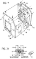
- Figure 1 can be for a purpose-built system of a central lock 11 and flanking cabinets 31L,R, it could equally well represent three units of a modular system (of which the lock of Figure 2 could be one unit). In any event, addition of further cabinet units (like 31) end-to-end with either of the left-hand or right-hand cabinet shown (31L or 31R) would be useful. One way of doing this is indicated in Figure 7 showing another cabinet 31X for adjoinment with the left-hand cabinet 31L of Figure 1 .
- side or end walls 55 of the lower parts 37 of the cabinets 31X and 31L have apertures 57, shown as square (but not necessarily so); and spaced connection bolt holes 59 are shown about them.
- Sealed interconnection or adjoinment is shown provided (see also Figure 7A) by bolts 61 screwing into a frame of structural foam strip 63 shown with an exterior seal 65 as an extrusion of softer elastomeric material conveniently made into an effectively continuous loop and snapped over a key formation 67 of the foam strip 63 (also conveniently an extrusion, of course).
- the seal strip 65 will, of course, be compressed by the side/end walls 55 of the cabinets 31X,L.
- Extra connection bolt provisions are also indicated at 69 for maximising structural integrity and stability.
- unit 71' comprises a flanged frame 72 fitting about aperture 57' in cabinet end wall 55' and carrying a thin plate or sheet 74 with thicker interior insulation 76 at its lower part presenting a V-bottom groove 78 from its upper edge 79 shown defined by further sheet or plate 80.
- a fan 81 fitted (mounting provisions and other details omitted for clarity) to blow ambient air onto an upper part of the sheet or plate 74 and cause condensation on the inner surface of the latter.
- Condensate will collect in the V-grooving 78 for exit through an aperture at its downward apex into a tube part 82A to valve 83 controlling onward flow through tube part 82B to evaporator provision 84.
- the valve is operated by a timer 85 (shown dashed as normally in control electronics) on an intermittent basis, say opened for twenty seconds every half hour (not critical), otherwise closed.
- Suitable evaporation provision is shown by way of condensate receptacle 84 with upstanding inverted-V support 86 for wicking material 87 shown in sheet form laid on the support 86 with its edges to dip into in condensate.
- a microbicide impregnated into the wicking material 87 is preferred. It is further convenient for the condensing unit 71' to house at its lower part within outer grille cover provision 88 a liquid, preferably oil, trap access 89 to ambient.
- This provision is shown as a bottle containing oil 180, and with outlet tube 181 to ambient atmosphere, and inlet tube 182 from the cabinet concerned into the liquid 180 via one-way valve 183, preferably settable or otherwise controllable for opening at a particular overpressure in the cabinet, say about 12 mm water gauge.
- FIG. 9 Particularly preferred opening and closing provisions for the inner port/lock doors 41 is shown in Figure 9, by way of a two-way part-turn-rotational shaft 85 running in bearings 86A, 86B and carrying spaced door engagers 87A and 87B.
- the shaft 85 is shown driven by motor 88 through coupling 89 very much in the manner of a motor windscreen wiper, but with individual control of each direction, say opening on line 90 by a signal from a foot pedal 91 or from a receiver 92 for a remote radio or infra-red transmitter 93, and for final stage of closing by a signal on line 94 from a micro-switch 95 engaged by the door 41 in being partly, preferably mostly, closed manually.
- the drive is shown applied to shaft 85 by a biassing-to-closed provision 96, advantageously two coupling parts 97 and 98 associated irrotationally with the shaft 85 and motor driven shaft 99, respectively.
- Coupling part 97 is shown cup-shaped to house helical torsion spring 101, which acts to apply bias between studs 102 and 103 fixed to the coupling parts 97 and 98, respectively. Opening rotation can include a first part to take up any slack in the spring 101, then drive the shaft 85 with the spring turns touching or solid.
- the motor 88 and its output drive coupling 89 are indicated outside the cabinet, conveniently below, and shaft 89 is shown with a seal 104 and seal clamping holder 105.
- Figure 10 shows a manually operated pressure clamp 110 for the outer doors or arm-tube holders 43.
- This is conveniently of well-known cam-action type acting relative to front provisions of the cabinet, further preferably with sealing provisions 111 .
- Further preferred door or holder 43 seal provisions are indicated by way of circumscribing O-ring 115 in groove 116 and knife edge formation 117 of the cabinet front. Similar interior seal provision for the inner door 41 is also indicated by interior knife edge formation 118.
- modularity of systems hereof is to extend as far as feasible through component parts, for example in avoiding "handing" of items such as the door/tube holder/fitting ring components of the port chambers.
Landscapes
- Chemical & Material Sciences (AREA)
- Engineering & Computer Science (AREA)
- Wood Science & Technology (AREA)
- Zoology (AREA)
- Health & Medical Sciences (AREA)
- Life Sciences & Earth Sciences (AREA)
- Organic Chemistry (AREA)
- Bioinformatics & Cheminformatics (AREA)
- Biomedical Technology (AREA)
- Genetics & Genomics (AREA)
- Biochemistry (AREA)
- Sustainable Development (AREA)
- Analytical Chemistry (AREA)
- Microbiology (AREA)
- Biotechnology (AREA)
- General Engineering & Computer Science (AREA)
- General Health & Medical Sciences (AREA)
- Physics & Mathematics (AREA)
- Thermal Sciences (AREA)
- Robotics (AREA)
- Mechanical Engineering (AREA)
- Manipulator (AREA)
- Accommodation For Nursing Or Treatment Tables (AREA)
- Camera Bodies And Camera Details Or Accessories (AREA)
- Apparatus Associated With Microorganisms And Enzymes (AREA)
Description
Figure 1 indicates
Claims (16)
- Anaerobic cabinet (31) or system (10) in which the or each anaerobic cabinet (31L, R) comprises an enclosure with means for providing for all of visibility (35) of its interior from outside, inducing and maintaining (19, 73) prescribed low-oxygen internal atmosphere, controlled lock-type access (41-43) for manual introduction and removal of items, and hand/arm access port provision (33) for manipulation of said items in the cabinet, characterised by the lock-type access including door provisions (41, 43) at said port provision (33) affording an in-port chamber (41-43) for loading and/or unloading appropriate items to and from the chamber (31L, R) through the port/door provisions (30, 41, 43).
- Anaerobic cabinet or system according to claim 1, wherein the or each said in-port chamber (41-43) extends within an inner door (41) movable in the cabinet (31) out of and back into sealed relation with the cabinet (31), manual access to the cabinet through the in-port chamber (41-43) being via an associated arm-tube holder (43G) itself movable relative to sealing (47, 49) with the cabinet (310 to give access to the in-port chamber (41-43) from outside the cabinet (31).
- Anaerobic cabinet or system according to claim 2, wherein each of said inner door (41) and associated arm-tube holder (43) is hinged (41H, 43H) to the cabinet (31) to open into and away from the cabinet (31), respectively.
- Anaerobic cabinet or system according to claim 3, wherein each of hinged associated inner door (41) and arm-tube holder (43) has biassing (96, 97, 98) into sealing relation with the cabinet (31).
- Anaerobic cabinet or system according to claim 4, wherein the inner door (41) has applied bias pressure in the closed position by a final closure achieving mechanism comprising a spring-loaded (101) reciprocally rotatable shaft (85) carrying a door engager (87A, B) operative to release the inner door (41) by one direction of shaft (85) rotation involving first winding a biassing helical torsion spring (101) to solid, and operative automatically to finally close the inner door (41) by the other direction of shaft (85) rotation on operation of a micro-switch (95) after manual inner door (41) movement towards closure.
- Anaerobic cabinet or system according to any one of claims 2 to 5, wherein seals for each said inner door and each said arm-tube holder involve engagement of sharp edges of respective cabinet beads (117, 118) circumscribing related port aperturing (33) of the cabinet (31) by resilient sealing strips (115) of the door (41) and the holder (43).
- Anaerobic cabinet (31) or system (10) in which the or each anaerobic cabinet (31L, R) comprises an enclosure with means for providing for all of visibility (35) of its interior from outside, inducing and maintaining (19, 73) prescribed low-oxygen internal atmosphere, controlled lock-type access (11, 13) for manual introduction and removal of items, and hand/arm access port provision (33) for manipulation of said items in the cabinet (31), characterised by the lock-type access comprising an access lock unit (11) having first access provisions (13) for said introduction/removal of items and other access provisions (23L, R) capable of individually servicing at least two cabinets (31L, R) each with its own cooperating cabinet access provisions (57) relative to such then shared lock-type access unit (11).
- Anaerobic cabinet system (10) according to claim 7, wherein the access lock unit (11) includes control means (19) operative for establishing and maintaining the same or differing parameters of atmospheres in and for each of said two cabinets (31L, R) sharing the access lock unit (11).
- Anaerobic cabinet system according to claim 7 or claim 8, wherein the access lock unit (11) is between first and second cabinets (31L,R) extending to left and right, respectively, with access to the system through said first the access provision (13) throuh front walling of the then common access lock unit (11) and subsequent cabinet access (23L, R - 57) through corresponding left and right side and end walls of the access lock unit (11) and the cabinets (31L, R), respectively.
- Anaerobic cabinet or system according to any preceding claim, wherein the or each cabinet has side wall provisions (55,57) alternatively accommodating through-access to a or said access lock unit (11) or to another cabinet (31X) or a condensing unit (71) or a blanking plate.
- Anaerobic cabinet or system according to any preceding claim, wherein a or said condensing unit (71) fitting or to fit at or in a side wall (55) of the cabinet (31) comprises a panel (74 - 80) with associated means (81 - 87) for draining condensate to exterior of the cabinet (31) and for its subsequent evaporation.
- Anaerobic cabinet or system according to claim 11, wherein the associated means of the condensing unit (71) includes a fan (81) to blow ambient air against thin walling (74) of the panel, internal grooved ledging (78) of the panel in a V-shape to catch condensate for exit from the cabinet (31) at the downward apex of the V-shape.
- Anaerobic cabinet or system according to claim 11 or claim 12, wherein the associated means of the condensing unit (71) includes a valve (83) opened intermittently to control exit of condensate from the cabinet (31).
- Anaerobic cabinet or system according to claim 11, 12 or 13, wherein the associated means of the condensing unit (71) includes an external condensate receiver (84) and means (87) for wicking condensate for evaporation into ambient air.
- Anaerobic cabinet or system according to any preceding claim, wherein cabinet ports (33) for manipulation access using arm-tubes have an elongated or oval shape or configuration.
- Anaerobic cabinet or system according to any preceding claim, comprising limiting means (89) for desired internal over-pressure by venting from the cabinet (33) through a no-return valve (93) and a trap, preferably of suitable oil (90).
Applications Claiming Priority (5)
| Application Number | Priority Date | Filing Date | Title |
|---|---|---|---|
| GB9420333A GB9420333D0 (en) | 1994-10-08 | 1994-10-08 | Anaerobic cabinets and systems |
| GB9420333 | 1994-10-08 | ||
| GBGB9518485.9A GB9518485D0 (en) | 1995-09-09 | 1995-09-09 | Anaerobic cabinets and systems |
| GB9518485 | 1995-09-09 | ||
| PCT/GB1995/002369 WO1996011092A1 (en) | 1994-10-08 | 1995-10-06 | Anaerobic cabinets and systems |
Publications (2)
| Publication Number | Publication Date |
|---|---|
| EP0785850A1 EP0785850A1 (en) | 1997-07-30 |
| EP0785850B1 true EP0785850B1 (en) | 1998-08-12 |
Family
ID=26305765
Family Applications (1)
| Application Number | Title | Priority Date | Filing Date |
|---|---|---|---|
| EP95933496A Expired - Lifetime EP0785850B1 (en) | 1994-10-08 | 1995-10-06 | Anaerobic cabinets and systems |
Country Status (7)
| Country | Link |
|---|---|
| US (1) | US5861305A (en) |
| EP (1) | EP0785850B1 (en) |
| JP (1) | JPH10507075A (en) |
| AU (1) | AU3613295A (en) |
| DE (1) | DE69504087T2 (en) |
| ES (1) | ES2121416T3 (en) |
| WO (1) | WO1996011092A1 (en) |
Families Citing this family (39)
| Publication number | Priority date | Publication date | Assignee | Title |
|---|---|---|---|---|
| WO1998010054A1 (en) * | 1996-09-09 | 1998-03-12 | Don Whitley Scientific Limited | Controlled atmosphere equipment |
| ATE320217T1 (en) * | 1996-11-18 | 2006-04-15 | Univ Massachusetts | SYSTEMS AND INSTRUMENTS FOR MINIMALLY INVASIVE SURGERY |
| GB9708368D0 (en) * | 1997-04-25 | 1997-06-18 | Whitley Don Scient Ltd | Controlled atmosphere equipment |
| US6013119A (en) * | 1997-05-15 | 2000-01-11 | Genx International, Inc. | Filtering system and method for incubators |
| US6100083A (en) * | 1999-03-16 | 2000-08-08 | Coy Laboratory Products, Inc. | Anaerobic chamber with collapsible diaphragm |
| GB9929415D0 (en) * | 1999-12-14 | 2000-02-09 | Palamatic Handling Syst | Glove box |
| JP4272850B2 (en) * | 2002-06-17 | 2009-06-03 | 学校法人慈恵大学 | Human cell / tissue culture system |
| JP2004236514A (en) * | 2003-02-04 | 2004-08-26 | Hitachi Ltd | Culture device |
| US20040185521A1 (en) * | 2003-03-20 | 2004-09-23 | Shigeru Yoshida | Microorganism sampling method and microorganism sampling device |
| DE10343627B4 (en) * | 2003-09-20 | 2014-03-06 | Eads Deutschland Gmbh | Closure element for an area of the outer skin of an aircraft |
| GB2407048B (en) * | 2003-10-15 | 2007-07-11 | Biotrace Internat Plc | Laboratory apparatus |
| US20050239200A1 (en) * | 2004-04-23 | 2005-10-27 | Beckwith Scott W | Devices for culturing anaerobic microorganisms and methods of using the same |
| JP4570032B2 (en) * | 2004-07-12 | 2010-10-27 | 応用地質株式会社 | Anaerobic culture test apparatus using flexible culture bag |
| DE102004063445A1 (en) * | 2004-12-30 | 2006-07-13 | Hufert, Frank, Prof. Dr. | High security laboratory container module has several insulated, evacuated rooms fitted with shock absorbing system containing interconnected vacuum cabinets which are also fitted with a shock absorbing system |
| US7780248B2 (en) * | 2005-07-19 | 2010-08-24 | Merrick & Company | Glovebox for a double wall containment module |
| US7381127B2 (en) * | 2005-08-12 | 2008-06-03 | Flow Sciences, Inc. | Apparatus for transferring hazardous material |
| GB0521884D0 (en) * | 2005-10-27 | 2005-12-07 | Newcastle Upon Tyne Hospitals | Laboratory apparatus |
| CA2678174A1 (en) * | 2007-02-15 | 2008-08-21 | Robert Stevenson | Methods and cages for screening for infectious agents in laboratory animals |
| FR2920687A1 (en) * | 2007-09-11 | 2009-03-13 | Cogema | DEVICE FOR REDUCING THE ROUND OF LARGE DIAMETER BAGS |
| FR2932702B1 (en) * | 2008-06-19 | 2010-08-27 | Pomagalski Sa | TRANSPORT INSTALLATION BETWEEN TWO ENCLOSURES UNDER CONTROLLED ATMOSPHERE |
| GB0910936D0 (en) | 2009-06-24 | 2009-08-05 | Whitley Don Scient Ltd | User access port for controlled atmosphere apparatus |
| JP5581018B2 (en) * | 2009-07-30 | 2014-08-27 | パナソニックヘルスケア株式会社 | Sterilization cabinet |
| EP2335886B1 (en) * | 2009-12-19 | 2016-08-17 | Harro Höfliger Verpackungsmaschinen GmbH | Assembly for processing materials at risk of contamination |
| US8186775B2 (en) | 2010-05-19 | 2012-05-29 | Sheldon Dan M | Ergonomically improved arm portal and pass box assembly |
| JP5852792B2 (en) * | 2011-04-28 | 2016-02-03 | パナソニックヘルスケアホールディングス株式会社 | Isolator, method of moving culture |
| JP5717774B2 (en) * | 2013-02-04 | 2015-05-13 | パナソニックヘルスケアホールディングス株式会社 | Isolator system |
| JP5717773B2 (en) * | 2013-02-04 | 2015-05-13 | パナソニックヘルスケアホールディングス株式会社 | Sterilizer and isolator system with sterilizer |
| GB2512277B (en) * | 2013-02-19 | 2016-12-14 | Whitley Don Scient Ltd | Controlled atmosphere workstation |
| WO2014156136A1 (en) * | 2013-03-29 | 2014-10-02 | パナソニックヘルスケア株式会社 | Isolator system |
| JP6684573B2 (en) * | 2015-11-13 | 2020-04-22 | オリンパス株式会社 | Cell culture device |
| US10926305B2 (en) * | 2017-08-02 | 2021-02-23 | Marc Cordes | Methods and systems for decontaminating harmful material |
| GB2591613A (en) * | 2018-06-23 | 2021-08-04 | Parambathu Rajesh Panthavoor Chandanam | An enclosure for conducting hot works |
| CN108918852A (en) * | 2018-09-18 | 2018-11-30 | 河南豫乾技术转移中心有限公司 | Quarantine monitoring device equipped with check plot |
| EP3771526B1 (en) * | 2019-07-30 | 2022-11-30 | Skan Ag | Glove device for protected intervention in a containment |
| DK3771525T5 (en) | 2019-07-30 | 2023-01-16 | Skan Ag | Device for protection against unauthorized intervention with a work glove in an enclosure |
| JP7360022B2 (en) * | 2019-08-26 | 2023-10-12 | 澁谷工業株式会社 | Cell processing system |
| US11772581B2 (en) * | 2019-10-03 | 2023-10-03 | Battelle Energy Alliance, Llc | Transfer ports for confinement gloveboxes and related methods |
| CN112111392A (en) * | 2020-10-26 | 2020-12-22 | 贵州中医药大学 | Anaerobic operation box for extracting intestinal flora from excrement |
| CN116215897B (en) * | 2022-12-30 | 2023-12-19 | 中国科学院空间应用工程与技术中心 | A space station online cabinet front panel and online cabinet operation box |
Family Cites Families (15)
| Publication number | Priority date | Publication date | Assignee | Title |
|---|---|---|---|---|
| FR1186485A (en) * | 1957-11-08 | 1959-08-25 | Process and apparatus for isolating a product to be treated from the external atmosphere, before and after treatment | |
| GB1225962A (en) * | 1966-12-16 | 1971-03-24 | ||
| US4111753A (en) * | 1976-06-07 | 1978-09-05 | National Appliance Company | Controlled atmosphere apparatus and method of transferring specimens to same |
| US4262091A (en) * | 1979-04-27 | 1981-04-14 | Anaerobe Systems | Preparation of contaminant free containers of culture medium |
| DE2924446C2 (en) * | 1979-06-18 | 1982-09-16 | W.C. Heraeus Gmbh, 6450 Hanau | Method and device for culturing cells and tissues of humans and animals or of microorganisms |
| GB8411531D0 (en) * | 1984-05-04 | 1984-06-13 | Whitley Don Scient Ltd | Anaerobic conditions |
| GB8510386D0 (en) * | 1985-04-24 | 1985-05-30 | Whitley Scient Ltd Don | Producing anaerobic conditions |
| US4892830A (en) * | 1987-04-02 | 1990-01-09 | Baylor College Of Medicine | Environmentally controlled in vitro incubator |
| GB8916578D0 (en) * | 1989-07-20 | 1989-09-06 | Foster William J | Anaerobic cabinet |
| JP2857209B2 (en) * | 1990-02-23 | 1999-02-17 | タバイエスペック株式会社 | Non-air atmosphere tester |
| JPH03247666A (en) * | 1990-02-26 | 1991-11-05 | Nippon Paint Co Ltd | Colored grain and production thereof |
| US5259812A (en) * | 1992-09-23 | 1993-11-09 | Kleinsek Don A | Clean room and clean room containment center |
| US5257957A (en) * | 1992-10-16 | 1993-11-02 | Diccianni Anthony M | Facility for providing a sealed work area to handle, manipulate and formulate materials |
| US5425400A (en) * | 1993-03-29 | 1995-06-20 | Lee A. Francis | Transfer port apparatus and method |
| FR2713521B1 (en) * | 1993-12-09 | 1996-03-22 | Lenglen Jean Luc | Method and machine for cleaning parts. |
-
1995
- 1995-10-06 DE DE69504087T patent/DE69504087T2/en not_active Expired - Fee Related
- 1995-10-06 JP JP8512422A patent/JPH10507075A/en active Pending
- 1995-10-06 EP EP95933496A patent/EP0785850B1/en not_active Expired - Lifetime
- 1995-10-06 ES ES95933496T patent/ES2121416T3/en not_active Expired - Lifetime
- 1995-10-06 AU AU36132/95A patent/AU3613295A/en not_active Abandoned
- 1995-10-06 US US08/817,324 patent/US5861305A/en not_active Expired - Fee Related
- 1995-10-06 WO PCT/GB1995/002369 patent/WO1996011092A1/en not_active Ceased
Also Published As
| Publication number | Publication date |
|---|---|
| US5861305A (en) | 1999-01-19 |
| EP0785850A1 (en) | 1997-07-30 |
| DE69504087T2 (en) | 1998-12-10 |
| JPH10507075A (en) | 1998-07-14 |
| WO1996011092A1 (en) | 1996-04-18 |
| DE69504087D1 (en) | 1998-09-17 |
| AU3613295A (en) | 1996-05-02 |
| ES2121416T3 (en) | 1998-11-16 |
Similar Documents
| Publication | Publication Date | Title |
|---|---|---|
| US5861305A (en) | Anaerobic cabinets and systems | |
| US4111753A (en) | Controlled atmosphere apparatus and method of transferring specimens to same | |
| US5570628A (en) | Hermetically sealed fresh-keeping container | |
| US5946919A (en) | Food conservator system | |
| US8161768B2 (en) | Modular food preservation system | |
| US6148875A (en) | Vacuum food storage system | |
| CN111380280A (en) | A kind of refrigerator | |
| US20090325275A1 (en) | Cell manipulation and cultivation equipments for the production of cell therapy products | |
| CN1950651B (en) | Vacuum storage compartment construction in cooling apparatus | |
| CA1266224C (en) | Upholstered clean room seat | |
| EP4148363B1 (en) | Refrigerator | |
| US20020025254A1 (en) | Depression container | |
| US20140075889A1 (en) | System and method for storing items | |
| CN115950157B (en) | Refrigeration equipment | |
| JP2025153095A (en) | Electronic balance | |
| US3503703A (en) | Apparatus for sterilizing | |
| CN111998599B (en) | A refrigerator | |
| CN111998593B (en) | A refrigerator | |
| CN210532796U (en) | A kind of refrigerator | |
| CN206062663U (en) | Storage bed | |
| CN113203236B (en) | A kind of refrigerator | |
| GB2276088A (en) | Isolator for laboratory animals | |
| CN112577238B (en) | A refrigerator | |
| CN214357857U (en) | Intelligent vacuum fresh-keeping machine | |
| EP3391795B1 (en) | Compact suction station |
Legal Events
| Date | Code | Title | Description |
|---|---|---|---|
| PUAI | Public reference made under article 153(3) epc to a published international application that has entered the european phase |
Free format text: ORIGINAL CODE: 0009012 |
|
| 17P | Request for examination filed |
Effective date: 19970507 |
|
| AK | Designated contracting states |
Kind code of ref document: A1 Designated state(s): BE CH DE DK ES FR GB IE IT LI NL PT SE |
|
| GRAG | Despatch of communication of intention to grant |
Free format text: ORIGINAL CODE: EPIDOS AGRA |
|
| 17Q | First examination report despatched |
Effective date: 19970919 |
|
| GRAG | Despatch of communication of intention to grant |
Free format text: ORIGINAL CODE: EPIDOS AGRA |
|
| GRAG | Despatch of communication of intention to grant |
Free format text: ORIGINAL CODE: EPIDOS AGRA |
|
| GRAH | Despatch of communication of intention to grant a patent |
Free format text: ORIGINAL CODE: EPIDOS IGRA |
|
| GRAH | Despatch of communication of intention to grant a patent |
Free format text: ORIGINAL CODE: EPIDOS IGRA |
|
| GRAA | (expected) grant |
Free format text: ORIGINAL CODE: 0009210 |
|
| ITF | It: translation for a ep patent filed | ||
| AK | Designated contracting states |
Kind code of ref document: B1 Designated state(s): BE CH DE DK ES FR GB IE IT LI NL PT SE |
|
| PG25 | Lapsed in a contracting state [announced via postgrant information from national office to epo] |
Ref country code: NL Free format text: LAPSE BECAUSE OF FAILURE TO SUBMIT A TRANSLATION OF THE DESCRIPTION OR TO PAY THE FEE WITHIN THE PRESCRIBED TIME-LIMIT Effective date: 19980812 Ref country code: LI Free format text: LAPSE BECAUSE OF FAILURE TO SUBMIT A TRANSLATION OF THE DESCRIPTION OR TO PAY THE FEE WITHIN THE PRESCRIBED TIME-LIMIT Effective date: 19980812 Ref country code: CH Free format text: LAPSE BECAUSE OF FAILURE TO SUBMIT A TRANSLATION OF THE DESCRIPTION OR TO PAY THE FEE WITHIN THE PRESCRIBED TIME-LIMIT Effective date: 19980812 Ref country code: BE Free format text: LAPSE BECAUSE OF FAILURE TO SUBMIT A TRANSLATION OF THE DESCRIPTION OR TO PAY THE FEE WITHIN THE PRESCRIBED TIME-LIMIT Effective date: 19980812 |
|
| REG | Reference to a national code |
Ref country code: CH Ref legal event code: EP |
|
| REF | Corresponds to: |
Ref document number: 69504087 Country of ref document: DE Date of ref document: 19980917 |
|
| PG25 | Lapsed in a contracting state [announced via postgrant information from national office to epo] |
Ref country code: SE Free format text: LAPSE BECAUSE OF FAILURE TO SUBMIT A TRANSLATION OF THE DESCRIPTION OR TO PAY THE FEE WITHIN THE PRESCRIBED TIME-LIMIT Effective date: 19981112 Ref country code: PT Free format text: LAPSE BECAUSE OF FAILURE TO SUBMIT A TRANSLATION OF THE DESCRIPTION OR TO PAY THE FEE WITHIN THE PRESCRIBED TIME-LIMIT Effective date: 19981112 Ref country code: DK Free format text: LAPSE BECAUSE OF FAILURE TO SUBMIT A TRANSLATION OF THE DESCRIPTION OR TO PAY THE FEE WITHIN THE PRESCRIBED TIME-LIMIT Effective date: 19981112 |
|
| REG | Reference to a national code |
Ref country code: ES Ref legal event code: FG2A Ref document number: 2121416 Country of ref document: ES Kind code of ref document: T3 |
|
| REG | Reference to a national code |
Ref country code: IE Ref legal event code: FG4D |
|
| ET | Fr: translation filed | ||
| NLV1 | Nl: lapsed or annulled due to failure to fulfill the requirements of art. 29p and 29m of the patents act | ||
| REG | Reference to a national code |
Ref country code: CH Ref legal event code: PL |
|
| PLBE | No opposition filed within time limit |
Free format text: ORIGINAL CODE: 0009261 |
|
| STAA | Information on the status of an ep patent application or granted ep patent |
Free format text: STATUS: NO OPPOSITION FILED WITHIN TIME LIMIT |
|
| 26N | No opposition filed | ||
| REG | Reference to a national code |
Ref country code: GB Ref legal event code: IF02 |
|
| PGFP | Annual fee paid to national office [announced via postgrant information from national office to epo] |
Ref country code: DE Payment date: 20021004 Year of fee payment: 8 |
|
| PGFP | Annual fee paid to national office [announced via postgrant information from national office to epo] |
Ref country code: IE Payment date: 20021007 Year of fee payment: 8 Ref country code: ES Payment date: 20021007 Year of fee payment: 8 |
|
| PGFP | Annual fee paid to national office [announced via postgrant information from national office to epo] |
Ref country code: FR Payment date: 20021030 Year of fee payment: 8 |
|
| PG25 | Lapsed in a contracting state [announced via postgrant information from national office to epo] |
Ref country code: IE Free format text: LAPSE BECAUSE OF FAILURE TO SUBMIT A TRANSLATION OF THE DESCRIPTION OR TO PAY THE FEE WITHIN THE PRESCRIBED TIME-LIMIT Effective date: 20031006 |
|
| PG25 | Lapsed in a contracting state [announced via postgrant information from national office to epo] |
Ref country code: ES Free format text: LAPSE BECAUSE OF NON-PAYMENT OF DUE FEES Effective date: 20031007 |
|
| PG25 | Lapsed in a contracting state [announced via postgrant information from national office to epo] |
Ref country code: DE Free format text: LAPSE BECAUSE OF NON-PAYMENT OF DUE FEES Effective date: 20040501 |
|
| PG25 | Lapsed in a contracting state [announced via postgrant information from national office to epo] |
Ref country code: FR Free format text: LAPSE BECAUSE OF NON-PAYMENT OF DUE FEES Effective date: 20040630 |
|
| REG | Reference to a national code |
Ref country code: IE Ref legal event code: MM4A |
|
| REG | Reference to a national code |
Ref country code: FR Ref legal event code: ST |
|
| REG | Reference to a national code |
Ref country code: ES Ref legal event code: FD2A Effective date: 20031007 |
|
| PG25 | Lapsed in a contracting state [announced via postgrant information from national office to epo] |
Ref country code: IT Free format text: LAPSE BECAUSE OF NON-PAYMENT OF DUE FEES Effective date: 20051006 |
|
| PGFP | Annual fee paid to national office [announced via postgrant information from national office to epo] |
Ref country code: GB Payment date: 20090304 Year of fee payment: 14 |
|
| PG25 | Lapsed in a contracting state [announced via postgrant information from national office to epo] |
Ref country code: GB Free format text: LAPSE BECAUSE OF NON-PAYMENT OF DUE FEES Effective date: 20091006 |