EP0784714B1 - Low surface energy coatings - Google Patents
Low surface energy coatings Download PDFInfo
- Publication number
- EP0784714B1 EP0784714B1 EP95932855A EP95932855A EP0784714B1 EP 0784714 B1 EP0784714 B1 EP 0784714B1 EP 95932855 A EP95932855 A EP 95932855A EP 95932855 A EP95932855 A EP 95932855A EP 0784714 B1 EP0784714 B1 EP 0784714B1
- Authority
- EP
- European Patent Office
- Prior art keywords
- gas
- chamber
- coating
- plasma source
- lens
- Prior art date
- Legal status (The legal status is an assumption and is not a legal conclusion. Google has not performed a legal analysis and makes no representation as to the accuracy of the status listed.)
- Revoked
Links
- 238000000576 coating method Methods 0.000 title claims abstract description 73
- 239000011248 coating agent Substances 0.000 claims abstract description 59
- 230000003287 optical effect Effects 0.000 claims abstract description 48
- 238000000034 method Methods 0.000 claims abstract description 43
- 239000004215 Carbon black (E152) Substances 0.000 claims abstract description 30
- 229930195733 hydrocarbon Natural products 0.000 claims abstract description 30
- 150000002430 hydrocarbons Chemical class 0.000 claims abstract description 30
- 239000007789 gas Substances 0.000 claims description 60
- VNWKTOKETHGBQD-UHFFFAOYSA-N methane Chemical compound C VNWKTOKETHGBQD-UHFFFAOYSA-N 0.000 claims description 16
- 239000002184 metal Substances 0.000 claims description 14
- XLYOFNOQVPJJNP-UHFFFAOYSA-N water Substances O XLYOFNOQVPJJNP-UHFFFAOYSA-N 0.000 claims description 12
- 230000003213 activating effect Effects 0.000 claims description 9
- 239000000463 material Substances 0.000 claims description 9
- ATUOYWHBWRKTHZ-UHFFFAOYSA-N Propane Chemical compound CCC ATUOYWHBWRKTHZ-UHFFFAOYSA-N 0.000 claims description 8
- QVGXLLKOCUKJST-UHFFFAOYSA-N atomic oxygen Chemical compound [O] QVGXLLKOCUKJST-UHFFFAOYSA-N 0.000 claims description 5
- 239000011261 inert gas Substances 0.000 claims description 5
- 239000001301 oxygen Substances 0.000 claims description 5
- 229910052760 oxygen Inorganic materials 0.000 claims description 5
- 238000010790 dilution Methods 0.000 claims description 4
- 239000012895 dilution Substances 0.000 claims description 4
- 239000001294 propane Substances 0.000 claims description 4
- VZGDMQKNWNREIO-UHFFFAOYSA-N tetrachloromethane Chemical compound ClC(Cl)(Cl)Cl VZGDMQKNWNREIO-UHFFFAOYSA-N 0.000 claims description 4
- XUIMIQQOPSSXEZ-UHFFFAOYSA-N Silicon Chemical compound [Si] XUIMIQQOPSSXEZ-UHFFFAOYSA-N 0.000 claims description 3
- 230000004913 activation Effects 0.000 claims description 3
- 230000006835 compression Effects 0.000 claims description 3
- 238000007906 compression Methods 0.000 claims description 3
- 229910052710 silicon Inorganic materials 0.000 claims description 3
- 239000010703 silicon Substances 0.000 claims description 3
- BOTDANWDWHJENH-UHFFFAOYSA-N Tetraethyl orthosilicate Chemical compound CCO[Si](OCC)(OCC)OCC BOTDANWDWHJENH-UHFFFAOYSA-N 0.000 claims description 2
- 239000012530 fluid Substances 0.000 claims description 2
- 229910052736 halogen Inorganic materials 0.000 claims description 2
- 150000002367 halogens Chemical class 0.000 claims description 2
- UQEAIHBTYFGYIE-UHFFFAOYSA-N hexamethyldisiloxane Chemical compound C[Si](C)(C)O[Si](C)(C)C UQEAIHBTYFGYIE-UHFFFAOYSA-N 0.000 claims description 2
- LFQCEHFDDXELDD-UHFFFAOYSA-N tetramethyl orthosilicate Chemical compound CO[Si](OC)(OC)OC LFQCEHFDDXELDD-UHFFFAOYSA-N 0.000 claims description 2
- 239000002344 surface layer Substances 0.000 claims 1
- 239000000758 substrate Substances 0.000 abstract description 6
- 239000007788 liquid Substances 0.000 description 9
- XKRFYHLGVUSROY-UHFFFAOYSA-N Argon Chemical compound [Ar] XKRFYHLGVUSROY-UHFFFAOYSA-N 0.000 description 6
- IJGRMHOSHXDMSA-UHFFFAOYSA-N Atomic nitrogen Chemical compound N#N IJGRMHOSHXDMSA-UHFFFAOYSA-N 0.000 description 4
- 230000002209 hydrophobic effect Effects 0.000 description 4
- 239000000203 mixture Substances 0.000 description 4
- 238000004544 sputter deposition Methods 0.000 description 4
- 229910052786 argon Inorganic materials 0.000 description 3
- 239000004519 grease Substances 0.000 description 2
- 229910052757 nitrogen Inorganic materials 0.000 description 2
- 238000005268 plasma chemical vapour deposition Methods 0.000 description 2
- OKTJSMMVPCPJKN-UHFFFAOYSA-N Carbon Chemical compound [C] OKTJSMMVPCPJKN-UHFFFAOYSA-N 0.000 description 1
- 229910003481 amorphous carbon Inorganic materials 0.000 description 1
- 239000006117 anti-reflective coating Substances 0.000 description 1
- 230000015572 biosynthetic process Effects 0.000 description 1
- 229910052799 carbon Inorganic materials 0.000 description 1
- 238000005352 clarification Methods 0.000 description 1
- 238000009833 condensation Methods 0.000 description 1
- 230000005494 condensation Effects 0.000 description 1
- 238000007796 conventional method Methods 0.000 description 1
- 238000005336 cracking Methods 0.000 description 1
- 238000000151 deposition Methods 0.000 description 1
- 238000007598 dipping method Methods 0.000 description 1
- 239000000428 dust Substances 0.000 description 1
- 239000001257 hydrogen Substances 0.000 description 1
- 229910052739 hydrogen Inorganic materials 0.000 description 1
- 150000002431 hydrogen Chemical class 0.000 description 1
- 238000011065 in-situ storage Methods 0.000 description 1
- 238000007733 ion plating Methods 0.000 description 1
- 238000010884 ion-beam technique Methods 0.000 description 1
- 229910044991 metal oxide Inorganic materials 0.000 description 1
- 150000004706 metal oxides Chemical class 0.000 description 1
- 238000006263 metalation reaction Methods 0.000 description 1
- 239000002245 particle Substances 0.000 description 1
- 238000000623 plasma-assisted chemical vapour deposition Methods 0.000 description 1
- 229920001296 polysiloxane Polymers 0.000 description 1
- 230000000135 prohibitive effect Effects 0.000 description 1
- 238000000926 separation method Methods 0.000 description 1
- 239000000243 solution Substances 0.000 description 1
- 239000002904 solvent Substances 0.000 description 1
- 239000000126 substance Substances 0.000 description 1
- 239000010409 thin film Substances 0.000 description 1
Images

Classifications
-
- G—PHYSICS
- G02—OPTICS
- G02B—OPTICAL ELEMENTS, SYSTEMS OR APPARATUS
- G02B1/00—Optical elements characterised by the material of which they are made; Optical coatings for optical elements
- G02B1/10—Optical coatings produced by application to, or surface treatment of, optical elements
-
- C—CHEMISTRY; METALLURGY
- C23—COATING METALLIC MATERIAL; COATING MATERIAL WITH METALLIC MATERIAL; CHEMICAL SURFACE TREATMENT; DIFFUSION TREATMENT OF METALLIC MATERIAL; COATING BY VACUUM EVAPORATION, BY SPUTTERING, BY ION IMPLANTATION OR BY CHEMICAL VAPOUR DEPOSITION, IN GENERAL; INHIBITING CORROSION OF METALLIC MATERIAL OR INCRUSTATION IN GENERAL
- C23C—COATING METALLIC MATERIAL; COATING MATERIAL WITH METALLIC MATERIAL; SURFACE TREATMENT OF METALLIC MATERIAL BY DIFFUSION INTO THE SURFACE, BY CHEMICAL CONVERSION OR SUBSTITUTION; COATING BY VACUUM EVAPORATION, BY SPUTTERING, BY ION IMPLANTATION OR BY CHEMICAL VAPOUR DEPOSITION, IN GENERAL
- C23C16/00—Chemical coating by decomposition of gaseous compounds, without leaving reaction products of surface material in the coating, i.e. chemical vapour deposition [CVD] processes
- C23C16/22—Chemical coating by decomposition of gaseous compounds, without leaving reaction products of surface material in the coating, i.e. chemical vapour deposition [CVD] processes characterised by the deposition of inorganic material, other than metallic material
- C23C16/26—Deposition of carbon only
-
- C—CHEMISTRY; METALLURGY
- C23—COATING METALLIC MATERIAL; COATING MATERIAL WITH METALLIC MATERIAL; CHEMICAL SURFACE TREATMENT; DIFFUSION TREATMENT OF METALLIC MATERIAL; COATING BY VACUUM EVAPORATION, BY SPUTTERING, BY ION IMPLANTATION OR BY CHEMICAL VAPOUR DEPOSITION, IN GENERAL; INHIBITING CORROSION OF METALLIC MATERIAL OR INCRUSTATION IN GENERAL
- C23C—COATING METALLIC MATERIAL; COATING MATERIAL WITH METALLIC MATERIAL; SURFACE TREATMENT OF METALLIC MATERIAL BY DIFFUSION INTO THE SURFACE, BY CHEMICAL CONVERSION OR SUBSTITUTION; COATING BY VACUUM EVAPORATION, BY SPUTTERING, BY ION IMPLANTATION OR BY CHEMICAL VAPOUR DEPOSITION, IN GENERAL
- C23C16/00—Chemical coating by decomposition of gaseous compounds, without leaving reaction products of surface material in the coating, i.e. chemical vapour deposition [CVD] processes
- C23C16/22—Chemical coating by decomposition of gaseous compounds, without leaving reaction products of surface material in the coating, i.e. chemical vapour deposition [CVD] processes characterised by the deposition of inorganic material, other than metallic material
- C23C16/30—Deposition of compounds, mixtures or solid solutions, e.g. borides, carbides, nitrides
-
- C—CHEMISTRY; METALLURGY
- C23—COATING METALLIC MATERIAL; COATING MATERIAL WITH METALLIC MATERIAL; CHEMICAL SURFACE TREATMENT; DIFFUSION TREATMENT OF METALLIC MATERIAL; COATING BY VACUUM EVAPORATION, BY SPUTTERING, BY ION IMPLANTATION OR BY CHEMICAL VAPOUR DEPOSITION, IN GENERAL; INHIBITING CORROSION OF METALLIC MATERIAL OR INCRUSTATION IN GENERAL
- C23C—COATING METALLIC MATERIAL; COATING MATERIAL WITH METALLIC MATERIAL; SURFACE TREATMENT OF METALLIC MATERIAL BY DIFFUSION INTO THE SURFACE, BY CHEMICAL CONVERSION OR SUBSTITUTION; COATING BY VACUUM EVAPORATION, BY SPUTTERING, BY ION IMPLANTATION OR BY CHEMICAL VAPOUR DEPOSITION, IN GENERAL
- C23C8/00—Solid state diffusion of only non-metal elements into metallic material surfaces; Chemical surface treatment of metallic material by reaction of the surface with a reactive gas, leaving reaction products of surface material in the coating, e.g. conversion coatings, passivation of metals
- C23C8/06—Solid state diffusion of only non-metal elements into metallic material surfaces; Chemical surface treatment of metallic material by reaction of the surface with a reactive gas, leaving reaction products of surface material in the coating, e.g. conversion coatings, passivation of metals using gases
- C23C8/36—Solid state diffusion of only non-metal elements into metallic material surfaces; Chemical surface treatment of metallic material by reaction of the surface with a reactive gas, leaving reaction products of surface material in the coating, e.g. conversion coatings, passivation of metals using gases using ionised gases, e.g. ionitriding
Definitions
- the present invention relates to a method and apparatus for applying a layer of material to form a low surface energy coating and typically, but not exclusively a coating for a substrate in the form of an optical lens to provide an outer layer having a low surface energy.
- an outer layer of suitable material is required to be applied once the conventional coating processes are completed.
- the desired quality of the outer surface is that it has a low surface energy such that any material or liquids which contact with the surface during use of the lens can be relatively easily removed. If the surface energy of the outer surfaces of the lens is too high then material tends to "stick" to and be attracted to the surface. This tendency to stick causes materials such as liquids or grease to smear when attempts are made to remove the same. Repeated smearing leads to a reduction in the optical quality of the lens and is generally undesirable.
- the recognised method for measuring surface energy is to measure the hydrophobic characteristic of the surface by analysing the contact angle of a drop of pure water on the surface.
- the shape of the water drop and the angle between the surface and the tangent of the water drop is called the contact angle and is related to the surface energy. It is desired that the water contact angle be greater than 70 degrees to be acceptable for optical use. In general, the greater the angle the lower the surface energy.
- the first method requires the lens, once all other coating operations have been completed, to be dipped into a coating mixture and either wiped clean or then placed into an oven where the same are baked, typically for 10 minutes, at a temperature of 50 degrees Celsius.
- This process when the lens are dipped care is required to ensure that the lens are evenly coated with the liquid coating.
- This possibility of uneven coating is exacerbated by the fact that the coating is typically applied by a manual operation, and the time required for the dipping and baking process make this method undesirable to users.
- An alternative method which is known is to prepare a liquid of a composition which, if applied to the lens to provide the outer coating, provides the low surface energy properties required.
- the liquid is applied to the lens when the lens are held within the apparatus in which the previous optical coatings have been applied.
- the liquid is heated externally of the apparatus and the vapour produced passed through supply pipes into the chamber.
- a plasma source in the chamber is operated to crack the vapour into chemical groupings and the required groupings condense on the lens to provide a low surface energy coating.
- the time required for this coating operation is prohibitive as the liquid must first be heated to the required temperature to produce the vapour and the vapour is simultaneously supplied to the chamber.
- DE4211962 discloses a plasma assisted CVD process which uses, preferably microwaves for generating plasma for depositing a low surface energy coating having a thickness of below 20 angstroms or of greater than 100 angstroms on substrates such as headlight reflectors.
- No magnetically enhanced plasma source is disclosed or suggested in this patent and therefore is not applicable to the current use.
- EP0454995 discloses a plasma CVD process for coating ink jet head components with hydrogenated amorphous carbon in thickness of about 1,000 angstroms. Again no magnetically enhanced plasma source is disclosed or suggested.
- WO9213114 discloses a sputtering apparatus for coating lenses comprising at least one magnetron preferably two metal targets in a chamber and a means for reacting the coatings.
- a sputtering apparatus for coating lenses comprising at least one magnetron preferably two metal targets in a chamber and a means for reacting the coatings.
- the aim of the present invention is to provide a method and apparatus for providing a coating with low surface energy properties on optical lens efficiently and as an integral part of an integral part of the lens coating process.
- the present invention provides, in a first aspect a method for forming a low surface energy coating having water contact angle of at least 68° on the surface of an optical lens, said method comprising placing the lens in a chamber, forming a vacuum in the chamber, providing a fluid to the chamber to be introduced into the chamber as a gas containing hydrocarbon groupings and characterised in that the chamber incorporates a magnetically enhanced plasma source which is activated when the gas containing the hydrocarbon groupings is introduced into the chamber to split at least some hydrocarbon groupings from the gas until and at least some of said groupings applied to the surface of the optical lens to produce a low surface energy coating thereon.
- sufficient gas is supplied and hydrocarbon groupings split to provide a coating to a depth of 0.1 - 5 nanometers. A coating of this depth will not substantially affect the optical quality of the lens.
- the plasma source is any of an ion source, plasma source, unbalanced magnetron source or glow discharge means operable by any of d.c., a.c. or r.f. power means, mounted to be operable within the vacuum chamber to split the hydrocarbon groupings from the gas.
- the gas introduced into the chamber is a hydrocarbon such as methane or propane.
- Secondary gases such as hydrogen, argon or oxygen may also be introduced into the chamber along with the hydrocarbon gas.
- the gas is diluted, prior to final compression to atmospheric pressure by the vacuum pumps, in an inert gas such as nitrogen or argon or in air.
- a typical dilution range for methane in air is less than 5% by volume.
- the time taken for application of the outer coating is between 1-5 minutes.
- the low surface energy property of the coating is measured by analysing the hydrophobic characteristics of the same.
- the contact angle of a drop of pure water when methane is used is in the region of 76-90 degrees and 68-72 degrees with propane.
- a method of coating an optical lens comprising the steps of introducing at least one optical lens into a chamber, said chamber containing at least one magnetron with a metal target, and a plasma source, pulling a vacuum in the chamber, activating the magnetron to sputter a metal onto the lens surface, introducing oxygen into the chamber and activating the plasma source to chemically react the metal to provide the required optical coating on the lens, wherein the method comprises the further step of switching off the magnetrons, plasma source and gas supply, introducing a gas containing hydrocarbon groupings into the chamber and activating the plasma source to split at least some hydrocarbon groupings from the gas and deposit the same on the lens to form an outer surface coating having low surface energy characteristics.
- the method includes activating two magnetrons, each having a target of different metal to produce a multilayered optical coating on the lens prior to the introduction of the gas containing hydrocarbon groupings.
- apparatus for the coating of optical lenses comprising a chamber, an optical lens holder within the chamber, a means for pulling a vacuum in the chamber, at least one magnetron with a metal target and a plasma source, drive means for moving optical lens on the holder passed the magnetron and plasma source and control means for activating the magnetron and plasma source, and characterised in that the apparatus further comprises a source for gas containing hydrocarbon groupings and supply means for introducing the gas into the chamber and, when said plasma source is operated when the gas is introduced, to split at least some hydrocarbon groupings from said gas in the chamber.
- the gas source is a conventional gas bottle and the supply means include a control device for controlling the supply of the gas from the bottle into the chamber.
- the control device is, in turn, operated by the control means for the activation of the plasma source and magnetrons.
- the control system is operated by a central computer processor.
- the supply means preferably allow the gas to be diluted in an inert gas such as argon or nitrogen, or in air prior to final compression to atmospheric pressure by the vacuum pumps and the supply means includes a combustible gas sensor, flow meter or other means to monitor the level of dilution.
- an inert gas such as argon or nitrogen
- the gas source and gas supply means can be included for use with conventional optical lens coating apparatus and operation of the same is included as an integral part of the process for providing a complete coating of the optical lens.
- the method of applying an outer coating having low surface energy properties to optical lenses includes the further steps of applying a gas containing groupings other than hydrocarbon groupings to further increase the water contact angle achieved.
- a gas containing groupings other than hydrocarbon groupings to further increase the water contact angle achieved.
- a halogen containing gas such as CF4, C2F6, CCl4 is applied and creates a fluorinated or chlorinated surface.
- a silicon containing gas such as tetraethoxysilane, tetramethoxysilane, hexamethyldisiloxane is applied to create a silicone layer.
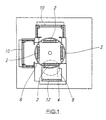
- FIG. 1 there is shown a representation of one type of chamber which is currently used for the application of coatings to optical lens. It should be appreciated that chambers having differing geometries are equally relevant to the invention disclosed herein and that reference to Figure 1 is for clarification purposes only.
- Figure 1 discloses apparatus for coating optical lens 2 held on a rotatable holder 4 within a chamber 6.
- the chamber is connected to a vacuum pump 8, the operation of which creates a vacuum in the chamber 6.
- apertures are provided to allow the inclusion of two magnetrons 10 and a plasma source 12.
- Each magnetron 10 contains a target of a metal and activation of the magnetrons causes sputtering of particles of metal into the chamber 6 and onto the optical lens 2 held on the rotating holder to coat the same.
- oxygen is supplied into the chamber and the plasma source, in this case an unbalanced magnetron, is operated to form a metal oxide coating on the optical lens.
- alternate operation of the magnetrons 10 provides a multilayered metal coating on the surfaces of the optical lens and this method and apparatus is currently used to provide lenses with multilayered coatings to provide the required optical effect.
- FIG 2 illustrates in schematic form the further apparatus and operations which are performed on the lenses in situ in the chamber and apparatus of Figure 1 according to the present invention.
- a plasma source 12 which is provided to operate in the vacuum chamber 6.
- these magnetrons are stopped and the plasma source 12 activated to create a plasma 18 in the chamber.
- gas supply means 19 are activated by the apparatus control system to supply a hydrocarbon gas/ air or inert gas mixture into the chamber 6.
- the gas supply means comprise a gas bottle 20 and a delivery control means 22 which may also comprise a gas monitor(not shown).
- the hydrocarbon groupings here represented by the numeral 24, split from the gas.
- the separated groupings then settle on the walls of the chamber and the optical lens 2 to provide the required coating on outer surface of the lens.
- the duration of the method described above is determined on the volume and speed of gas supply and the required thickness of coating.
- Figure 3 illustrates a cross section of an optical lens 2 which has been coated in the manner disclosed above and the cross section or "stack" of coatings consists of a conventional multi layer anti reflective coating 26 applied by conventional methods and an outer "hydrophobic" layer 28 having the required low surface energy characteristics applied by the methods and apparatus of this invention.
- the control system of the apparatus serves to stop the plasma source and oxygen supply and the operation of the magnetrons 10.
- the gas containing hydrocarbon groupings is then introduced into the chamber and the plasma source 12 activated to cause separation of at least some hydrocarbon groupings in the gas.
- the separated groupings are then free to land on available surfaces in the chamber including the surfaces of the optical lenses held therein.
- the outer surfaces of the optical lenses are coated with a relatively thin (typically 0.1-5 nanometres) coating of the hydrocarbon groupings.
- the coating applied provides lenses with outer surfaces which have sufficiently low surface energy characteristics to be significantly less susceptible to smearing and the attraction of foreign matter.
- the power of the plasma source is typically held between 15 and 25 Watts and the voltage at 600V.
- methane is introduced at a pressure of 5 10(-3) mBar and the lens is exposed for around 1 minute. This has been found to provide a coating on the lenses which, when tested with a drop of pure water thereon, provides a water drop contact angle of 89 degrees thus achieving the required low surface energy characteristics.
- the apparatus and method of the current invention provides a means whereby an outer coating can be applied to optical lenses to reduce the surface energy of the surface to within required parameters and said coating can be applied as an integral part of the conventional coating process and apparatus.
- an outer coating can be applied to optical lenses to reduce the surface energy of the surface to within required parameters and said coating can be applied as an integral part of the conventional coating process and apparatus.
Landscapes
- Chemical & Material Sciences (AREA)
- Metallurgy (AREA)
- Mechanical Engineering (AREA)
- Organic Chemistry (AREA)
- Chemical Kinetics & Catalysis (AREA)
- Engineering & Computer Science (AREA)
- Materials Engineering (AREA)
- General Chemical & Material Sciences (AREA)
- Physics & Mathematics (AREA)
- Inorganic Chemistry (AREA)
- Optics & Photonics (AREA)
- General Physics & Mathematics (AREA)
- Surface Treatment Of Optical Elements (AREA)
- Eyeglasses (AREA)
- Application Of Or Painting With Fluid Materials (AREA)
- Transition And Organic Metals Composition Catalysts For Addition Polymerization (AREA)
- Paints Or Removers (AREA)
- Materials For Medical Uses (AREA)
- Laminated Bodies (AREA)
Abstract
Description
Claims (18)
- A method for forming a low surface energy coating having a water contact angle of at least 68° on the surface of an optical lens, said method comprising placing the lens in a chamber, forming a vacuum in the chamber, providing a fluid to the chamber to be introduced into the chamber as a gas containing hydrocarbon groupings and characterised in that the chamber incorporates a magnetically enhanced plasma source which is activated when the gas containing the hydrocarbon groupings is introduced into the chamber to split at least some hydrocarbon groupings from the gas and at least some of said groupings applied to the surface of the optical lens to produce a low surface energy coating thereon.
- A method according to claim 1 characterised in that sufficient gas is supplied and hydrocarbon groupings split to provide a coating to a depth of 0.1 to 5 nanometers on said optical lens.
- A method according to claim 1 characterised in that the plasma source is any of an ion source, plasma source, unbalanced magnetron source or a low discharge means operable by any of d.c, a.c or r.f power means.
- A method according to claim 1 characterised in that the gas introduced into the chamber is hydrocarbon such as methane or propane.
- A method according to claim 4 characterised in that the gas is diluted in an inert gas or air.
- A method according to claim 5 characterised in that the gas is methane and the dilution range for methane in air is less than 5% by volume.
- A method according to claim 6 wherein the contact angle of a drop of pure water on the surface when methane is used is in the region of 76-90°.
- A method according to claim 5 characterised in that the contact angle of a drop of pure water on the surface when propane is used is 68-72°.
- A method of coating an optical lens comprising the steps of introducing at least one optical lens into a chamber, said chamber containing at least one magnetron with a target of metal therein, and a plasma source, pulling a vacuum in the chamber, activating the magnetron to sputter a metal onto the lens surface, introducing oxygen into the chamber and activating the plasma source to chemically react the material to provide the required optical coating on the lens, characterised in that the method includes a further step of switching off the at least one magnetron, plasma source and gas supply, introducing a gas containing hydrocarbon groupings into the chamber and activating the plasma source to split at least some hydrocarbon groupings from the gas and deposit the same onto the lens to form an outer coating thereon.
- A method according to claim 9 characterised in that two magnetrons are activated, each having a target of different metal to produce a multilayered optical coating on the lens prior to the introducing of the gas containing hydrocarbon groupings.
- A method according to any of the preceding claims characterised in that the method includes the further step of applying a gas containing groupings other than hydrocarbon groupings.
- A method according to claim 11 characterised in that a halogen containing gas such as CF4, C2F6, CCl4 is applied and creates a fluorinated or chlorinated surface.
- A method according to claim 11 characterised in that a silicon containing gas such as tetraethoxysilane, tetramethoxysilane, hexamethyldisiloxane is applied to create a silicon surface layer.
- Apparatus for the coating of optical lenses, said apparatus comprising a chamber, an optical lens holder within the chamber, a means for pulling a vacuum in the chamber, at least one magnetron with a metal target and a plasma source, drive means for moving optical lens on the holder past the magnetron and plasma source and control means for activating the magnetron and plasma source, and characterised in that the apparatus further comprises a source for gas containing hydrocarbon groupings and supply means for introducing the gas into the chamber and, when said plasma source is operated when the gas is introduced, to split at least some hydrocarbon groupings from said gas in the chamber.
- Apparatus according to claim 14, characterised in that the gas source is a conventional gas bottle and the supply means include a control device for controlling the supply of the gas from the bottle into the chamber.
- Apparatus according to claim 15 characterised in that the control device is in turn operated by the control means for the activation of the plasma source and magnetron.
- Apparatus according to any of claims 14 to 16 characterised in that the supply means allows the gas to be diluted in an inert gas, or in air, prior to final compression to atmospheric pressure by the vacuum pump.
- Apparatus according to any of claims 14 to 17 characterised in that the supply means includes a combustible gas sensor, flow meter or other means to monitor the level of dilution.
Applications Claiming Priority (3)
| Application Number | Priority Date | Filing Date | Title |
|---|---|---|---|
| GB9420089A GB9420089D0 (en) | 1994-10-05 | 1994-10-05 | Coatings for optical lens having low surface energy properties |
| GB9420089 | 1994-10-05 | ||
| PCT/GB1995/002339 WO1996011289A1 (en) | 1994-10-05 | 1995-10-03 | Low surface energy coatings |
Publications (2)
| Publication Number | Publication Date |
|---|---|
| EP0784714A1 EP0784714A1 (en) | 1997-07-23 |
| EP0784714B1 true EP0784714B1 (en) | 1998-11-04 |
Family
ID=10762387
Family Applications (1)
| Application Number | Title | Priority Date | Filing Date |
|---|---|---|---|
| EP95932855A Revoked EP0784714B1 (en) | 1994-10-05 | 1995-10-03 | Low surface energy coatings |
Country Status (6)
| Country | Link |
|---|---|
| EP (1) | EP0784714B1 (en) |
| AT (1) | ATE173033T1 (en) |
| AU (1) | AU3573995A (en) |
| DE (1) | DE69505837T2 (en) |
| GB (1) | GB9420089D0 (en) |
| WO (1) | WO1996011289A1 (en) |
Families Citing this family (5)
| Publication number | Priority date | Publication date | Assignee | Title |
|---|---|---|---|---|
| JP3760528B2 (en) * | 1996-11-07 | 2006-03-29 | ソニー株式会社 | Filter for display element |
| DE19704947A1 (en) * | 1997-02-10 | 1998-08-13 | Leybold Systems Gmbh | Method and device for the protective coating of reflective layers |
| US6266193B1 (en) | 1997-07-24 | 2001-07-24 | Cpfilms Inc. | Anti-reflective composite |
| US6583935B1 (en) | 1998-05-28 | 2003-06-24 | Cpfilms Inc. | Low reflection, high transmission, touch-panel membrane |
| US6918987B2 (en) * | 2003-02-07 | 2005-07-19 | Lord Corporation | Surface preparation of rubber for coatings or bonding |
Family Cites Families (7)
| Publication number | Priority date | Publication date | Assignee | Title |
|---|---|---|---|---|
| US4444805A (en) * | 1980-07-17 | 1984-04-24 | Barr & Stroud Limited | Optical coating |
| DE3316693A1 (en) * | 1983-05-06 | 1984-11-08 | Leybold-Heraeus GmbH, 5000 Köln | METHOD FOR PRODUCING AMORPHOUS CARBON LAYERS ON SUBSTRATES AND SUBSTRATES COATED BY THE METHOD |
| JPH07113682B2 (en) * | 1987-03-03 | 1995-12-06 | 株式会社ニコン | Lens that does not easily attach dirt |
| US5073785A (en) * | 1990-04-30 | 1991-12-17 | Xerox Corporation | Coating processes for an ink jet printhead |
| US5268217A (en) * | 1990-09-27 | 1993-12-07 | Diamonex, Incorporated | Abrasion wear resistant coated substrate product |
| GB9101106D0 (en) * | 1991-01-18 | 1991-02-27 | Cray Microcoat Ltd | Ion vapour deposition apparatus and method |
| DE4211962A1 (en) * | 1992-04-09 | 1993-10-14 | Leybold Ag | Plasma coating plastics article in vacuum - comprises using vacuum vessel contg. inlets and outlets for material flow control which forms process atmos., esp. from gaseous hydrocarbon |
-
1994
- 1994-10-05 GB GB9420089A patent/GB9420089D0/en active Pending
-
1995
- 1995-10-03 AU AU35739/95A patent/AU3573995A/en not_active Abandoned
- 1995-10-03 EP EP95932855A patent/EP0784714B1/en not_active Revoked
- 1995-10-03 WO PCT/GB1995/002339 patent/WO1996011289A1/en not_active Ceased
- 1995-10-03 AT AT95932855T patent/ATE173033T1/en not_active IP Right Cessation
- 1995-10-03 DE DE69505837T patent/DE69505837T2/en not_active Expired - Fee Related
Also Published As
| Publication number | Publication date |
|---|---|
| EP0784714A1 (en) | 1997-07-23 |
| DE69505837D1 (en) | 1998-12-10 |
| GB9420089D0 (en) | 1994-11-16 |
| ATE173033T1 (en) | 1998-11-15 |
| AU3573995A (en) | 1996-05-02 |
| DE69505837T2 (en) | 1999-06-10 |
| WO1996011289A1 (en) | 1996-04-18 |
Similar Documents
| Publication | Publication Date | Title |
|---|---|---|
| JP4144909B2 (en) | Method for producing graded layer | |
| US4400410A (en) | Coating insulating materials by glow discharge | |
| US5364666A (en) | Process for barrier coating of plastic objects | |
| US7880966B2 (en) | Optical article including a layer siox as main component and manufacturing method of the same | |
| US5192523A (en) | Method for forming diamondlike carbon coating | |
| BE1019991A3 (en) | METHOD FOR DEPOSITION OF LAYERS ON LOW PRESSURE PECVD GLASS SUBSTRATE. | |
| EP0743375B1 (en) | Method of producing diamond-like-carbon coatings | |
| WO2001040537A1 (en) | Method for producing fluorinated diamond-like carbon films | |
| JP2001514328A (en) | Jet plasma deposition method and apparatus for coating and coating thereof | |
| JP2001514328A5 (en) | ||
| EP0947601A1 (en) | Organic substrate having optical layers deposited by magnetron sputtering and method for preparing it | |
| JPH0247256A (en) | Formation of an oxide coating by reactive-sputtering | |
| Imai et al. | Hydrogen-free fluorinated DLC films with high hardness prepared by using T-shape filtered arc deposition system | |
| US4740442A (en) | Optical coating | |
| US4444805A (en) | Optical coating | |
| JPH0430561B2 (en) | ||
| Boeira et al. | Influence of base pressure prior to deposition on the adhesion behaviour of carbon thin films on steel | |
| JPH01201461A (en) | Method for coating synthetic resin plate | |
| US10011522B2 (en) | Method for treating antireflection coatings on an optical substrate, the thus obtained optical substrate and device for carrying gout said method | |
| WO2008007180A1 (en) | Glass with scratch-resistant coating | |
| WO1996011289A1 (en) | Low surface energy coatings | |
| EP0413617A1 (en) | Method for depositing thin layers | |
| Yoshinori Yamada et al. | X-ray photoelectron spectroscopy of fluorocarbon films deposited by RF sputtering | |
| López et al. | Substrate temperature effects on film chemistry in plasma depositions of organics. II. Polymerizable precursors | |
| EP0647727B1 (en) | Production of carriers for surface plasmon resonance |
Legal Events
| Date | Code | Title | Description |
|---|---|---|---|
| PUAI | Public reference made under article 153(3) epc to a published international application that has entered the european phase |
Free format text: ORIGINAL CODE: 0009012 |
|
| 17P | Request for examination filed |
Effective date: 19961213 |
|
| AK | Designated contracting states |
Kind code of ref document: A1 Designated state(s): AT BE CH DE DK ES FR GB GR IE IT LI LU MC NL PT SE |
|
| 17Q | First examination report despatched |
Effective date: 19970924 |
|
| GRAG | Despatch of communication of intention to grant |
Free format text: ORIGINAL CODE: EPIDOS AGRA |
|
| GRAG | Despatch of communication of intention to grant |
Free format text: ORIGINAL CODE: EPIDOS AGRA |
|
| GRAH | Despatch of communication of intention to grant a patent |
Free format text: ORIGINAL CODE: EPIDOS IGRA |
|
| GRAH | Despatch of communication of intention to grant a patent |
Free format text: ORIGINAL CODE: EPIDOS IGRA |
|
| GRAA | (expected) grant |
Free format text: ORIGINAL CODE: 0009210 |
|
| AK | Designated contracting states |
Kind code of ref document: B1 Designated state(s): AT BE CH DE DK ES FR GB GR IE IT LI LU MC NL PT SE |
|
| PG25 | Lapsed in a contracting state [announced via postgrant information from national office to epo] |
Ref country code: SE Free format text: LAPSE BECAUSE OF FAILURE TO SUBMIT A TRANSLATION OF THE DESCRIPTION OR TO PAY THE FEE WITHIN THE PRESCRIBED TIME-LIMIT Effective date: 19981104 Ref country code: NL Free format text: LAPSE BECAUSE OF FAILURE TO SUBMIT A TRANSLATION OF THE DESCRIPTION OR TO PAY THE FEE WITHIN THE PRESCRIBED TIME-LIMIT Effective date: 19981104 Ref country code: GR Free format text: LAPSE BECAUSE OF NON-PAYMENT OF DUE FEES Effective date: 19981104 Ref country code: BE Free format text: LAPSE BECAUSE OF FAILURE TO SUBMIT A TRANSLATION OF THE DESCRIPTION OR TO PAY THE FEE WITHIN THE PRESCRIBED TIME-LIMIT Effective date: 19981104 Ref country code: AT Free format text: LAPSE BECAUSE OF FAILURE TO SUBMIT A TRANSLATION OF THE DESCRIPTION OR TO PAY THE FEE WITHIN THE PRESCRIBED TIME-LIMIT Effective date: 19981104 |
|
| REF | Corresponds to: |
Ref document number: 173033 Country of ref document: AT Date of ref document: 19981115 Kind code of ref document: T |
|
| REG | Reference to a national code |
Ref country code: CH Ref legal event code: EP |
|
| REF | Corresponds to: |
Ref document number: 69505837 Country of ref document: DE Date of ref document: 19981210 |
|
| REG | Reference to a national code |
Ref country code: CH Ref legal event code: NV Representative=s name: ABREMA AGENCE BREVETS ET MARQUES GANGUILLET & HUMP |
|
| REG | Reference to a national code |
Ref country code: IE Ref legal event code: FG4D |
|
| PG25 | Lapsed in a contracting state [announced via postgrant information from national office to epo] |
Ref country code: PT Free format text: LAPSE BECAUSE OF FAILURE TO SUBMIT A TRANSLATION OF THE DESCRIPTION OR TO PAY THE FEE WITHIN THE PRESCRIBED TIME-LIMIT Effective date: 19990204 Ref country code: DK Free format text: LAPSE BECAUSE OF FAILURE TO SUBMIT A TRANSLATION OF THE DESCRIPTION OR TO PAY THE FEE WITHIN THE PRESCRIBED TIME-LIMIT Effective date: 19990204 |
|
| PG25 | Lapsed in a contracting state [announced via postgrant information from national office to epo] |
Ref country code: ES Free format text: LAPSE BECAUSE OF FAILURE TO SUBMIT A TRANSLATION OF THE DESCRIPTION OR TO PAY THE FEE WITHIN THE PRESCRIBED TIME-LIMIT Effective date: 19990205 |
|
| ET | Fr: translation filed | ||
| NLV1 | Nl: lapsed or annulled due to failure to fulfill the requirements of art. 29p and 29m of the patents act | ||
| PLBQ | Unpublished change to opponent data |
Free format text: ORIGINAL CODE: EPIDOS OPPO |
|
| PLBI | Opposition filed |
Free format text: ORIGINAL CODE: 0009260 |
|
| PLBF | Reply of patent proprietor to notice(s) of opposition |
Free format text: ORIGINAL CODE: EPIDOS OBSO |
|
| 26 | Opposition filed |
Opponent name: ROBERT BOSCH GMBH Effective date: 19990715 |
|
| PG25 | Lapsed in a contracting state [announced via postgrant information from national office to epo] |
Ref country code: LU Free format text: LAPSE BECAUSE OF NON-PAYMENT OF DUE FEES Effective date: 19991003 Ref country code: IE Free format text: LAPSE BECAUSE OF NON-PAYMENT OF DUE FEES Effective date: 19991003 |
|
| PLBF | Reply of patent proprietor to notice(s) of opposition |
Free format text: ORIGINAL CODE: EPIDOS OBSO |
|
| PLBF | Reply of patent proprietor to notice(s) of opposition |
Free format text: ORIGINAL CODE: EPIDOS OBSO |
|
| PLBF | Reply of patent proprietor to notice(s) of opposition |
Free format text: ORIGINAL CODE: EPIDOS OBSO |
|
| PG25 | Lapsed in a contracting state [announced via postgrant information from national office to epo] |
Ref country code: MC Free format text: LAPSE BECAUSE OF NON-PAYMENT OF DUE FEES Effective date: 20000430 |
|
| REG | Reference to a national code |
Ref country code: IE Ref legal event code: MM4A |
|
| PGFP | Annual fee paid to national office [announced via postgrant information from national office to epo] |
Ref country code: GB Payment date: 20010102 Year of fee payment: 6 Ref country code: DE Payment date: 20010102 Year of fee payment: 6 |
|
| PGFP | Annual fee paid to national office [announced via postgrant information from national office to epo] |
Ref country code: FR Payment date: 20010122 Year of fee payment: 6 |
|
| PGFP | Annual fee paid to national office [announced via postgrant information from national office to epo] |
Ref country code: CH Payment date: 20010131 Year of fee payment: 6 |
|
| RDAH | Patent revoked |
Free format text: ORIGINAL CODE: EPIDOS REVO |
|
| RDAG | Patent revoked |
Free format text: ORIGINAL CODE: 0009271 |
|
| STAA | Information on the status of an ep patent application or granted ep patent |
Free format text: STATUS: PATENT REVOKED |
|
| 27W | Patent revoked |
Effective date: 20010419 |
|
| GBPR | Gb: patent revoked under art. 102 of the ep convention designating the uk as contracting state |
Effective date: 20010419 |
|
| REG | Reference to a national code |
Ref country code: CH Ref legal event code: PL |