EP0784413B1 - Routeur N x N de longueur d'onde, procédé de routage optique et réseau de communication associé - Google Patents
Routeur N x N de longueur d'onde, procédé de routage optique et réseau de communication associé Download PDFInfo
- Publication number
- EP0784413B1 EP0784413B1 EP96402801A EP96402801A EP0784413B1 EP 0784413 B1 EP0784413 B1 EP 0784413B1 EP 96402801 A EP96402801 A EP 96402801A EP 96402801 A EP96402801 A EP 96402801A EP 0784413 B1 EP0784413 B1 EP 0784413B1
- Authority
- EP
- European Patent Office
- Prior art keywords
- router
- inputs
- outputs
- couplers
- routers
- Prior art date
- Legal status (The legal status is an assumption and is not a legal conclusion. Google has not performed a legal analysis and makes no representation as to the accuracy of the status listed.)
- Expired - Lifetime
Links
- 230000003287 optical effect Effects 0.000 title claims description 50
- 238000000034 method Methods 0.000 title claims description 21
- 238000004891 communication Methods 0.000 title claims description 9
- 230000005540 biological transmission Effects 0.000 claims description 57
- 238000000411 transmission spectrum Methods 0.000 claims description 19
- 238000009826 distribution Methods 0.000 claims description 4
- 238000009827 uniform distribution Methods 0.000 claims 1
- 239000000835 fiber Substances 0.000 description 42
- 238000001228 spectrum Methods 0.000 description 26
- 235000021183 entrée Nutrition 0.000 description 8
- VYPSYNLAJGMNEJ-UHFFFAOYSA-N Silicium dioxide Chemical compound O=[Si]=O VYPSYNLAJGMNEJ-UHFFFAOYSA-N 0.000 description 6
- 230000008569 process Effects 0.000 description 6
- 210000001520 comb Anatomy 0.000 description 5
- 239000011159 matrix material Substances 0.000 description 5
- 230000003595 spectral effect Effects 0.000 description 5
- 230000008054 signal transmission Effects 0.000 description 4
- 230000009467 reduction Effects 0.000 description 3
- 239000000377 silicon dioxide Substances 0.000 description 3
- 230000001174 ascending effect Effects 0.000 description 2
- 230000000295 complement effect Effects 0.000 description 2
- 230000008878 coupling Effects 0.000 description 2
- 238000010168 coupling process Methods 0.000 description 2
- 238000005859 coupling reaction Methods 0.000 description 2
- 238000001514 detection method Methods 0.000 description 2
- 238000010494 dissociation reaction Methods 0.000 description 2
- 230000005593 dissociations Effects 0.000 description 2
- 238000005516 engineering process Methods 0.000 description 2
- 230000004907 flux Effects 0.000 description 2
- 238000000926 separation method Methods 0.000 description 2
- 238000011144 upstream manufacturing Methods 0.000 description 2
- 230000004075 alteration Effects 0.000 description 1
- 230000003321 amplification Effects 0.000 description 1
- 238000003491 array Methods 0.000 description 1
- 230000005465 channeling Effects 0.000 description 1
- 230000001427 coherent effect Effects 0.000 description 1
- 238000011161 development Methods 0.000 description 1
- 230000018109 developmental process Effects 0.000 description 1
- 230000000694 effects Effects 0.000 description 1
- 230000001788 irregular Effects 0.000 description 1
- 238000002955 isolation Methods 0.000 description 1
- 238000003199 nucleic acid amplification method Methods 0.000 description 1
- 239000013307 optical fiber Substances 0.000 description 1
- 230000010287 polarization Effects 0.000 description 1
- 238000011084 recovery Methods 0.000 description 1
- 230000035945 sensitivity Effects 0.000 description 1
- 239000007787 solid Substances 0.000 description 1
- 230000009897 systematic effect Effects 0.000 description 1
- 230000002123 temporal effect Effects 0.000 description 1
Images

Classifications
-
- H—ELECTRICITY
- H04—ELECTRIC COMMUNICATION TECHNIQUE
- H04Q—SELECTING
- H04Q11/00—Selecting arrangements for multiplex systems
- H04Q11/0001—Selecting arrangements for multiplex systems using optical switching
Definitions
- the present invention relates to a router N x N of length wave, as well as an associated routing method, more particularly for a communications network.
- the telecommunications networks thus obtained make necessary the realization of commutations in great number by the through complex devices of the optical switch type.
- router N x N wavelength or WDM Widelength Division Multiplexer
- WDM Widelength Division Multiplexer
- N diffracting input elements respectively at the inputs
- N diffracting output elements arranged opposite the input diffracting elements and connected respectively at the outputs.
- Each of the diffracting elements input is able to produce for a given signal transmitted to a wavelength, an image arranged in a focal plane corresponding to any of the diffracting output elements.
- the selection of the output element is subject to the length signal wave.
- each input fiber-output fiber pair is therefore associated transmission wavelength.
- the global spectrum of transmission of the entire router N x N is thus presented under the shape of a comb with teeth located at these wavelengths.
- 2N-1 lengths separate waveforms are used in the transmission spectrum.
- the wavelength ranges between the teeth are lost areas. Since the tape spectral usability is limited, this results in a limitation of the number of transmission wavelengths. The possible number users is thus considerably restricted. For example, for a total spectral band limited to 30 nm, and the spacing between two transmission wavelengths being 1 nm, the number of transmission wavelengths cannot exceed 30, which restricts the number of users to fifteen.
- the teeth of the transmission spectrum have a width at half height or FWHM (Full Width Half-Maximum) usually small compared to length spacing transmission wave, which makes it difficult to select a emission wavelength, because positioning in a spectrum tooth requires high precision.
- FWHM Full Width Half-Maximum
- the ratio R of the width at half height of the teeth on their spacing indeed increases with the ratio of the diameter of the heart fibers over their distance.
- the ratio R reach a value of 0.4 when fibers with hearts of diameter 10 ⁇ m are spaced successively by 22 ⁇ m.
- the present invention relates to an N x N wavelength router valid for a large number of users, implying low losses and simple to carry out and to implement.
- the present invention is also directed towards a method of optical routing easy to implement and avoiding interference between signals.
- the invention also aims at a communications network based on optical means, valid for a large number user-friendly, reliable, involving low energy losses, and simple to make and use.
- the invention relates to a router N x N of length waveform with N inputs and N outputs, intended to transmit optical signals each having a wavelength, inputs to the exits.
- the N x N router also includes means switch capable of routing each of the optical signals of one any of the N inputs to any of the N outputs in function of the signal wavelength.
- the combs of the m routers n x n are different from each other, so as to make selection possible wavelength function for any of the N inputs of the router N x N, one of the m routers n x n and one of the n outputs of this router n x n.
- the transmission spectrum of an optical router is called the spectral distribution of the light flux at its outputs, produced by a luminous flux of spectrum extended over the entire band of operation of the router applied to all of its inputs.
- the router according to the invention implements different spectra according to the different routers n x n making it possible to select the wavelength, for a given input, of the router n x n concerned and within it, the intended exit route.
- This device therefore no time multiplexing required and allows upstream use n x n routers, a simple assembly of channel switches such as that claims.
- the router N X N can admit a spectrum of transmission in the form of a comb with very close teeth.
- the number N input and output can be significantly increased, without risk of crosstalk and without any particular technical problem.
- the ratio R for the overall transmission spectrum can be greatly increased.
- the relative widening of the width of teeth therefore allows a selection of emission wavelengths less strict than in existing devices.
- the transmission spectrum of each of the m routers n x n includes wavelength bands and each of these bands comprising teeth, the transmission spectra of m n x n routers have their bands interspersed.
- This configuration makes it possible to obtain a spectrum of transmission with complementary bands from different n x n routers. This can be particularly advantageous when transmission wavelengths are grouped by packets in each of the n x n routers.
- the teeth of the overall transmission spectrum alternatively come from a separate n x n router, which allows to obtain with respect to each of the routers n x n taken in isolation, a the closer the teeth, the greater the number of routers n x n is large.
- the ratio R can thus be multiplied by m.
- the comb of each of m routers n x n has teeth completely dissociated from the teeth other combs.
- the teeth of the global transmission spectrum can thus be clearly distinguished from each other, while being close. of the overlapping teeth from different spectra of routers n x n are however also possible.
- each couplers m x m is an achromatic coupler with distribution uniform energy between its outputs.
- each of the couplers m x m is a wavelength distribution coupler capable of transmitting energy of an optical signal having a wavelength, only by the output of the coupler m x m connected to the router n x n whose comb understands this wavelength.
- This second embodiment is advantageous in that it avoids any loss of energy due to the m x m couplers, by channeling the signals upstream from the routers n x n as a function of the length waveform of the optical signal.
- the m x m couplers are composed of 2 x 2 couplers each having two inputs and two outputs.
- the router N x N advantageously includes a first level of 2 x 2 couplers whose inputs are the inputs of the router N x N, and a last level of 2 x 2 couplers whose outputs are connected to the inputs n x n routers.
- the inputs of the 2 x 2 couplers which do not belong to the first level, are connected to outputs of 2 x 2 couplers, and the outputs of the 2 x 2 couplers which do not belong not at the last level, are connected to 2 x 2 coupler inputs.
- the N x N router has couplers with Y each having a main arm and two secondary arms, the inputs and outputs of the router N x N being connected to the arms main couplers in Y.
- the router N x N allows to send optical signals simultaneously from its inputs to its outputs and from its outputs to its inputs, the optical signals flowing in opposite directions in the two secondary arms of each of Y couplers.
- the invention also relates to an optical routing method implemented by means of an N ⁇ N router according to the invention.
- this process we send optical signals each having a wavelength, from the inputs of the N x N router to its outputs.
- the method according to the invention is characterized in that for ability to simultaneously send optical signals of at least two of the m inputs of at least one of the n couplers m x m, in direction of the same one of the N outputs of the router N x N without risk of interference, optical signals have different wavelengths each other.
- the output of the router N x N being one of the n outputs of one of the m routers n x n and the comb of the router n x n having teeth, the wavelengths of the optical signals are distributed in one of the teeth.
- the invention also relates to a communications network.
- a communications network comprising at least one N x N router having any one of the preceding characteristics, or more of them in association, or implementing any of previous features of the routing process.
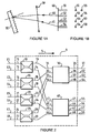
- a basic 4 x 4 router used in an N x N router according to the invention, comprises a diffraction grating 50 disposed opposite of a plan 62 of fibers, as can be seen in FIG. 1A.
- the 4 x 4 router also includes focusing optics such as than a lens 59.
- Input fibers 51, 52, 53, 54 lead to the plan 62 of fibers being arranged in line, as well as output fibers 55, 56, 57, 58, the plane 62 of fibers being shown from the front in Figure 1B.
- Input fibers 51-54 are arranged parallel to the output fibers 55-58 and facing each other in the plan 62.
- the network 50 is capable of producing any input fibers 51-54 an image arranged in a focal plane which matches any of the output fibers 55-58 function of The wavelength.
- An incident ray 60 containing information transmitted by one of the input fibers from a user transmitter is thus transformed into a returned ray 61 by means of the lens 59 and the network 50 which is directed towards a receiving user through one of the output fibers.
- any of the four sending users can communicate with any of the four receiving users.
- the relationships giving the wavelengths which make it possible to pass from any of the input fibers to any of the output fibers can be shown diagrammatically in a 4 ⁇ 4 matrix of the type shown below.
- the rows correspond to the input fibers 51-54 and the columns to the output fibers 55-58.
- All communications through the 4 x 4 router require 7 wavelengths ⁇ i , i varying from 1 to 7, classified in ascending order.
- nxn router similar to that described, with any n, can be carried out as for the 4 x 4 router.
- the fibers are identical and periodically spaced, 2n-1 transmission wavelengths are required.
- the diffraction grating 50 can be replaced or supplemented by a set of multi-dielectric filters, or by a set of phased array grating.
- a rung of Michelson, very effective for wavelengths of orders can also be used.
- one or more strips of lasers can be used as a means of referral input, and one or more photodetector arrays like output reception means.
- a single strip of input and output fibers can also be employed.
- this includes a mirror and a diffraction grating, the mirror, the network and the fibers being fixed in a block of solid silica.
- a input fiber strip and output fiber strip parallels are placed in front of a photoetched slot on a plane reflection grating, perpendicular to grooves.
- a mirror concave is able to transform a divergent beam coming from any of the input fibers in a parallel bundle.
- the network is able to transform this beam by dispersing it angularly towards the concave mirror.
- This beam then has an image formed at one end of one of the output fibers in a position which depends on the wavelength.
- This configuration is aplanatic, afocal and has an amplification of 1.
- the network is advantageously in a Littrow configuration.
- the component uses a strip of fibers entering the home of the dispersive network device, so that no light can be coupled directly to the output fibers at a wavelength corresponding to a Littrow condition.
- the output fiber strip is arranged for this above that of the input fibers.
- An 8 x 8 router referenced 1 according to the invention, shown in Figure 2, has eight inputs E1-E8 and eight outputs S1-S8.
- This 8 x 8 router is intended to transmit optical signals from any input E i to any output S i , in direction 5, the path of the optical signal being determined by its wavelength.
- Router 1 has two 4 x 4 routers referenced 30 and 40 respectively, which are 4 x 4 routers such as the one previously described ( Figures 1A and 1B). Optionally, it can also be traditional 4 x 4 routers.
- the routers 30 and 40 each include four inputs 31-34 and 41-44 respectively, and four outputs 35-38 and 45-48. The outputs 35-38, 45-48 of routers 30 and 40 lead directly to outputs S1-S8 of router 1.
- Router 1 also has four couplers achromatic in X referenced 10, 15, 20, 25 each having respectively two inputs 11, 12; 16, 17; 21, 22 and 26, 27, and two outputs 13, 14; 18, 19; 23, 24 and 28, 29.
- Entries 11, 12; 16, 17; 21, 22; 26, 27 of couplers 10, 15, 20, 25 in X correspond respectively to the inputs E1-E8 of router 1.
- Each of the couplers 10, 15, 20, 25 also has one of its outputs, respectively 13, 18, 23, 28, connected to one of the inputs, respectively 31, 32, 33, 34, of a first router 30, and its other output, respectively 14, 19, 24, 29, connected to one of the inputs, 41, 42, 43, 44, respectively, of the second router 40.
- the respective transmission spectra 67 and 68 of the routers 30 and 40 are in the form of combs with teeth, respectively 71-73 and 74-76.
- the spectra 67 and 68 being plotted along axes 65 and 66, respectively of wavelengths ⁇ and of transmission T, have their teeth 71-76 centered on the transmission wavelengths of routers 30 and 40.
- the teeth 71, 72 and 73 of the spectrum 67 are, for example, respectively centered on the wavelengths ⁇ 1 , ⁇ 2 , ⁇ 3 , the wavelengths ⁇ i being classified in ascending order .
- the teeth 74, 75 and 76 of the spectrum 68 are centered on the wavelengths ⁇ ' 1 , ⁇ ' 2 , ⁇ ' 3 .
- the teeth 71-76 have heights approximately identical and equal to H.
- Special features of the spectra 67 and 68 are constituted by the widths L of the teeth 71-76 at mid-height H / 2 and by the spacings D between the successive transmission wavelengths ⁇ i .
- the widths L at mid-height are similar for all the teeth, as well as the spacings D.
- the routers 30 and 40 are chosen so that their transmission wavelengths ⁇ i and ⁇ ' i are interposed. So we have: ⁇ ' 1 ⁇ 1 ⁇ ' 2 ⁇ 2 ⁇ ' 3 ⁇ 3
- a signal at a given wavelength arrives at any one of the inputs E i of the router 1, then at one of the couplers 10, 15, 20, 25.
- the signal is then transmitted to the two outputs of this coupler with in each an energy divided by two, the couplers being achromatic.
- the optical signal thus reaches an input from each of the routers 30, 40. Since the signal wavelength corresponds to a transmission wavelength of only one of the spectra 67, 68 of the routers 30, 40 , the signal is only transmitted in this router, to the appropriate output selected according to the wavelength.
- the targeted output S j is thus reached by the signal.
- Router 1 therefore has a global transmission spectrum which jointly admits teeth 71-76 of the two spectra 67 and 68 routers 30 and 40.
- the spacing D between transmission wavelengths is thus significantly reduced, this reduction being able to go up to a factor 2.
- the number of transmission wavelengths can therefore be multiplied by 2, and therefore also the number of users.
- the R report can itself be multiplied by 2, making selection easier of a transmission wavelength.
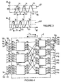
- a second example of embodiment of an N x N router according to the invention is provided by a 12 x 12 wavelength router referenced 2, shown in Figure 4.
- This router has twelve inputs P1-P12 and twelve outputs P13-P24. It also includes four 3 x 3 wavelength routers referenced 130, 140, 150, 160, each having three entries 131-133, 141-143 respectively, 151-153, 161-163 and three outputs 134-136, 144-146, 154-156 and 164-166.
- the outputs of routers 130, 140, 150, 160 correspond respectively at outputs P13-P24 of router 2.
- Router 2 also has three couplers 4 x 4 achromatic, referenced 80, 90 and 100. These couplers each have four entries, respectively 81-84, 91-94 and 101-104 and four outputs, respectively 85-88, 95-98 and 105-108.
- the inputs of couplers 80, 95, 100 correspond respectively to the inputs P1-P12 of router 2, and the four outputs of each of the couplers 80, 90, 100 are each connected to an input from one of the routers 130, 140, 150, 160.
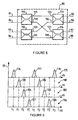
- Each of the couplers 80, 90, 100 is actually made up of from four couplers in X. So, as we can see on the Figure 5, the coupler 80 has four 2 x 2 couplers referenced 111-114 each comprising two inputs, respectively 81, 82; 83, 84; 125, 126; 127, 128 and two outputs, respectively 121, 122; 123, 124; 85, 86; 87, 88.
- Two of the X couplers, 111, 112 are arranged on a first level, their entries 81-84 being those of coupler 80.
- the other two couplers in X, 113 and 114 are arranged on a second level, their outputs 85-88 being those of the coupler 80.
- each of the two couplers 111, 112 of the first level are each connected to a input 125-128 of one of the couplers 113, 114 of the second level.
- the two other 4 x 4 couplers, 90 and 100, are made so similar.
- Router 2 also includes 24 achromatic couplers in Referenced 120 there, each of them comprising a main arm 115 and two secondary arms 116 and 117. Each of the inputs P1-P12 and of outputs P13-P24 of router 2 is connected to the main arm 115 of one of the Y couplers 120.
- the 120 couplers are intended for serve as means of transmission, with two-way propagation, two branches 116, 117 of each of the couplers 120 being provided for opposite directions 118, 119 of signal propagation.
- the router 2 is thus intended for signal transmissions, both in one direction 3 from inputs P1-P12 to outputs P13-P24, and in an opposite direction 4.
- the routers 130, 140, 150, 160 have transmission spectra 175, 180, 183, 186 having comb shapes comprising teeth, respectively 176-178; 181, 182; 184, 185; 187, 188, centered on wavelengths ⁇ 1 , ⁇ 2 , ⁇ 3 ; ⁇ ' 1 , ⁇ ' 2 ; ⁇ '' 1 , ⁇ '' 2 ; ⁇ ''' 1 , ⁇ '' 2 .
- a signal at a given wavelength reaches one of the inputs of one of the couplers 80, 90 or 100 and is transmitted to the four outputs of this 4 x 4 coupler with a reduction energy by a factor of 4.
- the optical signal is thus transmitted to a input of each of the four routers 130, 140, 150, 160.
- the signal wavelength is only a wavelength transmission of only one of the spectra 175, 180, 183, 186 of 3 x 3 routers, signal transmission only takes place in this router, to the selected output according to the wavelength of the signal.
- Router 2 therefore has a general transmission spectrum having the set of teeth 176-178, 181, 182, 184, 185, 187, 188 spectra 175, 180, 183, 186 of the four routers 130, 140, 150, 160.
- the width at mid-height of the teeth is thus preserved, and the inter-wavelength spacing of transmission substantially reduced, this reduction being able to reach a factor of 4.
- signals can come simultaneously from outputs P13-P24 to inputs P1-P12, according to the same principle.
- the same wavelength can thus be used in both directions of communication between two users, which doubles the router capabilities 2.
- routers 1 and 2 are low, corresponding to factors of the order of 2 and 4 respectively.
- the presence of optical amplifiers in the switching compensates for the effects of these losses. It is however possible to make losses due to couplers negligible, in combination with couplers and selection means wavelengths.
- couplers negligible, in combination with couplers and selection means wavelengths.
- These means can be obtained, for example, by a two-wave interferometer, such as a Michelson which can be placed in an integrated optical plate. In this case, the optical signal leaving one of the couplers is not transmitted selectively only to the router having a wavelength of transmission corresponding to the wavelength of the signal.
- the teeth of the combs of separate n x n routers have been shown dissociated, they can also overlap, the important thing being the centering of each of the teeth over a length given transmission wave.
- the alternation of spectral components from one router to another can relate to bands and no longer teeth, each band comprising several teeth. This configuration is advantageous in particular if the spacing Inter-wavelength transmission is irregular, the teeth being grouped by packages.
- the invention can be applied in cascade on two or more levels.
- router 1 previously described ( Figure 2), it is desirable that several any of the inputs E1-E8 can communicate simultaneously with the same outputs S1-S8.
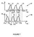
- a first embodiment consists in sending, respectively at E1 and E2, signals having distinct wavelengths, but arranged on the same tooth of the transmission spectrum 67 of the router 30, as shown in the Figure 7.
- tooth 71 of spectrum 67 corresponds to an optical path from input 31 of router 30 to output S1
- the wavelength for E1 is equal to ⁇ 1a and that for E2, ⁇ 1b .
- the wavelengths ⁇ 1a , ⁇ 1b are arranged so as to produce on the tooth 71 preferably high amplitudes of transmission, that is to say close to the maximum value 70 reached approximately for the wavelength ⁇ 1 average, on which the tooth 71 is centered.
- the lengths ⁇ 1a and ⁇ 1b are therefore preferably close to ⁇ 1 . What is more, they are advantageously symmetrical with respect to ⁇ 1 , so that the corresponding transmission amplitudes are equal or close.
- the signals received simultaneously in S1 from E1 and E2 can be reconstructed by separation of the wavelengths ⁇ 1a and ⁇ 1b .
- This separation can, for example, be carried out by means of a coherent detection filter.
- routing method for simultaneously send signals from E1 and E2 to S1, we choose respectively two wavelengths of distinct orders, allowing both signals to be routed from input 31 of router 30 to its exit 35.
- This method of implementation is, like the first, applicable to all of the inputs E1-E8, the two modes can be possibly combined.
- one or the other can be used according to the spectrum teeth.
- the routing method described consisting of sending to the inputs of the same signal coupler with wavelengths separate, to transmit them simultaneously to the same output of the router N X N, is also valid for m greater than 2.
- signals from the four inputs P1-P4 can be sent simultaneously associated with coupler 80 to the same output P13 of router 2.
- the four signals corresponding respectively to the four P1-P4 inputs have separate wavelengths.
- the four wavelengths are distributed in the tooth of the spectrum 175 associated with the transmission of a signal from the input 131 of the router 130 to its output 134, this tooth being, for example , that referenced 176.
- the four wavelengths are advantageously arranged close to ⁇ 1 , and symmetrically with respect to it.
- the light sources connected to the P1-P12 inputs of router 2 and the detection means connected to the outputs P13-P24 are however preferably provided for respectively transmitting and detecting automatically signals at defined distinct wavelengths in the routing process chosen, which allows recognition signals in all cases.
- the router of the invention can be implemented in a technology based on optical fibers or in integrated optics.
- the router N x N of the invention can be the subject of an implementation partial work, only part of its N entries being used to receive optical signals.
- the number of N entries actually in service being equal to M, with M ⁇ N, the router N x N then behaves like an M x N router.
- the router according to the invention is a 40 x 40 router comprising two 20 x 20 routers and 20 achromatic couplers in X.
- Each of the 20 x 20 routers corresponds to a silica component, with a focal length of 119.512 mm, a network of 600 lines / mm, with a fiber holder with double strip of fibers spaced 42.54 ⁇ m apart.
- the first router is in collimation in the center of the field for 1548.5145 nm, and the second router has a spectrum shifted by half a period thanks to a stickers at 1548.5145 ⁇ 0.4 nm.
- a double bar of 20 equally spaced fibers is disposed at the hearth.
- the transmission wavelengths of the first router 20 x 20 range from 1533.2 nm to 1563.9 nm with inter-length spacing 0.8 nm transmission wave.
- the spacing between transmission wavelengths (equal 0.8 nm) is chosen constant, which avoids additional losses up to 3 dB.
- 20 x 20 routers are compatible with data rates of 10 Gbit / second on each channel.
- the 20 x 20 wavelength matrix of the first 20 X router 20 was calculated taking into account the exact silica index of each wavelength, by iterative adjustment to values of reference.
- the matrix obtained is shown in Figure 8; the 20 columns corresponding to the inputs, and the 20 rows to the outputs.
- the indicated values are expressed in nm.
- the default of adjustment remains less than 0.008 nm, which is negligible.
- An 80 x 80 router includes two 40 x 40 and 40 routers achromatic couplers in X.
- These 40 x 40 routers are compatible with data rates of Gbit / second on each channel.
- a 6 x 6 router has two 3 x 3 routers made using 6 multiplexers each made in technology with shared optical function with focal length 119.512 mm, space between fibers 32 ⁇ m and network of 300 lines / mm.
- the multiplexers of the first 3 x 3 router are associated with wavelengths 1552.517 nm, 1550.916 nm and 1549.315 nm. Those the second 3 x 3 router, at the same wavelengths offset by ⁇ 0.8 nm.
- the 6 x 6 router also has 3 X couplers made in fused fibers technique with close hearts (fused coupler).
Landscapes
- Engineering & Computer Science (AREA)
- Computer Networks & Wireless Communication (AREA)
- Optical Communication System (AREA)
Description
- n coupleurs m x m ayant chacun m entrées et m sorties, N étant égal à n X m et les N entrées des n coupleurs m x m étant les entrées du routeur N x N,
- m routeurs n x n ayant chacun n entrées et n sorties, chacune des n entrées étant reliée à une des sorties de, respectivement les n coupleurs m x m et les N sorties des m routeurs n x n étant les sorties du routeur N x N. Chacun des routeurs n x n est apte à aiguiller un signal optique ayant une longueur d'onde, de l'une quelconque de ses n entrées vers l'une quelconque de ses n sorties, en fonction de la longueur d'onde du signal, le routeur n x n ayant un spectre de transmission en fonction de la longueur d'onde sous forme d'un peigne.
- un support de transmission comprenant une première rangée des n entrées et une seconde rangée des n sorties, les première et seconde rangées étant disposées parallèlement et le support de transmission ayant une surface de transmission plane,
- un élément diffractant disposé en regard de la surface de transmission,
- une optique de focalisation placée entre le support de transmission et l'élément diffractant,
- les Figures 1A et 1B sont des représentations schématiques d'un routeur 4 x 4 de longueur d'onde utilisé dans un routeur N x N selon l'invention, la Figure 1A montrant une vue d'ensemble du routeur 4 x 4 et la Figure 1B, une vue de face de son plan de fibres ;
- la Figure 2 représente un routeur 8 x 8 de longueur d'onde selon l'invention, comportant quatre coupleurs 2 x 2 et deux routeurs 4 x 4 tels que celui schématisés sur les Figures 1A et 1B ;
- la Figure 3 montre les spectres de transmission respectifs des deux routeurs 4 x 4 du routeur 8 x 8 de la Figure 2 ;
- la Figure 4 est une représentation schématique d'un routeur 12 x 12 de longueur d'onde selon l'invention, comportant trois coupleurs 4 x 4 et quatre routeurs 3 x 3, et à double sens de transmission ;
- la Figure 5 est une vue détaillée d'un des coupleurs 4 x 4 du routeur 12 x 12 de la Figure 4 ;
- la Figure 6 montre les spectres de transmission respectifs des quatre routeurs 3 x 3 du routeur 12 x 12 de la Figure 4 ;
- la Figure 7 montre les spectres de transmission respectifs des deux routeurs 4 x 4 du routeur 8 x 8 de la Figure 2, et représente les longueurs d'onde des signaux transmis dans un mode préféré de mise en oeuvre du procédé de routage ;
- la Figure 8 montre dans un mode de mise en oeuvre la matrice de longueur d'onde 20 X 20 d'un routeur 20 x 20.

2n-1 longueurs d'onde de transmission sont nécessaires.
- pertes de 4 dB ± 1 dB;
- diaphotie intrinsèque < - 55 dB d'une voie à une autre ;
- perte retour < - 25 dB ;
- sensibilité de polarisation < 1 dB ;
- élargissement d'impulsion dû au réseau égal à 38,6 ps ;
- précision de voie de longueur d'onde : ± 0,05 nm.
- espacement inter-longueurs d'onde de transmission : 0,4 nm
- largeur à mi-hauteur des dents : 0,25 nm ± 0,03 nm
- pertes < 7 dB ± 2 dB ;
- diaphotie d'une voie à une autre < - 60 dB.
Claims (15)
- Routeur (1,1) N x N de longueur d'onde comportant N entrées (E1-E8, P1-P12) et N sorties (S1-S8, P13-P24), destiné à transmettre des signaux optiques ayant chacun une longueur d'onde, des entrées vers les sorties, le routeur N x N (1,2) comportant également des moyens d'aiguillage aptes à aiguiller chacun des signaux optiques de l'une quelconque des N entrées vers l'une quelconque des N sorties en fonction de la longueur d'onde dudit signal,
les moyens d'aiguillage comportant:caractérisé en ce que les peignes des m routeurs n x n sont différents les uns des autres, de manière à rendre possible une sélection en fonction de la longueur d'onde pour une quelconque desdites N entrées (E1-E8, P1-P12) du routeur (1, 2) N x N, à la fois d'un des m routeurs n x n et d'une des n sorties dudit routeur n x n.n coupleurs m x m (10, 15, 20, 25, 80, 90, 100) ayant chacun m entrées (11, 12, 16, 17, 21, 22, 26, 27, 81-84,91-94, 101-104) et m sorties (13, 14, 18, 19, 23, 24, 28, 29, 85-88, 95-98, 105-108), N étant égal à n x m et les N entrées des n coupleurs m x m (10, 15, 20, 25, 80, 90, 100) étant les entrées (E1-E8, P1-P12) du routeur N x N (1,2).m routeurs n x n (30, 40, 130, 140, 150, 160) ayant chacun n entrées(31-34, 41-44, 131-133, 141-143, 151-153, 161-163) et n sorties (35-38, 45-48, 134-136, 144-146, 154-156, 164-166), chacune desdites n entrées étant reliée à une des sorties de, respectivement, les n coupleurs m x m (10, 15, 20, 25, 80, 90, 100) et les N sorties des m routeurs n x n (30, 40, 130, 140, 150, 160) étant les sorties (S1-S8, P13-P24) du routeur N x N, chacun des routeurs n x n étant apte à aiguiller un signal optique ayant une longueur d'onde, de l'une quelconque de ses n entrées vers l'une quelconque de ses n sorties, en fonction de sa longueur d'onde dudit signal, ledit routeur n x n (30, 40, 130, 140, 150, 160) ayant un spectre de transmission (67, 68, 175, 180, 183, 186) en fonction de la longueur d'onde sous forme d'un peigne, - Routeur N x N selon la revendication 1, caractérisé en ce que le spectre de transmission (67, 68, 175, 180, 183, 186) de chacun des m routeurs n x n (30, 40, 130, 140, 150, 160) comprenant des bandes de longueurs d'onde et chacune desdites bandes comprenant des dents (71-76, 176-178, 181, 182, 184, 185, 187, 188), les spectres de transmission des m routeurs n x n ont leurs bandes intercalées.
- Routeur N x N selon la revendication 2, caractérisé en ce que les peignes (67, 68, 175, 180, 183, 186) des m routeurs n x n (30, 40, 130, 140, 150, 160) ont leurs dents (71-76, 176-178, 181, 182, 184, 185, 187, 188) intercalées.
- Routeur N x N selon l'une quelconque des revendications précédentes, caractérisé en ce que le peigne (67, 68, 175, 180, 183, 186) de chacun des m routeurs n x n (30, 40, 130, 140, 150, 160) a des dents(71-76, 176-178, 181, 182, 184, 185, 187, 188) complètement dissociées des dents des autres peignes.
- Routeur N x N selon l'une quelconque des revendications précédentes, caractérisé en ce que chacun des coupleurs m x m (10, 15, 20, 25, 80, 90, 100) est un coupleur achromatique à répartition uniforme d'énergie entre ses sorties (13, 14, 18, 19, 23, 24, 28, 29, 85-88, 95-98, 105-108).
- Routeur N x N selon l'une quelconque des revendications 1 à 4, caractérisé en ce que chacun des coupleurs m x m (10, 15, 20, 25, 80, 90, 100) est un coupleur à répartition de longueur d'onde apte à transmettre de l'énergie d'un signal optique ayant une longueur d'onde, uniquement par la sortie dudit coupleur m x m reliée au routeur n x n (30, 40, 130, 140, 150, 160) dont le peigne (67, 68, 175, 180, 183, 186) comprend ladite longueur d'onde.
- Routeur N x N selon l'une quelconque des revendications précédentes, caractérisé en ce que les coupleurs m x m (10, 15, 20, 80, 90, 100) sont composés de coupleurs 2 x 2 (10, 15, 20, 111-114) ayant chacun deux entrées (11, 12, 16, 17, 21, 22, 26, 27, 81-84, 125-128) et deux sorties (13, 14, 18, 19, 23, 24, 28, 29, 85-88, 121-124).
- Routeur N x N selon la revendication 7, caractérisé en ce qu'il comprend un premier niveau de coupleurs 2 x 2 (111, 112) dont les entrées (81-84) sont les entrées (P1-P4) du routeur N x N (2), et un dernier niveau de coupleurs 2 x 2 (113, 114) dont les sorties (85-88) sont reliées aux entrées (131, 141, 151, 161) des routeurs n x n (130, 140, 150, 160), les entrées (125-128) des coupleurs 2 x 2 (113, 114) qui n'appartiennent pas audit premier niveau étant reliées à des sorties (121-124) de coupleurs 2 x 2 (111, 112), et les sorties (121-124) des coupleurs 2 x 2 (111, 112) qui n'appartiennent pas audit dernier niveau étant reliées à des entrées (125-128) de coupleurs 2 x 2 (113, 114).
- Routeur N x N selon l'une quelconque des revendications précédentes, caractérisé en ce qu'il comporte des coupleurs en Y (120) ayant chacun un bras principal (115) et deux bras secondaires (116, 117), les entrées (P1-P12) et les sorties (P13-P24) du routeur N x N (2) étant reliées aux bras principaux (115) desdits coupleurs en Y (120), ledit routeur N x N (2) permettant d'envoyer des signaux optiques simultanément de ses entrées vers ses sortis et de ses sorties vers ses entrées, lesdits signaux optiques circulant en sens opposées (3, 4) dans les d'eux bras secondaires (116, 117) de chacun des coupleurs en Y.
- Routeur N x N selon l'une quelconque des revendications précédentes, caractérisé en ce que chacun des routeurs n x n comprend:l'élément diffractant et l'optique de focalisation étant aptes à produire de l'une quelconque des entrées, une image correspondant à l'une quelconque des sorties en fonction de la longueur d'onde desdits signaux optiques.un support de transmission comprenant une première rangée des n entrées et une seconde rangée des n sorties, les première et seconde rangées étant disposées parallèlement et le support de transmission ayant une surface de transmission plane,un élément diffractant en regard de ladite surface de transmission,une optique de focalisation placée entre le support de transmission et l'élément diffractant,
- Procédé de routage optique mis en oeuvre au moyen d'un routeur N x N (1, 2) conforme à l'une quelconque des revendications précédentes, dans lequel on envoie des signaux optiques ayant chacun une longueur d'onde, des entrées (E1-E8, P1-P12) du routeur N x N vers ses sorties (S1-S8, P13-P24), caractérisé en ce que pour pouvoir envoyer simultanément des signaux optiques d'au moins deux des m entrées (11, 12, 16, 17, 21, 22, 26, 27, 81-84, 91-94, 101-104) d'au moins un des n coupleurs m x m (10, 15, 20, 25, 80, 90, 100) en direction d'une même des N sorties (S1-S8, P13-P24) du routeur N x N (1, 2) sans risque de brouillage, lesdits signaux optiques ont des longueurs d'onde distinctes les unes des autres.
- Procédé de routage optique selon la revendication 11, caractérisé en ce que ladite sortie (S1-S8) du routeur N x N (1) étant une des n sorties (35-38, 45-48) d'un des m routeurs n x n (30, 40) et le peigne (67, 68) dudit routeur n x n (30, 40) ayant des dents (71-76), les longueurs d'onde desdits signaux optiques sont réparties dans une desdites dents (71-76).
- Procédé de routage optique selon la revendication 11, caractérisé en ce que les longueurs d'onde desdits signaux optiques ont des ordres distincts.
- Réseau de communications comprenant au moins un routeur N x N (1, 2) selon l'une quelconque des revendications 1 à 10.
- Réseau de communications comprenant au moins un routeur N x N (1,2) mettant en oeuvre un procédé de routage selon l'une quelconque des revendications 11 à 13.
Applications Claiming Priority (4)
| Application Number | Priority Date | Filing Date | Title |
|---|---|---|---|
| FR9600170A FR2743430A1 (fr) | 1996-01-09 | 1996-01-09 | Routeur n x n de longueur d'onde et reseau de communications associe |
| FR9600170 | 1996-01-09 | ||
| FR9602496A FR2743424B1 (fr) | 1996-01-09 | 1996-02-28 | Routeur n x n de longueur d'onde, procede de routage optique et reseau de communications associes |
| FR9602496 | 1996-02-28 |
Publications (2)
| Publication Number | Publication Date |
|---|---|
| EP0784413A1 EP0784413A1 (fr) | 1997-07-16 |
| EP0784413B1 true EP0784413B1 (fr) | 2002-10-30 |
Family
ID=26232426
Family Applications (1)
| Application Number | Title | Priority Date | Filing Date |
|---|---|---|---|
| EP96402801A Expired - Lifetime EP0784413B1 (fr) | 1996-01-09 | 1996-12-18 | Routeur N x N de longueur d'onde, procédé de routage optique et réseau de communication associé |
Country Status (4)
| Country | Link |
|---|---|
| US (1) | US5838848A (fr) |
| EP (1) | EP0784413B1 (fr) |
| DE (1) | DE69624551T2 (fr) |
| FR (1) | FR2743424B1 (fr) |
Families Citing this family (36)
| Publication number | Priority date | Publication date | Assignee | Title |
|---|---|---|---|---|
| US6631018B1 (en) * | 1997-08-27 | 2003-10-07 | Nortel Networks Limited | WDM optical network with passive pass-through at each node |
| US6580537B1 (en) | 1998-07-17 | 2003-06-17 | Regents Of The University Of California, The | High-throughput, low-latency next generation internet networks using optical label switching and high-speed optical header generation, detection and reinsertion |
| US6111673A (en) | 1998-07-17 | 2000-08-29 | Telcordia Technologies, Inc. | High-throughput, low-latency next generation internet networks using optical tag switching |
| US6525850B1 (en) | 1998-07-17 | 2003-02-25 | The Regents Of The University Of California | High-throughput, low-latency next generation internet networks using optical label switching and high-speed optical header generation, detection and reinsertion |
| US6307653B1 (en) * | 1999-03-24 | 2001-10-23 | Tellium, Inc | Optical matrix protection system |
| AU779320B2 (en) * | 1999-04-30 | 2005-01-13 | Spi Lasers Uk Limited | An optical fibre arrangement |
| US6415080B1 (en) | 1999-09-03 | 2002-07-02 | Zolo Technologies, Inc. | Echelle grating dense wavelength division multiplexer/demultiplexer |
| US6519062B1 (en) * | 2000-02-29 | 2003-02-11 | The Regents Of The University Of California | Ultra-low latency multi-protocol optical routers for the next generation internet |
| US6426831B1 (en) | 2000-02-29 | 2002-07-30 | Massachusetts Institute Of Technology | EIT based optical switch/wavelength converter |
| US6366717B1 (en) * | 2000-03-22 | 2002-04-02 | Marconi Communications, Inc. | Apparatus for distributing optical fiber transmission paths |
| US6594437B1 (en) | 2000-08-15 | 2003-07-15 | Fci Americas Technology, Inc. | Optical fiber separation and regrouping device |
| US6597452B1 (en) | 2000-11-17 | 2003-07-22 | Jobin Yvon, Inc. | Compact littrow-type scanning spectrometer |
| US6754450B2 (en) | 2001-01-30 | 2004-06-22 | The Regents Of The University Of California | Optical layer multicasting using a single sub-carrier header with active header detection, deletion, and new header insertion via opto-electrical processing |
| US6757497B2 (en) | 2001-01-30 | 2004-06-29 | The Regents Of The University Of California | Optical layer multicasting using a single sub-carrier header and a multicast switch with active header insertion via reflective single sideband optical processing |
| US6934472B2 (en) * | 2001-01-30 | 2005-08-23 | The Regents Of The University Of California | Optical layer multicasting using a single sub-carrier header and a multicast switch with active header insertion |
| US6873797B2 (en) | 2001-01-30 | 2005-03-29 | The Regents Of The University Of California | Optical layer multicasting |
| US6850515B2 (en) | 2001-01-30 | 2005-02-01 | The Regents Of The University Of California | Optical layer multicasting using a single sub-carrier header and a multicast switch with active header insertion via light circulation |
| US6813276B2 (en) | 2001-01-30 | 2004-11-02 | The Regents Of The University Of California | Optical layer multicasting using a single sub-carrier header with active header detection, deletion, and re-insertion via a circulating optical path |
| US6850707B1 (en) | 2001-01-30 | 2005-02-01 | The Regents Of The University Of California | Secure optical layer multicasting to effect survivability |
| US6757496B2 (en) | 2001-01-30 | 2004-06-29 | The Regents Of The University Of California | Optical layer multicasting using a single sub-carrier header and an optical multicasting switch |
| US6768871B2 (en) | 2001-01-30 | 2004-07-27 | The Regents Of The University Of California | Optical layer multicasting using a multicast switch to effect survivability and security |
| US6819666B2 (en) | 2001-01-30 | 2004-11-16 | The Regents Of The University Of California | Optical layer multicasting using multiple sub-carrier headers with header detection, deletion, and insertion via reflective single sideband optical processing |
| KR100399049B1 (ko) * | 2001-04-16 | 2003-09-26 | 한국전자통신연구원 | 고속 파장 선택기와 그를 이용한 고속 광자 집적 회로형공간 및 파장 다중 채널 선택 장치 |
| US6990268B2 (en) * | 2002-03-08 | 2006-01-24 | Pts Corporation | Optical wavelength cross connect architectures using wavelength routing elements |
| WO2003076981A2 (fr) * | 2002-03-08 | 2003-09-18 | Pts Corporation | Architectures d'un raccord croise de longueurs d'onde optiques utilisant des elements d'acheminement de longueurs d'onde, et procede de realisation d'ameliorations en service |
| US7079723B2 (en) * | 2002-03-08 | 2006-07-18 | Pts Corporation | Optical wavelength cross connect architectures using wavelength routing elements |
| US6813408B2 (en) * | 2002-03-08 | 2004-11-02 | Pts Corporation | Methods for performing in-service upgrades of optical wavelength cross connects |
| US8086101B2 (en) * | 2002-03-08 | 2011-12-27 | Altera Corporation | Multi-city DWDM wavelength link architectures and methods for upgrading |
| US7149425B2 (en) * | 2002-04-30 | 2006-12-12 | Lucent Technologies Inc. | Monitoring system for an optical transmitter |
| JP4291281B2 (ja) * | 2005-02-03 | 2009-07-08 | 富士通株式会社 | 情報処理システム、計算ノード、情報処理システムの制御方法 |
| EP2083298B1 (fr) | 2008-01-23 | 2017-05-10 | Yenista Optics | Dispositif optique comportant un système de dispersion compact |
| US8849115B2 (en) * | 2008-03-11 | 2014-09-30 | Ciena Corporation | Directionless optical architecture and highly available network and photonic resilience methods |
| US8625994B2 (en) * | 2008-03-11 | 2014-01-07 | Ciena Corporation | Directionless reconfigurable optical add-drop multiplexer systems and methods |
| US9331807B2 (en) * | 2012-10-15 | 2016-05-03 | Telefonaktiebolaget L M Ericsson (Publ) | Service edge hub device and methods in an optical network node |
| WO2020086744A1 (fr) * | 2018-10-23 | 2020-04-30 | The Regents Of The University Of California | Multiplexeur en longueur d'onde comprenant des coupleurs optiques en cascade |
| US12111210B2 (en) * | 2021-07-08 | 2024-10-08 | Apple Inc. | Light source modules for noise mitigation |
Family Cites Families (3)
| Publication number | Priority date | Publication date | Assignee | Title |
|---|---|---|---|---|
| FR2696891B1 (fr) * | 1992-10-09 | 1994-11-04 | Alcatel Nv | Matrice de commutation optique. |
| US5657406A (en) * | 1994-09-23 | 1997-08-12 | United Technologies Corporation | Efficient optical wavelength multiplexer/de-multiplexer |
| US5668652A (en) * | 1995-02-24 | 1997-09-16 | Nippon Telegraph & Telephone Corporation | Optical WDM (wavelength division multiplexing) transmission system and method for configuring the same |
-
1996
- 1996-02-28 FR FR9602496A patent/FR2743424B1/fr not_active Expired - Fee Related
- 1996-12-18 DE DE69624551T patent/DE69624551T2/de not_active Expired - Fee Related
- 1996-12-18 EP EP96402801A patent/EP0784413B1/fr not_active Expired - Lifetime
-
1997
- 1997-01-08 US US08/780,357 patent/US5838848A/en not_active Expired - Fee Related
Also Published As
| Publication number | Publication date |
|---|---|
| FR2743424B1 (fr) | 1998-03-27 |
| FR2743424A1 (fr) | 1997-07-11 |
| US5838848A (en) | 1998-11-17 |
| EP0784413A1 (fr) | 1997-07-16 |
| DE69624551T2 (de) | 2003-09-04 |
| DE69624551D1 (de) | 2002-12-05 |
Similar Documents
| Publication | Publication Date | Title |
|---|---|---|
| EP0784413A1 (fr) | Routeur N x N de longueur d'onde, procédé de routage optique et réseau de communication associé | |
| US8320769B2 (en) | Transverse-mode multiplexing for optical communication systems | |
| US6269203B1 (en) | Holographic optical devices for transmission of optical signals | |
| FR2741494A1 (fr) | Procede et appareil pour brouiller la polarisation de lumieres de signal formant une lumiere de signal multiplexee par repartition en longueurs d'onde | |
| EP0005093B1 (fr) | Circuit optique intégré de démultiplexage et procédé de fabrication de ce circuit | |
| FR2609180A1 (fr) | Multiplexeur-demultiplexeur utilisant un reseau concave elliptique et realise en optique integree | |
| US20030128917A1 (en) | Method and apparatus for optical signal processing using an optical tapped delay line | |
| CN1290433A (zh) | 监测多波长信号用的光学装置 | |
| CA2292276A1 (fr) | Procede de reduction des distortions d'intensite induites par la modulation de phase croisee dans un systeme de transmission a fibre optique a multiplexage de longueur d'onde et unite pour la mise en oeuvre du procede | |
| EP0887672A1 (fr) | Multiplexeur-démultiplexeur en longueur d'onde à fibres optiques | |
| EP1312181A2 (fr) | Dispositif et procede de surveillance de la qualite optique dans un reseau de communication optique | |
| Churin et al. | Design of free space WDM router based on holographic concave grating | |
| FR2731573A1 (fr) | Multiplexeur-demultiplexeur de longueurs d'onde optique | |
| FR2743430A1 (fr) | Routeur n x n de longueur d'onde et reseau de communications associe | |
| EP1433006B1 (fr) | Composant optique a fonction de separation spectrale | |
| EP0487391A1 (fr) | Module émetteur-récepteur optique bi-directionnel à plusieurs voies et répéteur optique utilisant ce module | |
| US20030091276A1 (en) | Grating-based MUX/DMUX with expanded waveguides | |
| FR3139396A1 (fr) | Routeur optique pour la distribution de signaux optiques | |
| Dianov et al. | Wavelength-division multiplexing of channels in fiber-optic communication lines | |
| CN119254332A (zh) | 一种密集波分复用水下无线光通信系统 | |
| FR2832882A1 (fr) | Routeur de longueur d'onde cyclique | |
| EP2282430B1 (fr) | Dispositif d'extraction multivoies de canaux WDM | |
| US20020033976A1 (en) | Method and device for switching wavelength division multiplexed optical signals using gratings | |
| WO2001078281A2 (fr) | Appareil de compression d'informations pour lignes a fibres optiques | |
| FR2884086A1 (fr) | Transmission optique entre une premiere unite et une pluralite de secondes unites connectees entre elles au moyen d'un reseau d'acces optique passif |
Legal Events
| Date | Code | Title | Description |
|---|---|---|---|
| PUAI | Public reference made under article 153(3) epc to a published international application that has entered the european phase |
Free format text: ORIGINAL CODE: 0009012 |
|
| AK | Designated contracting states |
Kind code of ref document: A1 Designated state(s): DE FR GB |
|
| 17P | Request for examination filed |
Effective date: 19980116 |
|
| 17Q | First examination report despatched |
Effective date: 19990305 |
|
| RAP1 | Party data changed (applicant data changed or rights of an application transferred) |
Owner name: HIGHWAVE OPTICAL TECHNOLOGIES |
|
| GRAG | Despatch of communication of intention to grant |
Free format text: ORIGINAL CODE: EPIDOS AGRA |
|
| GRAG | Despatch of communication of intention to grant |
Free format text: ORIGINAL CODE: EPIDOS AGRA |
|
| GRAH | Despatch of communication of intention to grant a patent |
Free format text: ORIGINAL CODE: EPIDOS IGRA |
|
| GRAH | Despatch of communication of intention to grant a patent |
Free format text: ORIGINAL CODE: EPIDOS IGRA |
|
| GRAA | (expected) grant |
Free format text: ORIGINAL CODE: 0009210 |
|
| AK | Designated contracting states |
Kind code of ref document: B1 Designated state(s): DE FR GB |
|
| REG | Reference to a national code |
Ref country code: GB Ref legal event code: FG4D Free format text: NOT ENGLISH |
|
| PGFP | Annual fee paid to national office [announced via postgrant information from national office to epo] |
Ref country code: FR Payment date: 20021129 Year of fee payment: 7 |
|
| REF | Corresponds to: |
Ref document number: 69624551 Country of ref document: DE Date of ref document: 20021205 |
|
| PGFP | Annual fee paid to national office [announced via postgrant information from national office to epo] |
Ref country code: GB Payment date: 20021218 Year of fee payment: 7 |
|
| GBT | Gb: translation of ep patent filed (gb section 77(6)(a)/1977) |
Effective date: 20021220 |
|
| PGFP | Annual fee paid to national office [announced via postgrant information from national office to epo] |
Ref country code: DE Payment date: 20030130 Year of fee payment: 7 |
|
| PLBE | No opposition filed within time limit |
Free format text: ORIGINAL CODE: 0009261 |
|
| STAA | Information on the status of an ep patent application or granted ep patent |
Free format text: STATUS: NO OPPOSITION FILED WITHIN TIME LIMIT |
|
| 26N | No opposition filed |
Effective date: 20030731 |
|
| PG25 | Lapsed in a contracting state [announced via postgrant information from national office to epo] |
Ref country code: GB Free format text: LAPSE BECAUSE OF NON-PAYMENT OF DUE FEES Effective date: 20031218 |
|
| PG25 | Lapsed in a contracting state [announced via postgrant information from national office to epo] |
Ref country code: DE Free format text: LAPSE BECAUSE OF NON-PAYMENT OF DUE FEES Effective date: 20040701 |
|
| GBPC | Gb: european patent ceased through non-payment of renewal fee |
Effective date: 20031218 |
|
| PG25 | Lapsed in a contracting state [announced via postgrant information from national office to epo] |
Ref country code: FR Free format text: LAPSE BECAUSE OF NON-PAYMENT OF DUE FEES Effective date: 20040831 |
|
| REG | Reference to a national code |
Ref country code: FR Ref legal event code: ST |