EP0784252B1 - Soft landing method for probe assembly - Google Patents
Soft landing method for probe assembly Download PDFInfo
- Publication number
- EP0784252B1 EP0784252B1 EP96307633A EP96307633A EP0784252B1 EP 0784252 B1 EP0784252 B1 EP 0784252B1 EP 96307633 A EP96307633 A EP 96307633A EP 96307633 A EP96307633 A EP 96307633A EP 0784252 B1 EP0784252 B1 EP 0784252B1
- Authority
- EP
- European Patent Office
- Prior art keywords
- probe assembly
- work surface
- machine part
- force
- soft contact
- Prior art date
- Legal status (The legal status is an assumption and is not a legal conclusion. Google has not performed a legal analysis and makes no representation as to the accuracy of the status listed.)
- Expired - Lifetime
Links
Images
Classifications
-
- G—PHYSICS
- G01—MEASURING; TESTING
- G01B—MEASURING LENGTH, THICKNESS OR SIMILAR LINEAR DIMENSIONS; MEASURING ANGLES; MEASURING AREAS; MEASURING IRREGULARITIES OF SURFACES OR CONTOURS
- G01B7/00—Measuring arrangements characterised by the use of electric or magnetic techniques
- G01B7/002—Constructional details of contacts for gauges actuating one or more contacts
-
- G—PHYSICS
- G05—CONTROLLING; REGULATING
- G05B—CONTROL OR REGULATING SYSTEMS IN GENERAL; FUNCTIONAL ELEMENTS OF SUCH SYSTEMS; MONITORING OR TESTING ARRANGEMENTS FOR SUCH SYSTEMS OR ELEMENTS
- G05B19/00—Program-control systems
- G05B19/02—Program-control systems electric
- G05B19/18—Numerical control [NC], i.e. automatically operating machines, in particular machine tools, e.g. in a manufacturing environment, so as to execute positioning, movement or co-ordinated operations by means of program data in numerical form
- G05B19/401—Numerical control [NC], i.e. automatically operating machines, in particular machine tools, e.g. in a manufacturing environment, so as to execute positioning, movement or co-ordinated operations by means of program data in numerical form characterised by control arrangements for measuring, e.g. calibration and initialisation, measuring workpiece for machining purposes
-
- H—ELECTRICITY
- H01—ELECTRIC ELEMENTS
- H01F—MAGNETS; INDUCTANCES; TRANSFORMERS; SELECTION OF MATERIALS FOR THEIR MAGNETIC PROPERTIES
- H01F3/00—Cores, Yokes, or armatures
- H01F3/08—Cores, Yokes, or armatures made from powder
-
- H—ELECTRICITY
- H01—ELECTRIC ELEMENTS
- H01F—MAGNETS; INDUCTANCES; TRANSFORMERS; SELECTION OF MATERIALS FOR THEIR MAGNETIC PROPERTIES
- H01F7/00—Magnets
- H01F7/06—Electromagnets; Actuators including electromagnets
- H01F7/066—Electromagnets with movable winding
-
- G—PHYSICS
- G05—CONTROLLING; REGULATING
- G05B—CONTROL OR REGULATING SYSTEMS IN GENERAL; FUNCTIONAL ELEMENTS OF SUCH SYSTEMS; MONITORING OR TESTING ARRANGEMENTS FOR SUCH SYSTEMS OR ELEMENTS
- G05B2219/00—Program-control systems
- G05B2219/30—Nc systems
- G05B2219/37—Measurements
- G05B2219/37411—Measure contact from force and velocity detection
-
- G—PHYSICS
- G05—CONTROLLING; REGULATING
- G05B—CONTROL OR REGULATING SYSTEMS IN GENERAL; FUNCTIONAL ELEMENTS OF SUCH SYSTEMS; MONITORING OR TESTING ARRANGEMENTS FOR SUCH SYSTEMS OR ELEMENTS
- G05B2219/00—Program-control systems
- G05B2219/30—Nc systems
- G05B2219/37—Measurements
- G05B2219/37622—Detect collision, blocking, stall by change, lag in position
-
- G—PHYSICS
- G05—CONTROLLING; REGULATING
- G05B—CONTROL OR REGULATING SYSTEMS IN GENERAL; FUNCTIONAL ELEMENTS OF SUCH SYSTEMS; MONITORING OR TESTING ARRANGEMENTS FOR SUCH SYSTEMS OR ELEMENTS
- G05B2219/00—Program-control systems
- G05B2219/30—Nc systems
- G05B2219/37—Measurements
- G05B2219/37624—Detect collision, blocking by measuring change of velocity or torque
-
- G—PHYSICS
- G05—CONTROLLING; REGULATING
- G05B—CONTROL OR REGULATING SYSTEMS IN GENERAL; FUNCTIONAL ELEMENTS OF SUCH SYSTEMS; MONITORING OR TESTING ARRANGEMENTS FOR SUCH SYSTEMS OR ELEMENTS
- G05B2219/00—Program-control systems
- G05B2219/30—Nc systems
- G05B2219/37—Measurements
- G05B2219/37625—By measuring changing forces in a time window
-
- G—PHYSICS
- G05—CONTROLLING; REGULATING
- G05B—CONTROL OR REGULATING SYSTEMS IN GENERAL; FUNCTIONAL ELEMENTS OF SUCH SYSTEMS; MONITORING OR TESTING ARRANGEMENTS FOR SUCH SYSTEMS OR ELEMENTS
- G05B2219/00—Program-control systems
- G05B2219/30—Nc systems
- G05B2219/50—Machine tool, machine tool null till machine tool work handling
- G05B2219/50109—Soft approach, engage, retract, escape, withdraw path for tool to workpiece
Definitions
- the present invention pertains generally to machines which are useful for assembling or manufacturing an end product. More particularly, the present invention pertains to methods for controlling the forces that move assembly machine parts during assembly or manufacture of the end product. The present invention is particularly, but not exclusively, useful for the manufacture of end products which incorporate very delicate or fragile components that require soft contact forces during assembly of the end product.
- the present invention relies on notions inherent in the mechanical concepts set forth above for the control of moving parts in an assembly and manufacturing machine.
- a machine used for the manufacture of an end product which incorporates a probe assembly that is to be moved, for whatever purpose, into contact with a work surface on the end product. Since the machine will necessarily operate to move one body (the probe assembly) into contact with another body (the work surface of the end product), forces will be generated against both bodies by this action.
- US Patent No. 5,446,323 in the name of Systems, Machines, Automation Components Corporation relates to a device and a method for moving and positioning an assembly component in an automated assembly operation.
- US Patent No. 4,547,847 relates to an adaptive control system for a turning machine which includes a soft engagement function by monitoring the machining power dissipated at a cutter tip.
- the present invention recognizes that by monitoring certain measurable values of the movement parameters of a particular machine part, the contact forces between the machine part and components of the end product being manufactured can be accurately controlled and thereby minimized. Stated differently, based on the basic mechanical concepts set forth above, the present invention recognizes that the measurable values of the movement parameters of the machine part which can be monitored to control the machine part are all force related.
- the present invention provides a method for moving a probe assembly into soft contact with a work surface comprises the steps of: a method for moving a machine part into soft contact with a work surface which comprises the steps of:
- the probe assembly may include a component part that is being held by the probe assembly.
- the approach position can be arbitrarily established in accordance with the desires of the operator, but preferably, the approach position places the probe assembly much closer than about one millimeter away from the work surface. In any event, the probe assembly is placed at the approach position for subsequent movement along a path from the approach position into soft contact with a predetermined point on the work surface.
- the probe assembly is held stationary at the approach position. Then, the forces which are acting to hold the probe assembly stationary are changed in magnitude until the inherent static friction forces that have been acting on the stationary probe assembly are overcome. When the static friction forces have been overcome, the system becomes dynamic and the probe assembly advances toward the work surface under the influence of the resultant force.
- the probe assembly As the probe assembly is advanced toward the work surface, it is monitored to determine when soft contact is made with the work surface.
- control modes of operation for determining soft contact are possible for the present invention.
- each of these control modes depends on a measurable parameter that is characteristic of the movement of the probe assembly.
- These measurable parameters include i) the probe's travel position on the path toward the work surface (position control mode), ii) its velocity (velocity control mode), and iii) the acceleration/ deceleration of the probe assembly (torque control mode).
- a load sensor can be mounted on the probe assembly and monitored for activation to indicate soft contact.
- none of the above mentioned measurable parameters are monitored and, instead, the probe assembly is allowed to merely advance into soft contact with the work surface under the influence of the resultant force (basic mode).
- an optical encoder or any type feedback device that is well known in the pertinent art, can be used to monitor the position of the probe assembly relative to the approach position.
- this position control mode an estimate is first made of the actual distance between the approach position and the work surface.
- the probe assembly is then allowed to advance toward the work surface under the influence of the resultant force. This advancement, however, is allowed only through a travel distance that is slightly greater than the estimated distance. Soft contact is determined to have occurred after the probe assembly has traversed the travel distance.
- the output from the encoder, or other feedback device is coupled with the output from a timer or clock to obtain the velocity of the probe assembly as it advances toward the work surface. Again, as in the position control mode, the probe assembly is advanced toward the work surface under the influence of the resultant force. In this mode, however, soft contact is determined to have occurred when the velocity of the probe assembly is equal to zero.
- An acceleration or torque control mode of operation is also provided as a modification of the velocity control mode.
- the time rate of change of velocity i.e. acceleration
- the encoder and the timer are monitored using the encoder and the timer. Because soft contact will result in an acceleration of the probe assembly (actually a deceleration), a determination that soft contact has occurred can be made when this acceleration exceeds a predetermined threshold value.
- the actual soft contact force between the probe assembly and the work surface can be monitored. This is done with a load sensor which can be mounted directly onto the probe assembly. In this mode of operation, activation of the load sensor determines when soft contact has been accomplished.
- the probe assembly is not monitored after it departs from the approach position. With no monitoring of the probe assembly, the operator accepts the contact between the probe assembly and the work surface as being a soft contact. As with all of the above mentioned modes of operation, the probe assembly is advanced toward the work surface under the influence of the resultant force. Importantly, for all modes of operation in the methods of the present invention, the resultant force is that force which is just necessary to overcome the static friction forces.
- the present invention provides a device for moving a probe assembly into soft contact with a work surface which comprises:
- a device for performing the methods of the present invention is shown and generally designated 10.
- the device 10 includes a linear motor of a type similar to the one disclosed and claimed in U.S. Patent No. 5,446,323 which issued to Neff et al. for an invention entitled “Actuator with Translational and Rotational Control", and which is assigned to the same assignee as the present invention.
- the actuator 12 is more clearly shown to include a reciprocating coil 14 which surrounds a magnet 16.
- a reciprocating coil 14 which surrounds a magnet 16.
- a flux field is established which interacts with the magnetic flux field of the magnet 16.
- this interaction creates forces on the coil 14.
- the magnitude and direction of the forces that are created on the coil 14 can be controlled to move the coil.
- the coil 14 can be made to reciprocate. If, as intended for the present invention, a probe assembly 18 is connected directly to the coil, the probe assembly 18 will move and reciprocate with the coil 14.
- the probe assembly 18 can be operated to place a component 20 into proper position on a work surface 22. As can be easily appreciated, such action could be used to create an end product 24.
- the present invention is not an assembly process per se. Instead, it is the control of contact forces between probe assembly 18 and component 20, and the subsequent contact force between probe assembly 18 and/or component 20 and work surface 22 that is of concern.
- a brief review of frictional forces will be helpful. To this end, consider Figure 3A wherein the body 26 is shown to have a weight W and to be resting on a surface 28.
- Figure 4A shows the free body diagram of probe assembly 18 as it is shown in Figure 4A.
- Figure 4A shows probe assembly 18 while it is held vertically above the work surface 22 in an approach position preparatory to contact with work surface 22.
- the forces acting on probe assembly 18 in this condition are i) its weight W, ii) all friction forces which are represented by F, and iii) the activating push/pull force P.
- the push/pull force P essentially represents the torque which is exerted on probe assembly 18 by the interaction between coil 14 and magnet 16.
- the friction forces F is the sum of all other mechanical forces which combine to resist any reciprocal movement of the probe assembly 18 in actuator 12.
- probe assembly 18 need not always be vertically oriented as shown in Figure 4A, consider also the more generalized free body diagram of probe assembly 18 that is shown in Figure 4B.
- Figure 4A By comparing Figure 4A with Figure 4B it will be seen that a change in the orientation of probe assembly from a vertical orientation ( Figure 4A) to an angled ( Figure 4B) causes a change in the direction that weight W acts on probe assembly 18. This will also affect the magnitude of force P that is necessary to maintain static equilibrium. The point to be made is, that regardless of the orientation of probe assembly 18, several forces will continue to act in some way against the probe assembly 18.
- the method of the present invention is shown as a logic flow chart and is generally designated 30.
- the probe assembly 18 is placed at an approach position. More specifically, to accomplish this step of method 30 the probe assembly 18 is moved into the approach position by the action of actuator 12. It may then, but not necessarily, be held stationary while in the approach position.
- the approach position can be arbitrarily selected by the operator. For purposes of discussion here, however, an approach position is selected such that the probe assembly 18 is located at a distance 34 from work surface 22. Further, the distance 34 is preferably much less than one millimeter. This distance 34 is shown in both Figures 4A and 4B.
- Box 36 indicates that a push/pull force (P) is to be applied to the probe assembly 18 while it is in the approach position. Further, the purpose of this push/pull force P is to advance the probe assembly 18 toward the work surface 22.
- the application of push/pull force (P) requires an appreciation of all of the other forces which are acting on probe assembly 18. Recall, that for a static equilibrium condition, the push/pull force P (i.e. torque from actuator 12) could be varied through a range. This could be done so long as the friction force F did not exceed the maximum static friction force F m .
- box 36 contemplates that the push/pull force P will be appropriately changed through the operation of actuator 12 to transition the probe assembly 18 from a static to a dynamic condition, i.e. P will be adjusted until P is equal to P t .
- this transition involves a change from the static stationary condition of probe assembly 18 at the approach position, into a dynamic condition wherein the probe assembly 18 advances toward work surface 22 along a path 38.
- Weight W will, of course, remain constant.
- the imbalance of forces on probe assembly 18 will disrupt its static equilibrium condition and cause the probe assembly 18 to accelerate toward work surface 22.
- the only force in this example which is controllable by the operator of method 30 is the push/pull force P.
- the step in method 30 that is contemplated by box 36 is the establishment of a threshold force P t that is of sufficient magnitude, and in the proper direction, to transition probe assembly 18 from its static condition at the approach position into a dynamic condition. With this transition, the probe assembly 18 will advance toward the work surface 22.
- probe assembly 18 need not be actually stopped at the approach position during each cycle in the execution of method 30. Indeed, as contemplated by the present invention, if a value for P t has been previously established, probe assembly 18 can be in continuous motion as it passes through the approach position. To initially establish the value for a push/pull force P t , the probe assembly 18 first needs to be stopped (i.e. placed in a static condition). The torque from actuator 12 is then varied to empirically determine a value for P t .
- the actuator 12 of the present invention includes an encoder 40.
- the encoder 40 can be of any type of position feedback sensor that is well known in the pertinent art.
- an optical encoder is considered,
- the encoder 40 includes an optical scanner 42 which is operationally associated with a scale 44 that is mounted on the probe assembly 18 for movement therewith.
- a timer 46 is included in the optical encoder 40.
- the position of probe assembly 18 relative to actuator 12 can be determined. Consequently, the position (S) of probe assembly 18 along path 38 can also be determined. Albeit, approximately. Further, by comparing changes in the position S of probe assembly 18 with predetermined intervals of time that are established by the timer 46 (i.e. dS/dt), the velocity (V) of probe assembly 18 along path 38 can also be determined. Still further, by monitoring the time rate of change in its velocity V (i.e. dV/dt),the accelerations (a) of probe assembly 18 along path 38 can be determined.
- box 48 of method 30 shows that an inquiry is made as to whether the velocity V of probe assembly 18 is monitored. If the answer to this inquiry is yes, box 50 then indicates that the next question concerns whether this velocity is equal to zero. If so, box 52 shows that a soft contact has been made. For purposes of identification and differentiation, this mode of operation in method 30 is sometimes referred to herein as the velocity mode.
- a refinement of the velocity mode of operation for the present invention can be made by maintaining the velocity at a constant magnitude.
- One advantage of this refinement is that it allows for compensation of small changes in the friction forces F which oppose advancement of the probe assembly 18.
- box 54 shows that an acceleration on probe assembly 18 which is above a predetermined absolute value will indicate a soft contact of the probe assembly 18 with work surface 22.
- This mode of operation in method 30 is sometimes referred to as the acceleration control mode.
- the inquiry is made at box 55 as to whether the position S of probe assembly 18 is monitored. If so, box 56 inquires as to whether the probe assembly 18 has moved along the path 38 through a distance D. To determine distance D, it is first necessary to make an estimate of the distance 34 between the work surface 22 and the probe assembly 18. This estimate is made with the probe assembly 18 in the approach position and can be incorporated into the set up of device 10. Regardless what the estimate for distance 34 may be, an incremental overshoot distance 58 (see Figures 4A and 4B) is added to the distance 34 to establish distance D.
- the overshoot distance 58 can be on the order of about one ten thousandth of an inch (0.0001 in.), and preferably even less. Soft contact of the probe assembly 18 with work surface 22 will then be determined as having occurred when the probe assembly 18 has traveled along path 38 through the distance D.
- An important consideration in this mode of operation for method 30 is that the encoder 40 can accurately measure the distances that have been traveled by probe assembly 18 along path 38. The encoder 40, however, does not measure the distance 34 that is characteristic of the approach position. This mode of operation is sometimes referred to as the position control mode.
- the position control mode can also be used, in conjunction with a clock (not shown) which will measure the time which has transpired after the probe assembly 18 has been monitored as being in a particular position.
- a clock not shown
- the passage of time after probe assembly 18 leaves the approach position can be used to determine whether soft contact has occurred.
- the probe assembly 18 is established in the approach position, it is then released under the influence of push/pull force P t , and after the passage of a predetermined time interval soft contact is accepted as having occurred.
- Figure 5 also indicates at box 60 that the landing force L (i.e. the actual force at contact between probe assembly 18 and work surface 22) can be monitored to determine whether the probe assembly 18 has made soft contact with the work surface 22.
- This mode of operation requires the use of a load sensor 62 which can be mounted on probe assembly 18, such as is shown in Figure 2.
- load sensor 62 can be of any type well known in the pertinent art, such as a type manufactured by Futek.
- box 64 of method 30 when a load sensor 62 is incorporated into probe assembly 18, a soft contact between the probe assembly 18 and the work surface 22 will be determined upon the activation of load sensor 62. Stated differently, the presence of a landing force L will activate the load sensor 62 to determine soft contact.
- Method 30 also indicates that soft landing can be determined when no measurable parameters of the movement of probe assembly 18 are specifically monitored.
- the inquiries at boxes 48, 54 and 60 all receive negative responses.
- neither velocity V, nor position S, nor landing force L are monitored.
- This is a so-called basic case wherein soft contact is to be accepted as having occurred after the proper push/pull force P has been established to advance probe assembly 18 toward work surface 22.
- the push/pull force P is applied to the probe assembly 18 while the probe assembly 18 is in the approach position. Further, the push/pull force P is established as being the force P, with appropriate magnitude and direction, which is just necessary to transition the probe assembly 18 from a static condition to a dynamic condition.
- the method 30 of the present invention contemplates an ability to selectively use a particular mode of operation. This selection will, of course, depend upon the needs and desires of the operator. Further, regardless which mode of operation is to be used, the methods of the present invention contemplate that soft contact can be made with landing forces of below fifty grams (50 gm), and conceivable as low as approximately one hundredth of a gram (0.01 gm). Further, after soft contact has been determined, it is also within the contemplation of the present invention that the push/pull force P can be appropriately altered to maintain the static contact force between the probe assembly 18 and the work surface 22 at a value equal to, or nearly equal to, the soft contact landing force L. On the other hand, push/pull force P can be altered after soft contact to create whatever force is desired between probe assembly 18 and work surface 22.
Landscapes
- Physics & Mathematics (AREA)
- Engineering & Computer Science (AREA)
- Electromagnetism (AREA)
- General Physics & Mathematics (AREA)
- Power Engineering (AREA)
- Human Computer Interaction (AREA)
- Manufacturing & Machinery (AREA)
- Automation & Control Theory (AREA)
- Length Measuring Devices With Unspecified Measuring Means (AREA)
- Control Of Position Or Direction (AREA)
Description
- The present invention pertains generally to machines which are useful for assembling or manufacturing an end product. More particularly, the present invention pertains to methods for controlling the forces that move assembly machine parts during assembly or manufacture of the end product. The present invention is particularly, but not exclusively, useful for the manufacture of end products which incorporate very delicate or fragile components that require soft contact forces during assembly of the end product.
- From basic mechanics it is well known that a force is the action of one body on another body. In many circumstances, just how generated forces alter or affect a body can be of great concern. Most certainly, this concern is present whenever machines are designed which have moving parts. Further, the concern is present whenever machines are used to assemble component parts into an end product.
- With the above in mind, it is helpful to review some basic mechanical concepts. According to Newton's first law, if the resultant force acting on a body is zero, the body will remain at rest (static condition) or move in a straight line with a constant velocity (dynamic condition). According to Newton's second law, if the resultant force acting on a body is not zero, the body will have an acceleration which is proportional to the magnitude of the resultant and in the direction of this resultant force. Stated differently, F=ma, where F represents a resultant force vector acting on the body, m is the mass of the body, and a is the acceleration vector of the body. As will be more fully appreciated in the discussion which follows, the present invention relies on notions inherent in the mechanical concepts set forth above for the control of moving parts in an assembly and manufacturing machine. When considering the operation of a machine that is to be used for the purpose of either assembling separate individual component parts into an end product, or moving a tool into contact with a work surface of the end product, the consequences of the manufacturing process on the end product must be addressed. For example, consider a machine used for the manufacture of an end product which incorporates a probe assembly that is to be moved, for whatever purpose, into contact with a work surface on the end product. Since the machine will necessarily operate to move one body (the probe assembly) into contact with another body (the work surface of the end product), forces will be generated against both bodies by this action. It happens, however, that many end products incorporate very delicate and fragile components which could be easily damaged if the contact forces that are generated during assembly of the end product become too great. Consequently, in order to avoid damage to the end product, it is often desirable that only very small magnitude forces be generated against specified component parts of the end product during its assembly or manufacture.
- US Patent No. 5,446,323 in the name of Systems, Machines, Automation Components Corporation relates to a device and a method for moving and positioning an assembly component in an automated assembly operation.
- US Patent No. 4,547,847 relates to an adaptive control system for a turning machine which includes a soft engagement function by monitoring the machining power dissipated at a cutter tip.
- The present invention recognizes that by monitoring certain measurable values of the movement parameters of a particular machine part, the contact forces between the machine part and components of the end product being manufactured can be accurately controlled and thereby minimized. Stated differently, based on the basic mechanical concepts set forth above, the present invention recognizes that the measurable values of the movement parameters of the machine part which can be monitored to control the machine part are all force related.
- In light of the above, it is an object of the present invention to provide a method and a device for moving a probe assembly into soft contact with a work surface which selectively monitors specified movement parameters of the probe assembly to ensure soft contact between the probe assembly and the work surface. It is another object of the present invention to provide a method and device for moving a probe assembly into soft contact with a work surface which relies on selective modes of operation that respectively require position control, or velocity control, or torque control with acceleration information of the probe assembly to ensure soft contact between the probe assembly and the work surface. Still another object of the present invention is to provide a method and device for moving a probe assembly into soft contact with a work surface which prevents damage to the work surface. Yet another object of the present invention is to provide a method and device for moving a probe assembly into soft contact with a work surface that will provide precision measurements or the work surface or in relation to the work surface. Still another object of the present invention is to provide a method for moving a probe assembly into soft contact with a work surface which easy to execute and comparatively cost effective.
- In accordance with a first aspect the present invention provides a method for moving a probe assembly into soft contact with a work surface comprises the steps of:
a method for moving a machine part into soft contact with a work surface which comprises the steps of: - moving a machine part into an approach position at a predetermined distance from a work surface;
- applying a threshold force on the machine part at the approach position to transition the machine part from a static condition to a dynamic condition and to advance the machine part along a substantially linear path from the approach position to the work surface; selecting a measurable parameter of the machine part that is characteristic of the advancement of the machine part along said path; providing an encoder for monitoring the measurable parameter to monitor the advancement of the machine part along the substantially linear path by fixing a position and travel distance of the machine part from the approach position along said path; characterised in that the machine part is a probe assembly, monitoring the measurable parameter includes comparing said travel distance to said predetermined distance to determine soft contact of the probe assembly with the work surface when the travel distance exceeds the predetermined distance, and the threshold force on the probe assembly advances the probe assembly through the predetermined distance.
-
- Alternatively, the probe assembly may include a component part that is being held by the probe assembly.
- The approach position can be arbitrarily established in accordance with the desires of the operator, but preferably, the approach position places the probe assembly much closer than about one millimeter away from the work surface. In any event, the probe assembly is placed at the approach position for subsequent movement along a path from the approach position into soft contact with a predetermined point on the work surface.
- Initially, the probe assembly is held stationary at the approach position. Then, the forces which are acting to hold the probe assembly stationary are changed in magnitude until the inherent static friction forces that have been acting on the stationary probe assembly are overcome. When the static friction forces have been overcome, the system becomes dynamic and the probe assembly advances toward the work surface under the influence of the resultant force.
- In accordance with the present invention, as the probe assembly is advanced toward the work surface, it is monitored to determine when soft contact is made with the work surface. Specifically, several control modes of operation for determining soft contact are possible for the present invention. In particular, each of these control modes depends on a measurable parameter that is characteristic of the movement of the probe assembly. These measurable parameters include i) the probe's travel position on the path toward the work surface (position control mode), ii) its velocity (velocity control mode), and iii) the acceleration/ deceleration of the probe assembly (torque control mode). Further, a load sensor can be mounted on the probe assembly and monitored for activation to indicate soft contact. In an alternate operation for the present invention, none of the above mentioned measurable parameters are monitored and, instead, the probe assembly is allowed to merely advance into soft contact with the work surface under the influence of the resultant force (basic mode).
- For a position control mode of operation, an optical encoder, or any type feedback device that is well known in the pertinent art, can be used to monitor the position of the probe assembly relative to the approach position. In this position control mode, an estimate is first made of the actual distance between the approach position and the work surface. The probe assembly is then allowed to advance toward the work surface under the influence of the resultant force. This advancement, however, is allowed only through a travel distance that is slightly greater than the estimated distance. Soft contact is determined to have occurred after the probe assembly has traversed the travel distance.
- In a velocity control mode of operation, the output from the encoder, or other feedback device, is coupled with the output from a timer or clock to obtain the velocity of the probe assembly as it advances toward the work surface. Again, as in the position control mode, the probe assembly is advanced toward the work surface under the influence of the resultant force. In this mode, however, soft contact is determined to have occurred when the velocity of the probe assembly is equal to zero.
- An acceleration or torque control mode of operation is also provided as a modification of the velocity control mode. In this mode the time rate of change of velocity, i.e. acceleration, is monitored using the encoder and the timer. Because soft contact will result in an acceleration of the probe assembly (actually a deceleration), a determination that soft contact has occurred can be made when this acceleration exceeds a predetermined threshold value.
- As implied above, the actual soft contact force between the probe assembly and the work surface can be monitored. This is done with a load sensor which can be mounted directly onto the probe assembly. In this mode of operation, activation of the load sensor determines when soft contact has been accomplished.
- In addition to the above mentioned modes of operation, there is always the basic case wherein the probe assembly is not monitored after it departs from the approach position. With no monitoring of the probe assembly, the operator accepts the contact between the probe assembly and the work surface as being a soft contact. As with all of the above mentioned modes of operation, the probe assembly is advanced toward the work surface under the influence of the resultant force. Importantly, for all modes of operation in the methods of the present invention, the resultant force is that force which is just necessary to overcome the static friction forces.
- In accordance with a second aspect, the present invention provides a device for moving a probe assembly into soft contact with a work surface which comprises:
- a device for moving a machine part into soft contact with a work surface which comprises:
- a directing means for placing a machine part into an approach position at a predetermined distance from a work surface;
- a force generating means for applying a force on the machine part at the approach position to advance the machine part along a substantially linear path from the approach position to the work surface;
- means for selecting a measurable parameter of the machine part that is characteristic of the advancement of the machine part along said path; means for monitoring the measurable parameter to monitor the advancement of the machine part along the substantially linear path, the monitoring means comprising an encoder for fixing a position and a travel distance of the machine part from the approach position along said path; characterised in that the machine part is a probe assembly, the monitoring means includes means for comparing said travel distance to said predetermined distance to determine soft contact of the probe assembly with the work surface when the travel distance exceeds the predetermined distance, and the force generating means applies a force on the probe assembly to advance the probe assembly through the predetermined distance.
-
- The novel features of this invention, as well as the invention itself, both as to its structure and its operation will be best understood from the accompanying drawings, taken in conjunction with the accompanying description, in which similar reference characters refer to similar parts, and in which:
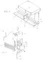
- Figure 1 is a perspective view of a device which is useful for practicing the methods of the present invention:
- Figure 2 is a perspective view of a voice coil actuator from the device shown in Figure 1 with portions broken away for clarity;
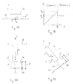
- Figure 3A is a free body diagram of a block resting on a surface:
- Figure 3B is a graph showing the relationship between static friction and kinetic friction;
- Figure 4A is a free body diagram of the probe assembly of the actuator shown in Figure 2 with the probe assembly in a vertical orientation;
- Figure 4B is a free body diagram of the probe assembly of the actuator shown in Figure 2 with the probe assembly in an angled orientation; and
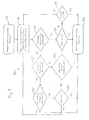
- Figure 5 is a logic flow chart of the steps used in practicing the methods of the present invention.
-
- Referring initially to Figure 1 a device for performing the methods of the present invention is shown and generally designated 10. As shown, the
device 10 includes a linear motor of a type similar to the one disclosed and claimed in U.S. Patent No. 5,446,323 which issued to Neff et al. for an invention entitled "Actuator with Translational and Rotational Control", and which is assigned to the same assignee as the present invention. - In Figure 2 the
actuator 12 is more clearly shown to include areciprocating coil 14 which surrounds amagnet 16. In a manner well known in the pertinent art, when an electrical current is passed through thecoil 14, a flux field is established which interacts with the magnetic flux field of themagnet 16. As is also well known, this interaction creates forces on thecoil 14. Depending on the amount and direction of current flow in thecoil 14, the magnitude and direction of the forces that are created on thecoil 14 can be controlled to move the coil. Thus, thecoil 14 can be made to reciprocate. If, as intended for the present invention, aprobe assembly 18 is connected directly to the coil, theprobe assembly 18 will move and reciprocate with thecoil 14. Furthermore, with proper reciprocation of theprobe assembly 18 by theactuator 12, and with a coordinated movement of theactuator 12 by the device 10 (such as is suggested in Figure 1 for movement ofactuator 12 to and from the position of actuator 12') theprobe assembly 18 can be operated to place acomponent 20 into proper position on awork surface 22. As can be easily appreciated, such action could be used to create anend product 24. - The present invention, however, it is not an assembly process per se. Instead, it is the control of contact forces between
probe assembly 18 andcomponent 20, and the subsequent contact force betweenprobe assembly 18 and/orcomponent 20 andwork surface 22 that is of concern. In order to appreciate the nature of the forces which act onprobe assembly 18, and thus the nature of the forces that are to be controlled in accordance with the methods of the present invention, a brief review of frictional forces will be helpful. To this end, consider Figure 3A wherein thebody 26 is shown to have a weight W and to be resting on asurface 28. - From basic equations of equilibrium it is known that, for a static equilibrium condition such as the condition shown in Figure 3A, the sum of forces in both the x and the y directions must equal zero. Thus, the weight W of
body 26 is equal to the normal force N. Static equilibrium equations also indicate that, for equilibrium in the x direction, the push/pull force P must be equal to the friction force F. The equation is:body 26 is in static equilibrium, F will vary directly with changes in P. However, just as P exceeds Fm, a transition push/pull force (Pt) is placed on thebody 26 and static conditions no longer pertain. At this point, under the influence of Pt, the condition ofbody 26 transitions from a static condition to a dynamic condition. Stated differently, the maximum static friction force Fm has been overcome and thebody 26 begins to move. Further, as also shown in Figure 3B, it happens that after thebody 26 begins to move, the kinetic friction force Fk is less than the maximum static friction force Fm. Due to this difference, the push/pull force Pt will cause thebody 26 to accelerate. Recall, F = ma . - With the above in mind, first consider the free body diagram of
probe assembly 18 as it is shown in Figure 4A. In this free body diagram, all of the forces which act on theprobe assembly 18 are shown for the specific condition when theprobe assembly 18 is stationary. More specifically, Figure 4A showsprobe assembly 18 while it is held vertically above thework surface 22 in an approach position preparatory to contact withwork surface 22. The forces acting onprobe assembly 18 in this condition are i) its weight W, ii) all friction forces which are represented by F, and iii) the activating push/pull force P. - Still referring to Figure 4A it will be appreciated that an equation of static equilibrium the
probe assembly 18 in the y direction will be: - For purposes of the present invention it is to be appreciated that the push/pull force P essentially represents the torque which is exerted on
probe assembly 18 by the interaction betweencoil 14 andmagnet 16. The friction forces F, then, is the sum of all other mechanical forces which combine to resist any reciprocal movement of theprobe assembly 18 inactuator 12. - Since
probe assembly 18 need not always be vertically oriented as shown in Figure 4A, consider also the more generalized free body diagram ofprobe assembly 18 that is shown in Figure 4B. By comparing Figure 4A with Figure 4B it will be seen that a change in the orientation of probe assembly from a vertical orientation (Figure 4A) to an angled (Figure 4B) causes a change in the direction that weight W acts onprobe assembly 18. This will also affect the magnitude of force P that is necessary to maintain static equilibrium. The point to be made is, that regardless of the orientation ofprobe assembly 18, several forces will continue to act in some way against theprobe assembly 18. For the specific condition shown in Figure 4B, the equation of static equilibrium forprobe assembly 18 in the x direction will be:coil 14 withmagnet 16, and the friction force F represents all forces which resist movement ofprobe assembly 18 onactuator 12. The angle is representative of the angle at which theprobe assembly 18 is oriented in the approach position relative to a horizontal orientation. For example, in Figure 4A, whenprobe assembly 18 is held vertically, the angle is equal to 90° and sin is equal to 1 . Thus, Eqn #2. - Referring now to Figure 5, the method of the present invention is shown as a logic flow chart and is generally designated 30. To begin
method 30, as indicated atbox 32, theprobe assembly 18 is placed at an approach position. More specifically, to accomplish this step ofmethod 30 theprobe assembly 18 is moved into the approach position by the action ofactuator 12. It may then, but not necessarily, be held stationary while in the approach position. As indicated above, the approach position can be arbitrarily selected by the operator. For purposes of discussion here, however, an approach position is selected such that theprobe assembly 18 is located at adistance 34 fromwork surface 22. Further, thedistance 34 is preferably much less than one millimeter. Thisdistance 34 is shown in both Figures 4A and 4B. -
Box 36 indicates that a push/pull force (P) is to be applied to theprobe assembly 18 while it is in the approach position. Further, the purpose of this push/pull force P is to advance theprobe assembly 18 toward thework surface 22. The application of push/pull force (P), however, requires an appreciation of all of the other forces which are acting onprobe assembly 18. Recall, that for a static equilibrium condition, the push/pull force P (i.e. torque from actuator 12) could be varied through a range. This could be done so long as the friction force F did not exceed the maximum static friction force Fm. With this in mind,box 36 contemplates that the push/pull force P will be appropriately changed through the operation ofactuator 12 to transition theprobe assembly 18 from a static to a dynamic condition, i.e. P will be adjusted until P is equal to Pt. Specifically, this transition involves a change from the static stationary condition ofprobe assembly 18 at the approach position, into a dynamic condition wherein theprobe assembly 18 advances towardwork surface 22 along apath 38. For example, consider the condition ofprobe assembly 18 as depicted in Figure 4A. Weight W will, of course, remain constant. However, according to Eqn #2, if the sum of the push/pull force P and the friction forces F is less than the weight W, then the imbalance of forces onprobe assembly 18 will disrupt its static equilibrium condition and cause theprobe assembly 18 to accelerate towardwork surface 22. As a practical matter, it happens that the only force in this example which is controllable by the operator ofmethod 30 is the push/pull force P. Thus, the step inmethod 30 that is contemplated bybox 36 is the establishment of a threshold force Pt that is of sufficient magnitude, and in the proper direction, to transitionprobe assembly 18 from its static condition at the approach position into a dynamic condition. With this transition, theprobe assembly 18 will advance toward thework surface 22. - It is to be appreciated that
probe assembly 18 need not be actually stopped at the approach position during each cycle in the execution ofmethod 30. Indeed, as contemplated by the present invention, if a value for Pt has been previously established,probe assembly 18 can be in continuous motion as it passes through the approach position. To initially establish the value for a push/pull force Pt, theprobe assembly 18 first needs to be stopped (i.e. placed in a static condition). The torque fromactuator 12 is then varied to empirically determine a value for Pt. - Returning for the moment to Figure 2, it will be seen that the
actuator 12 of the present invention includes anencoder 40. As intended for the present invention, theencoder 40 can be of any type of position feedback sensor that is well known in the pertinent art. Here, but only for purposes of example, an optical encoder is considered, Thus, theencoder 40 includes anoptical scanner 42 which is operationally associated with ascale 44 that is mounted on theprobe assembly 18 for movement therewith. Additionally, atimer 46 is included in theoptical encoder 40. - Through methods well known to any skilled artisan, by monitoring the
scale 44, the position ofprobe assembly 18 relative to actuator 12 can be determined. Consequently, the position (S) ofprobe assembly 18 alongpath 38 can also be determined. Albeit, approximately. Further, by comparing changes in the position S ofprobe assembly 18 with predetermined intervals of time that are established by the timer 46 (i.e. dS/dt), the velocity (V) ofprobe assembly 18 alongpath 38 can also be determined. Still further, by monitoring the time rate of change in its velocity V (i.e. dV/dt),the accelerations (a) ofprobe assembly 18 alongpath 38 can be determined. - Returning now to Figure 5, after the push/pull force P has been applied to the
probe assembly 18,box 48 ofmethod 30 shows that an inquiry is made as to whether the velocity V ofprobe assembly 18 is monitored. If the answer to this inquiry is yes,box 50 then indicates that the next question concerns whether this velocity is equal to zero. If so,box 52 shows that a soft contact has been made. For purposes of identification and differentiation, this mode of operation inmethod 30 is sometimes referred to herein as the velocity mode. - A refinement of the velocity mode of operation for the present invention can be made by maintaining the velocity at a constant magnitude. One advantage of this refinement is that it allows for compensation of small changes in the friction forces F which oppose advancement of the
probe assembly 18. There are many well known feedback variations which could be used for this purpose. For each variation, however, it is necessary to monitor both the velocity and the torque value for the push/pull force P which is necessary to maintain the constant velocity. Further, once the force P exceed a predetermined value, it must be determined or concluded that soft contact with the work surface has occurred. Otherwise, an excessive force P could be called upon which could easily damage the work surface. - Going back to
box 50, it can be seen that if the velocity V ofprobe assembly 18 is not monitored for a zero value but is, instead, monitored for changes to determine accelerations of theprobe assembly 18, thenbox 54 shows that an acceleration onprobe assembly 18 which is above a predetermined absolute value will indicate a soft contact of theprobe assembly 18 withwork surface 22. This mode of operation inmethod 30 is sometimes referred to as the acceleration control mode. - Returning to
box 48 ofmethod 30, if the velocity V ofprobe assembly 18 is not specifically monitored, the inquiry is made atbox 55 as to whether the position S ofprobe assembly 18 is monitored. If so,box 56 inquires as to whether theprobe assembly 18 has moved along thepath 38 through a distance D. To determine distance D, it is first necessary to make an estimate of thedistance 34 between thework surface 22 and theprobe assembly 18. This estimate is made with theprobe assembly 18 in the approach position and can be incorporated into the set up ofdevice 10. Regardless what the estimate fordistance 34 may be, an incremental overshoot distance 58 (see Figures 4A and 4B) is added to thedistance 34 to establish distance D. For purposes of the present invention, theovershoot distance 58 can be on the order of about one ten thousandth of an inch (0.0001 in.), and preferably even less. Soft contact of theprobe assembly 18 withwork surface 22 will then be determined as having occurred when theprobe assembly 18 has traveled alongpath 38 through the distance D. An important consideration in this mode of operation formethod 30 is that theencoder 40 can accurately measure the distances that have been traveled byprobe assembly 18 alongpath 38. Theencoder 40, however, does not measure thedistance 34 that is characteristic of the approach position. This mode of operation is sometimes referred to as the position control mode. - It will be appreciated that the position control mode can also be used, in conjunction with a clock (not shown) which will measure the time which has transpired after the
probe assembly 18 has been monitored as being in a particular position. With this knowledge, it is also contemplated by the present invention that the passage of time afterprobe assembly 18 leaves the approach position can be used to determine whether soft contact has occurred. In this operational mode, theprobe assembly 18 is established in the approach position, it is then released under the influence of push/pull force Pt, and after the passage of a predetermined time interval soft contact is accepted as having occurred. - Figure 5 also indicates at
box 60 that the landing force L (i.e. the actual force at contact betweenprobe assembly 18 and work surface 22) can be monitored to determine whether theprobe assembly 18 has made soft contact with thework surface 22. This mode of operation requires the use of aload sensor 62 which can be mounted onprobe assembly 18, such as is shown in Figure 2. For purposes of the present invention,load sensor 62 can be of any type well known in the pertinent art, such as a type manufactured by Futek. As indicated bybox 64 ofmethod 30, when aload sensor 62 is incorporated intoprobe assembly 18, a soft contact between theprobe assembly 18 and thework surface 22 will be determined upon the activation ofload sensor 62. Stated differently, the presence of a landing force L will activate theload sensor 62 to determine soft contact. -
Method 30 also indicates that soft landing can be determined when no measurable parameters of the movement ofprobe assembly 18 are specifically monitored. For this mode or operation, the inquiries atboxes probe assembly 18 towardwork surface 22. Recall, for all of the modes discussed here, including the basic case, the push/pull force P is applied to theprobe assembly 18 while theprobe assembly 18 is in the approach position. Further, the push/pull force P is established as being the force P, with appropriate magnitude and direction, which is just necessary to transition theprobe assembly 18 from a static condition to a dynamic condition. - Further to the above, the
method 30 of the present invention contemplates an ability to selectively use a particular mode of operation. This selection will, of course, depend upon the needs and desires of the operator. Further, regardless which mode of operation is to be used, the methods of the present invention contemplate that soft contact can be made with landing forces of below fifty grams (50 gm), and conceivable as low as approximately one hundredth of a gram (0.01 gm). Further, after soft contact has been determined, it is also within the contemplation of the present invention that the push/pull force P can be appropriately altered to maintain the static contact force between theprobe assembly 18 and thework surface 22 at a value equal to, or nearly equal to, the soft contact landing force L. On the other hand, push/pull force P can be altered after soft contact to create whatever force is desired betweenprobe assembly 18 andwork surface 22.
Claims (21)
- A method for moving a machine part into soft contact with a work surface which comprises the steps of:moving a machine part (18) into an approach position at a predetermined distance (34) from a work surface (22);applying a threshold force on the machine part (18) at the approach position to transition the machine part (18) from a static condition to a dynamic condition and to advance the machine part (18) along a substantially linear path (38) from the approach position to the work surface (22); selecting a measurable parameter of the machine part (18) that is characteristic of the advancement of the machine part (18) along said path (38); providing an encoder for monitoring the measurable parameter to monitor the advancement of the machine part (18) along the substantially linear path (38) by fixing a position and travel distance of the machine part (18) from the approach position along said path (38); characterised in that the machine part (18) is a probe assembly, monitoring the measurable parameter includes comparing said travel distance to said predetermined distance (34) to determine soft contact of the probe assembly (18) with the work surface (22) when the travel distance exceeds the predetermined distance (34), and the threshold force on the probe assembly advances the probe assembly (18) through the predetermined distance (34).
- A method as claimed in claim 1 wherein the measurable parameter is the velocity of advancement of the probe assembly (18).
- A method as claimed in claim 2 wherein soft contact of the probe assembly (18) with the work surface (22) is determined when said velocity is equal to zero.
- A method as claimed in claim 1 wherein the measurable parameter is the acceleration of advancement of said probe assembly (18).
- A method as claimed in claim 4 wherein soft contact of the probe assembly (18) with the work surface (22) is determined when said acceleration exceeds a predetermined value.
- A method as claimed in claim 1 wherein the measurable parameter is the travel distance of probe assembly (18) along said path (38).
- A method as claimed in claim 6 wherein soft contact of the probe assembly (18) with the work surface (22) is determined when said travel distance exceeds the predetermined distance (34).
- A method as claimed in claim 7 wherein the measurable parameter of the probe assembly (18) further includes time and soft contact of the probe assembly (18) with the work surface (22) is determined after the passage of a predetermined time interval.
- A method as claimed in claim 1 wherein the measurable parameter of the probe assembly (18) is a reactive force on the probe assembly (18) during advancement of the probe assembly (18) along said path (38) and soft contact of the probe assembly (18) with the work surface (22) is determined when said reactive force plus said threshold force on the probe assembly (18) are opposite and are at least equal to the weight of the probe assembly (18).
- A method as claimed in claim 9 further including the step of attaching a load sensor (62) to the probe assembly (18) for contact with the work surface (22) and for measuring the reactive force on the probe assembly (18).
- A method as claimed in claim 1 wherein the monitoring step is accomplished by maintaining the threshold force for advancing the probe assembly (18) at a substantially constant magnitude.
- A method as claimed in claim 1 further comprising the step of applying an additional force to the probe assembly (18) to urge the probe assembly (18) against the work surface (22) while the probe assembly (18) is in contact with the work surface (18).
- A method as claimed in claim 1 wherein said path (38) is substantially perpendicular to the work surface (22).
- A method as claimed in claim 1 wherein the predetermined distance (34) is less than approximately one millimeter.
- A method as claimed in claim 1 wherein the threshold force is less than five hundred grams.
- A method as claimed in claim 1 wherein the threshold force is less than the weight of the probe assembly (18), and the threshold force is applied to the probe assembly (18) in a direction substantially opposite to the weight of the probe assembly (18).
- A method as claimed in Claim 1 further including the step of applying a first force to move the probe assembly (18) into the approach position.
- A method as claimed in Claim 17 wherein the first force is gravity.
- A device for moving a machine part into soft contact with a work surface which comprises:characterised in that the machine part (18) is a probe assembly, the monitoring means includes means (44) for comparing said travel distance to said predetermined distance (34) to determine soft contact of the probe assembly (18) with the work surface (22) when the travel distance exceeds the predetermined distance (34), and the force generating means applies a force on the probe assembly (18) to advance the probe assembly (18) through the predetermined distance (34).a directing means for placing a machine part (18) into an approach position at a predetermined distance (34) from a work surface (22);a force generating means for applying a force on the machine part (18) at the approach position to advance the machine part (18) along a substantially linear path (38) from the approach position to the work surface (22);means for selecting a measurable parameter of the machine part (18) that is characteristic of the advancement of the machine part (18) along said path (38); means for monitoring the measurable parameter to monitor the advancement of the machine part (18) along the substantially linear path (38), the monitoring means comprising; an encoder (40) for fixing a position and a travel distance of the machine part (18) from the approach position along said path (38);
- A device as recited in claim 19 wherein the monitoring means further comprises:a timer (46) for corresponding the change of position of the probe (18) with a preselected time interval to ascertain a velocity for the advancement of the probe assembly (18) along said path (38); andmeans for determining soft contact of the probe assembly (18) with the work surface (22) as being when said velocity is equal to zero.
- A device as recited in claim 20 wherein the monitoring means further comprises:an electronic comparator for measuring changes in the velocity of advancement of the probe assembly (18) along said path (38) to determine an acceleration of the probe assembly (18); andmeans for determining soft contact of the probe assembly with the work surface (22) as being when the acceleration of the probe assembly (18) exceeds a threshold absolute value.
Applications Claiming Priority (2)
| Application Number | Priority Date | Filing Date | Title |
|---|---|---|---|
| US587878 | 1996-01-11 | ||
| US08/587,878 US5952589A (en) | 1996-01-11 | 1996-01-11 | Soft landing method for probe assembly |
Publications (2)
| Publication Number | Publication Date |
|---|---|
| EP0784252A1 EP0784252A1 (en) | 1997-07-16 |
| EP0784252B1 true EP0784252B1 (en) | 1999-12-29 |
Family
ID=24351554
Family Applications (1)
| Application Number | Title | Priority Date | Filing Date |
|---|---|---|---|
| EP96307633A Expired - Lifetime EP0784252B1 (en) | 1996-01-11 | 1996-10-22 | Soft landing method for probe assembly |
Country Status (4)
| Country | Link |
|---|---|
| US (1) | US5952589A (en) |
| EP (1) | EP0784252B1 (en) |
| JP (1) | JP3472671B2 (en) |
| DE (1) | DE69605890T2 (en) |
Families Citing this family (21)
| Publication number | Priority date | Publication date | Assignee | Title |
|---|---|---|---|---|
| JPH1195821A (en) * | 1997-09-18 | 1999-04-09 | Mitsubishi Electric Corp | Contact detection method and device |
| DE19844428B4 (en) | 1998-09-28 | 2004-05-13 | Atg Test Systems Gmbh & Co.Kg | Test probe for a finger tester, a method for driving a test probe, finger tester for testing printed circuit boards and a method for testing printed circuit boards with a finger tester |
| US7259552B2 (en) | 2002-05-31 | 2007-08-21 | Siemens Power Generation, Inc. | Wear monitor for turbo-machine |
| US20050234565A1 (en) * | 2004-04-01 | 2005-10-20 | Systems, Machines, Automation Components, Corporation | Programmable control system for automated actuator operation |
| US20060271420A1 (en) * | 2005-05-27 | 2006-11-30 | Peter Anselmann | System and method for performing capacity checks and resource scheduling within a supply chain management system |
| JP2007007716A (en) * | 2005-07-04 | 2007-01-18 | Fanuc Ltd | Collision deciding device and collision deciding system for die cushion mechanism |
| JP4909548B2 (en) * | 2005-09-01 | 2012-04-04 | 株式会社ミツトヨ | Surface shape measuring device |
| DE112008000274T5 (en) | 2007-01-26 | 2009-12-17 | SMAC, Inc., Carlsbad | Combination of a pneumatic and electric linear actuator |
| US9731418B2 (en) * | 2008-01-25 | 2017-08-15 | Systems Machine Automation Components Corporation | Methods and apparatus for closed loop force control in a linear actuator |
| US9748824B2 (en) | 2012-06-25 | 2017-08-29 | Systems Machine Automation Components Corporation | Linear actuator with moving central coil and permanent side magnets |
| US9375848B2 (en) | 2012-06-25 | 2016-06-28 | Systems Machine Automation Components Corporation | Robotic finger |
| JP5963755B2 (en) | 2010-09-23 | 2016-08-03 | システムズ マシーンズ オートメーション コンポーネンツ コーポレイション | Low cost multi-coil linear actuator |
| US10807248B2 (en) | 2014-01-31 | 2020-10-20 | Systems, Machines, Automation Components Corporation | Direct drive brushless motor for robotic finger |
| US9871435B2 (en) | 2014-01-31 | 2018-01-16 | Systems, Machines, Automation Components Corporation | Direct drive motor for robotic finger |
| JP6238869B2 (en) | 2014-10-28 | 2017-11-29 | アズビル株式会社 | Touch control device |
| US10429211B2 (en) | 2015-07-10 | 2019-10-01 | Systems, Machines, Automation Components Corporation | Apparatus and methods for linear actuator with piston assembly having an integrated controller and encoder |
| US10215802B2 (en) * | 2015-09-24 | 2019-02-26 | Systems, Machines, Automation Components Corporation | Magnetically-latched actuator |
| US10865085B1 (en) * | 2016-04-08 | 2020-12-15 | Systems, Machines, Automation Components Corporation | Methods and apparatus for applying a threaded cap using a linear rotary actuator |
| US10675723B1 (en) * | 2016-04-08 | 2020-06-09 | Systems, Machines, Automation Components Corporation | Methods and apparatus for inserting a threaded fastener using a linear rotary actuator |
| US10205355B2 (en) | 2017-01-03 | 2019-02-12 | Systems, Machines, Automation Components Corporation | High-torque, low-current brushless motor |
| US11804745B2 (en) | 2020-02-07 | 2023-10-31 | Systems, Machines, Automation Components Corporation | Multi-layer printed coil arrangement having variable-pitch printed coils |
Citations (1)
| Publication number | Priority date | Publication date | Assignee | Title |
|---|---|---|---|---|
| US4547847A (en) * | 1982-06-09 | 1985-10-15 | Amca International Corporation | Adaptive control for machine tools |
Family Cites Families (24)
| Publication number | Priority date | Publication date | Assignee | Title |
|---|---|---|---|---|
| NL7114104A (en) * | 1971-10-13 | 1973-04-17 | ||
| US3743093A (en) * | 1972-01-20 | 1973-07-03 | A Klancnik | Sorting machines |
| US3987551A (en) * | 1973-01-06 | 1976-10-26 | Tesa S.A. | Apparatus for measuring continuous or discontinuous surfaces |
| US4215301A (en) * | 1978-10-10 | 1980-07-29 | Hewlett-Packard Company | Digital servo positioning circuit |
| US4484118A (en) * | 1981-08-29 | 1984-11-20 | Toshiba Kikai Kabushiki Kaisha | Method and apparatus for measuring a workpiece |
| US4498023A (en) * | 1983-10-31 | 1985-02-05 | Motorola, Inc. | Voice coil linear motor with integral capacitor |
| CA1276710C (en) * | 1983-11-30 | 1990-11-20 | Kazuo Asakawa | Robot force controlling system |
| US4575652A (en) * | 1984-09-27 | 1986-03-11 | Synektron Corporation | Permanent magnet motor having high starting torque and narrowly-defined detent zones |
| FR2600001B1 (en) * | 1986-06-11 | 1988-09-09 | Meseltron Sa | DEVICE FOR CONTROLLING THE FEED SPEED OF A TOOL TOWARDS A WORKPIECE |
| JPS62292328A (en) * | 1986-06-12 | 1987-12-19 | Matsushita Electric Ind Co Ltd | How to install parts |
| US4750272A (en) * | 1986-11-06 | 1988-06-14 | Kearney & Trecker Corporation | Tool measuring device employing gap width detection |
| US4857816A (en) * | 1987-02-05 | 1989-08-15 | Joseph Rogozinski | Precise positioning apparatus |
| US4784539A (en) * | 1987-05-18 | 1988-11-15 | Manuflex Corporation | Tool communications method |
| DE3831974A1 (en) * | 1988-09-21 | 1990-03-29 | Wegu Messtechnik | Contact probe (sensor) |
| US5691461A (en) * | 1990-08-16 | 1997-11-25 | Isis Pharmaceuticals, Inc. | Oligonucleotides inhibiting candida germ tube formation |
| US5399983A (en) * | 1991-08-08 | 1995-03-21 | Tokyo Electron Yamanashi Limited | Probe apparatus |
| US5175456A (en) * | 1991-09-25 | 1992-12-29 | Systems, Machines, Automation Components Corp. | Workpiece transporter |
| US5310064A (en) * | 1991-09-25 | 1994-05-10 | Systems, Machines, Automation Components, Corp. | Method and apparatus for sorting component parts of an assembly process |
| US5446323A (en) * | 1991-09-25 | 1995-08-29 | Systems, Machines, Automation Components Corporation | Actuator with translational and rotational control |
| US5315189A (en) * | 1991-09-25 | 1994-05-24 | Systems, Machines, Automation Corporation | Actuator with translational and rotational control |
| US5317222A (en) * | 1991-09-25 | 1994-05-31 | Systems, Machines, Automation Components Corp. | Workpiece transporter device with replaceable grip |
| US5430360A (en) * | 1993-04-30 | 1995-07-04 | Kohler General Corporation | Multiple head positioning apparatus for woodworking machine and the like |
| US5414620A (en) * | 1993-08-09 | 1995-05-09 | Honeywell Inc. | Synthetic friction algorithm for a hand control element |
| US5517190A (en) * | 1994-02-03 | 1996-05-14 | Gunn; Colin N. | Physical measurement from changes in reactance |
-
1996
- 1996-01-11 US US08/587,878 patent/US5952589A/en not_active Expired - Lifetime
- 1996-10-22 EP EP96307633A patent/EP0784252B1/en not_active Expired - Lifetime
- 1996-10-22 DE DE69605890T patent/DE69605890T2/en not_active Expired - Lifetime
- 1996-12-25 JP JP34604896A patent/JP3472671B2/en not_active Expired - Lifetime
Patent Citations (1)
| Publication number | Priority date | Publication date | Assignee | Title |
|---|---|---|---|---|
| US4547847A (en) * | 1982-06-09 | 1985-10-15 | Amca International Corporation | Adaptive control for machine tools |
Also Published As
| Publication number | Publication date |
|---|---|
| EP0784252A1 (en) | 1997-07-16 |
| JPH09311724A (en) | 1997-12-02 |
| DE69605890T2 (en) | 2000-08-03 |
| US5952589A (en) | 1999-09-14 |
| DE69605890D1 (en) | 2000-02-03 |
| JP3472671B2 (en) | 2003-12-02 |
Similar Documents
| Publication | Publication Date | Title |
|---|---|---|
| US5952589A (en) | Soft landing method for probe assembly | |
| EP1437637B1 (en) | Servomotor controller | |
| EP0566741B1 (en) | Abnormal load detecting method | |
| Mallon et al. | Friction compensation in a controlled one-link robot using a reduced-order observer | |
| Altintas | Prediction of cutting forces and tool breakage in milling from feed drive current measurements | |
| Futami et al. | Nanometer positioning and its micro-dynamics | |
| EP0585400B1 (en) | Active vibration control device | |
| US6499649B2 (en) | Friction stir welding apparatus | |
| EP1710643B1 (en) | NC machine tool and method of controlling NC machine tool | |
| KR0144650B1 (en) | Method of detecting and regulating load on servomotor | |
| EP1993007B1 (en) | Control method and controller of positioning mechanism | |
| EP0881044A1 (en) | Robot controller | |
| JP2665984B2 (en) | Collision detection method using disturbance estimation observer | |
| EP0065993B1 (en) | Copy cam driving device for machine tool | |
| CN109085802B (en) | Control device for motor | |
| Renton et al. | Motion control for linear motor feed drives in advanced machine tools | |
| Kakinuma et al. | Sensor-less micro-tool contact detection for ultra-precision machine tools utilizing the disturbance observer technique | |
| US5742144A (en) | Backlash compensation method for semi-closed-loop type servo control | |
| JP3211406B2 (en) | Vibration suppression control method and velocity pattern calculation method and apparatus using the same | |
| Yamada et al. | Integrated chatter monitoring based on sensorless cutting force/torque estimation in parallel turning | |
| Kawaji et al. | Control of cutting torque in the drilling process using disturbance observer | |
| EP0231245B1 (en) | Machine tools | |
| JPH06131050A (en) | Method for detecting collision of movable part driven by servo motor | |
| US6122998A (en) | Force control method for a bar feeder of a lathe | |
| Hanson et al. | Reducing cutting force induced bore cylindricity errors by learning control and variable depth of cut machining |
Legal Events
| Date | Code | Title | Description |
|---|---|---|---|
| PUAI | Public reference made under article 153(3) epc to a published international application that has entered the european phase |
Free format text: ORIGINAL CODE: 0009012 |
|
| AK | Designated contracting states |
Kind code of ref document: A1 Designated state(s): CH DE ES FR GB IT LI NL |
|
| 17P | Request for examination filed |
Effective date: 19971114 |
|
| 17Q | First examination report despatched |
Effective date: 19980119 |
|
| GRAG | Despatch of communication of intention to grant |
Free format text: ORIGINAL CODE: EPIDOS AGRA |
|
| GRAG | Despatch of communication of intention to grant |
Free format text: ORIGINAL CODE: EPIDOS AGRA |
|
| GRAH | Despatch of communication of intention to grant a patent |
Free format text: ORIGINAL CODE: EPIDOS IGRA |
|
| GRAH | Despatch of communication of intention to grant a patent |
Free format text: ORIGINAL CODE: EPIDOS IGRA |
|
| GRAA | (expected) grant |
Free format text: ORIGINAL CODE: 0009210 |
|
| AK | Designated contracting states |
Kind code of ref document: B1 Designated state(s): CH DE ES FR GB IT LI NL |
|
| PG25 | Lapsed in a contracting state [announced via postgrant information from national office to epo] |
Ref country code: LI Free format text: LAPSE BECAUSE OF FAILURE TO SUBMIT A TRANSLATION OF THE DESCRIPTION OR TO PAY THE FEE WITHIN THE PRESCRIBED TIME-LIMIT Effective date: 19991229 Ref country code: IT Free format text: LAPSE BECAUSE OF FAILURE TO SUBMIT A TRANSLATION OF THE DESCRIPTION OR TO PAY THE FEE WITHIN THE PRESCRIBED TIME-LIMIT;WARNING: LAPSES OF ITALIAN PATENTS WITH EFFECTIVE DATE BEFORE 2007 MAY HAVE OCCURRED AT ANY TIME BEFORE 2007. THE CORRECT EFFECTIVE DATE MAY BE DIFFERENT FROM THE ONE RECORDED. Effective date: 19991229 Ref country code: ES Free format text: THE PATENT HAS BEEN ANNULLED BY A DECISION OF A NATIONAL AUTHORITY Effective date: 19991229 Ref country code: CH Free format text: LAPSE BECAUSE OF FAILURE TO SUBMIT A TRANSLATION OF THE DESCRIPTION OR TO PAY THE FEE WITHIN THE PRESCRIBED TIME-LIMIT Effective date: 19991229 |
|
| REG | Reference to a national code |
Ref country code: CH Ref legal event code: EP |
|
| REF | Corresponds to: |
Ref document number: 69605890 Country of ref document: DE Date of ref document: 20000203 |
|
| ET | Fr: translation filed | ||
| REG | Reference to a national code |
Ref country code: CH Ref legal event code: PL |
|
| PGFP | Annual fee paid to national office [announced via postgrant information from national office to epo] |
Ref country code: NL Payment date: 20001026 Year of fee payment: 5 |
|
| PLBE | No opposition filed within time limit |
Free format text: ORIGINAL CODE: 0009261 |
|
| STAA | Information on the status of an ep patent application or granted ep patent |
Free format text: STATUS: NO OPPOSITION FILED WITHIN TIME LIMIT |
|
| 26N | No opposition filed | ||
| REG | Reference to a national code |
Ref country code: GB Ref legal event code: IF02 |
|
| PG25 | Lapsed in a contracting state [announced via postgrant information from national office to epo] |
Ref country code: NL Free format text: LAPSE BECAUSE OF NON-PAYMENT OF DUE FEES Effective date: 20020501 |
|
| NLV4 | Nl: lapsed or anulled due to non-payment of the annual fee |
Effective date: 20020501 |
|
| PGFP | Annual fee paid to national office [announced via postgrant information from national office to epo] |
Ref country code: GB Payment date: 20091021 Year of fee payment: 14 Ref country code: FR Payment date: 20091029 Year of fee payment: 14 |
|
| GBPC | Gb: european patent ceased through non-payment of renewal fee |
Effective date: 20101022 |
|
| PG25 | Lapsed in a contracting state [announced via postgrant information from national office to epo] |
Ref country code: FR Free format text: LAPSE BECAUSE OF NON-PAYMENT OF DUE FEES Effective date: 20101102 |
|
| REG | Reference to a national code |
Ref country code: FR Ref legal event code: ST Effective date: 20110630 |
|
| PG25 | Lapsed in a contracting state [announced via postgrant information from national office to epo] |
Ref country code: GB Free format text: LAPSE BECAUSE OF NON-PAYMENT OF DUE FEES Effective date: 20101022 |
|
| PGFP | Annual fee paid to national office [announced via postgrant information from national office to epo] |
Ref country code: DE Payment date: 20151013 Year of fee payment: 20 |
|
| REG | Reference to a national code |
Ref country code: DE Ref legal event code: R071 Ref document number: 69605890 Country of ref document: DE |