EP0783914B1 - Filter element for air cleaner - Google Patents
Filter element for air cleaner Download PDFInfo
- Publication number
- EP0783914B1 EP0783914B1 EP97100194A EP97100194A EP0783914B1 EP 0783914 B1 EP0783914 B1 EP 0783914B1 EP 97100194 A EP97100194 A EP 97100194A EP 97100194 A EP97100194 A EP 97100194A EP 0783914 B1 EP0783914 B1 EP 0783914B1
- Authority
- EP
- European Patent Office
- Prior art keywords
- filter
- filter medium
- filter element
- basic
- filtration
- Prior art date
- Legal status (The legal status is an assumption and is not a legal conclusion. Google has not performed a legal analysis and makes no representation as to the accuracy of the status listed.)
- Expired - Lifetime
Links
- 238000001914 filtration Methods 0.000 claims description 75
- 229920003002 synthetic resin Polymers 0.000 claims description 32
- 239000000057 synthetic resin Substances 0.000 claims description 32
- 239000000463 material Substances 0.000 claims description 14
- 238000005245 sintering Methods 0.000 claims description 9
- 239000000843 powder Substances 0.000 description 13
- 238000000465 moulding Methods 0.000 description 9
- 230000002093 peripheral effect Effects 0.000 description 9
- 238000010276 construction Methods 0.000 description 8
- 230000004048 modification Effects 0.000 description 8
- 238000012986 modification Methods 0.000 description 8
- 230000003247 decreasing effect Effects 0.000 description 6
- 238000000034 method Methods 0.000 description 6
- 230000008569 process Effects 0.000 description 6
- -1 for example Polymers 0.000 description 4
- 238000004519 manufacturing process Methods 0.000 description 4
- 230000009467 reduction Effects 0.000 description 4
- 238000003466 welding Methods 0.000 description 4
- 239000002245 particle Substances 0.000 description 3
- 229920005989 resin Polymers 0.000 description 3
- 239000011347 resin Substances 0.000 description 3
- 239000004743 Polypropylene Substances 0.000 description 2
- 238000002485 combustion reaction Methods 0.000 description 2
- 239000000706 filtrate Substances 0.000 description 2
- 230000007246 mechanism Effects 0.000 description 2
- 239000004745 nonwoven fabric Substances 0.000 description 2
- 229920001155 polypropylene Polymers 0.000 description 2
- 238000007789 sealing Methods 0.000 description 2
- 230000001419 dependent effect Effects 0.000 description 1
- 238000011161 development Methods 0.000 description 1
- 230000018109 developmental process Effects 0.000 description 1
- 239000013013 elastic material Substances 0.000 description 1
- 238000012423 maintenance Methods 0.000 description 1
- 238000002844 melting Methods 0.000 description 1
- 230000008018 melting Effects 0.000 description 1
- 239000004033 plastic Substances 0.000 description 1
- 238000005096 rolling process Methods 0.000 description 1
- 239000012815 thermoplastic material Substances 0.000 description 1
- 238000005406 washing Methods 0.000 description 1
Images




Classifications
-
- B—PERFORMING OPERATIONS; TRANSPORTING
- B01—PHYSICAL OR CHEMICAL PROCESSES OR APPARATUS IN GENERAL
- B01D—SEPARATION
- B01D39/00—Filtering material for liquid or gaseous fluids
- B01D39/14—Other self-supporting filtering material ; Other filtering material
- B01D39/16—Other self-supporting filtering material ; Other filtering material of organic material, e.g. synthetic fibres
- B01D39/1638—Other self-supporting filtering material ; Other filtering material of organic material, e.g. synthetic fibres the material being particulate
- B01D39/1653—Other self-supporting filtering material ; Other filtering material of organic material, e.g. synthetic fibres the material being particulate of synthetic origin
- B01D39/1661—Other self-supporting filtering material ; Other filtering material of organic material, e.g. synthetic fibres the material being particulate of synthetic origin sintered or bonded
-
- B—PERFORMING OPERATIONS; TRANSPORTING
- B01—PHYSICAL OR CHEMICAL PROCESSES OR APPARATUS IN GENERAL
- B01D—SEPARATION
- B01D46/00—Filters or filtering processes specially modified for separating dispersed particles from gases or vapours
- B01D46/10—Particle separators, e.g. dust precipitators, using filter plates, sheets or pads having plane surfaces
-
- B—PERFORMING OPERATIONS; TRANSPORTING
- B01—PHYSICAL OR CHEMICAL PROCESSES OR APPARATUS IN GENERAL
- B01D—SEPARATION
- B01D46/00—Filters or filtering processes specially modified for separating dispersed particles from gases or vapours
- B01D46/24—Particle separators, e.g. dust precipitators, using rigid hollow filter bodies
- B01D46/2403—Particle separators, e.g. dust precipitators, using rigid hollow filter bodies characterised by the physical shape or structure of the filtering element
- B01D46/2418—Honeycomb filters
- B01D46/2451—Honeycomb filters characterized by the geometrical structure, shape, pattern or configuration or parameters related to the geometry of the structure
- B01D46/2455—Honeycomb filters characterized by the geometrical structure, shape, pattern or configuration or parameters related to the geometry of the structure of the whole honeycomb or segments
-
- B—PERFORMING OPERATIONS; TRANSPORTING
- B01—PHYSICAL OR CHEMICAL PROCESSES OR APPARATUS IN GENERAL
- B01D—SEPARATION
- B01D46/00—Filters or filtering processes specially modified for separating dispersed particles from gases or vapours
- B01D46/24—Particle separators, e.g. dust precipitators, using rigid hollow filter bodies
- B01D46/2403—Particle separators, e.g. dust precipitators, using rigid hollow filter bodies characterised by the physical shape or structure of the filtering element
- B01D46/2418—Honeycomb filters
- B01D46/2451—Honeycomb filters characterized by the geometrical structure, shape, pattern or configuration or parameters related to the geometry of the structure
- B01D46/247—Honeycomb filters characterized by the geometrical structure, shape, pattern or configuration or parameters related to the geometry of the structure of the cells
-
- B—PERFORMING OPERATIONS; TRANSPORTING
- B01—PHYSICAL OR CHEMICAL PROCESSES OR APPARATUS IN GENERAL
- B01D—SEPARATION
- B01D46/00—Filters or filtering processes specially modified for separating dispersed particles from gases or vapours
- B01D46/24—Particle separators, e.g. dust precipitators, using rigid hollow filter bodies
- B01D46/2403—Particle separators, e.g. dust precipitators, using rigid hollow filter bodies characterised by the physical shape or structure of the filtering element
- B01D46/2418—Honeycomb filters
- B01D46/2451—Honeycomb filters characterized by the geometrical structure, shape, pattern or configuration or parameters related to the geometry of the structure
- B01D46/2474—Honeycomb filters characterized by the geometrical structure, shape, pattern or configuration or parameters related to the geometry of the structure of the walls along the length of the honeycomb
-
- B—PERFORMING OPERATIONS; TRANSPORTING
- B01—PHYSICAL OR CHEMICAL PROCESSES OR APPARATUS IN GENERAL
- B01D—SEPARATION
- B01D46/00—Filters or filtering processes specially modified for separating dispersed particles from gases or vapours
- B01D46/24—Particle separators, e.g. dust precipitators, using rigid hollow filter bodies
- B01D46/2403—Particle separators, e.g. dust precipitators, using rigid hollow filter bodies characterised by the physical shape or structure of the filtering element
- B01D46/2418—Honeycomb filters
- B01D46/2451—Honeycomb filters characterized by the geometrical structure, shape, pattern or configuration or parameters related to the geometry of the structure
- B01D46/2486—Honeycomb filters characterized by the geometrical structure, shape, pattern or configuration or parameters related to the geometry of the structure characterised by the shapes or configurations
-
- F—MECHANICAL ENGINEERING; LIGHTING; HEATING; WEAPONS; BLASTING
- F02—COMBUSTION ENGINES; HOT-GAS OR COMBUSTION-PRODUCT ENGINE PLANTS
- F02M—SUPPLYING COMBUSTION ENGINES IN GENERAL WITH COMBUSTIBLE MIXTURES OR CONSTITUENTS THEREOF
- F02M35/00—Combustion-air cleaners, air intakes, intake silencers, or induction systems specially adapted for, or arranged on, internal-combustion engines
- F02M35/02—Air cleaners
- F02M35/024—Air cleaners using filters, e.g. moistened
Definitions
- the present invention relates to a filter element according to the preamble of claim 1 or 7 to be incorporated into an air cleaner which filtrates or purifies air to be sucked into an internal combustion engine of an automobile.
- a conventional typical filter element for an air cleaner of an automobile is constituted generally of a filter medium made of a sheet-like material, such as a filter paper or a non-woven fabric filtrating material, and a frame member made of a synthetic resin for retaining the filter medium.
- the filter medium is corrugated to maximize the filtration area thereof.
- Japanese Utility Model Publication No. 5-25682 teaches a modified filter element which is known as a roll filter element.
- the filter element is formed by rolling up a sheet-like filter medium which is constituted of a flattened filter paper and a folded filter paper bonded to one surface of the filter paper.
- the filter medium made of the filter paper or the non-woven fabric material tends to easily deform when air is sucked through the filter element.
- the filter medium may partially contact itself when the air is sucked through the filter element. This may cause clogging of the filter medium and decreasing of filtration capacity of the filter medium.
- each conventional filter element thus constructed can not be miniaturized without decreasing filtration area of the filter medium.
- the filter medium has to be folded and subsequently assembled to the frame member. This may lead to increased manufacturing cost of the filter element.
- a filter element according to the preamble of claim 1 or 7 is disclosed in EP 0 393 374 A2.
- a porous plastic filter in a cylindrical star shape obtained by sintering particles of thermoplastic material is disclosed in EP 0 743 085 A2 which is prior art under Art. 54 (3) EPC.
- a filter element having bag-like filter units in a honeycomb structure is disclosed in WO 95/06510 A1.
- a filter element having layers of corrugated filter mediums is disclosed in US 4 925 561.
- the filter medium has extremely high flexural strength since it is made of the sintered material.
- the basic filter unit is prevented from contacting the adjacent basic filter unit when air is sucked through the filter element. This may effectively prevent reduction of filtration performance of the filter medium.
- the filter medium is integrally formed by molding the sintered material. This may eliminate the need for a folding process and a bonding process, thereby contributing to reduction of the manufacturing cost of the filter element.
- the filter medium exhibits excellent flexural strength and self-sustainability. Therefore, the filter element may be miniaturized without decreasing available filtration area of the filter medium.
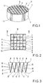
- FIGS. 1 to 6 shown therein is a first embodiment of the invention.
- a filter element F is mainly constituted of a filter medium 1, and a cylindrical side wall 3 surrounding the filter medium 1.
- the filter medium 1 and the side wall 3 are integrally formed of a porous and rigid sintered material produced by sintering synthetic resin powder.
- the filter element F additionally includes a frame (not shown) mounted on the side wall 3.
- the filter element F is incorporated into an air cleaner (not shown) of an automobile through the frame so as to filtrate or purifies air to be introduced into an internal combustion engine.
- the filter medium 1 has a square-based honeycombed structure with an upper or inlet side surface 12 and a lower or outlet side surface 13 parallel to the inlet side surface 12.
- the filter medium 1 is constituted of a plurality of basic filter units 2 each having a specific geometric configuration.
- each basic filter unit 2 is a bag-like member constituted of four filtration walls 7, and has a square inlet port 4 opening to the inlet side surface 12 and a closed linear end 8 terminating in the outlet side surface 13.
- the basic filter unit 2 includes an opened square edge 5 having four vertexes 5a, 5b, 5c and 5d, a closed linear edge 6 having two end points 11a and 11b and a midpoint 11c, a pair of vertical edges 9a one of which interconnects the vertex 5a and the end point 11a and the other of which interconnects the vertex 5c and the end point 11b, and a pair of inclined vertical edges 9b one of which interconnects the vertex 5b and the midpoint 11c and the other of which interconnects the vertex 5d and the midpoint 11c.
- the square edge 5 is coplanar with the inlet side surface 12 and defines the square inlet port 4.
- the linear edge 6 is contained in the outlet side surface 13 and defines the linear closed end 8.
- the vertical edges 9a and the inclined vertical edges 9b cooperate with the square edge 5 and the linear edge 6 to confine the four filtration walls 7.
- each filtration wall 7 is a three-dimensional skew wall having a linear cross-sectional configuration. Additionally, the width of the filtration wall 7 is reduced toward the linear edge 6.
- the inlet side surface 12 is divided by the square edges 5 into a square gridded pattern (FIG. 2).
- the outlet side surface 13 is also divided by the linear edges 6 into an enlarged square gridded pattern (FIG. 4).
- the gridded pattern of the outlet side surface 13 is inclined at 45 degrees relative to the gridded pattern of the inlet side surface 12 since each linear edge 6 corresponds to the diagonal line of the square edge 5.
- the linear edges 6 cooperate to define a plurality of square outlet ports 17 (FIGS. 3 and 4).
- the filter medium 1 includes a plurality of inlet channels 15 into which air to be filtrated is introduced through the inlet ports 4, and a plurality of outlet channels 16 from which air as filtrated is discharged to the outlet ports 17. Moreover, it is important to note that the filtration walls 7 of each basic filter unit 2 do not contact the filtration walls 7 of the adjacent basic filter unit 2 except for the square edge 5 and the vertical edges 9a.
- the filter medium 1 and the side wall 3 are integrally formed by utilizing an upper die 60 and a lower die 61 which has a molding space 62 therebetween. That is, the powdered synthetic resin, for example, polypropylene resin powder having particle diameter of from 100 to 800 micro meter, is filled in the molding space 62, and is then sintered at temperatures 10 to 50°C higher than the melting point of the resin, thereby forming the filter medium 1 and the side wall 3.
- the powdered synthetic resin for example, polypropylene resin powder having particle diameter of from 100 to 800 micro meter
- the sintered synthetic resin is a porous and air permeable material and has high rigidity due to bonding of the particles of the powder. Therefore, the filter medium 1 thus formed exhibit filtration function for purifying the air, and has flexural strength and self-sustainability which may resist filtration load applied thereto.
- the filter medium 1 has extremely high flexural strength than a conventional filter medium made of a filter paper. Thus, the filtration walls 7 of the basic filter unit 2 are prevented from contacting those of the adjacent basic filter unit 2. This may effectively prevent reduction of filtration performance of the filter medium 1.
- the side wall 3 exhibits also filtration function. This may lead to increased filtration capacity of the filter element F.
- the filter medium 1 may be cleaned by water-washing since the sintered synthetic resin exhibits excellent water-resistivity. This may lead to easy maintenance of the filter element F.
- the filter medium 1 is formed by molding of the powdered synthetic resin. This may eliminate the need for a folding process and a bonding process which are required in the conventional filter element, thereby contributing to reduction of the manufacturing cost of the filter element F.
- the filter element F may be miniaturized without decreasing available filtration area of the filter medium 1. This is because the filter medium 1 has the honeycombed structure and exhibits excellent flexural strength and self-sustainability.
- the basic filter units 2 are arranged in such a way that the linear edges 6 form the square gridded pattern on the outlet side surface 13, arrangement of the basic filter units 2 may be preferably modified, if required.
- FIG. 7 shown therein is a second embodiment of the present invention.
- This embodiment is a modification of the first embodiment. Therefore, only the construction which is different from that in the first embodiment will be explained. Further, elements which are the same as or similar to those in the first embodiment are given like reference numbers and their description will not be repeated.
- Each basic filter unit 2 is a bag-like member constituted of eight filtration walls 7, and has a square inlet port 4 opening to an inlet side surface 12 and a closed cross-shaped end 8 terminating in an outlet side surface 13.
- the basic filter unit 2 includes an opened square edge 5 having four vertexes 5a, 5b, 5c and 5d and four midpoints 5f, 5g, 5h and 5i, a closed cross-shaped edge 6 having four end points 18a, 18b, 18c and 18d and an intersection 18e, four vertical edges 19a which interconnect the midpoints 5f, 5g, 5h and 5i and the end points 18a, 18b, 18c and 18d, respectively, and four inclined vertical edges 19b which interconnect the vertex 5a, 5b, 5c and 5d and the intersection 18e, respectively.
- the square edge 5 is coplanar with the inlet side surface 12 and defines the square inlet port 4.
- the cross-shaped edge 6 is contained in the outlet side surface 13 and defines the cross-shaped closed end 8.
- the vertical edges 19a and the inclined vertical edges 19b cooperate with the square edge 5 and the cross-shaped edge 6 to confine the eight filtration walls 7.
- each filtration wall 7 is a three-dimensional skew wall having a linear cross-sectional configuration.
- FIG. 8 shown therein is a third embodiment of the present invention.
- This embodiment is a modification of the first embodiment. Therefore, only the construction which is different from that in the first embodiment will be explained. Further, elements which are the same as or similar to those in the first embodiment are given like reference numbers and their description will not be repeated.
- Each basic filter unit 2 is a bag-like member constituted of eight filtration walls 7, and has a square inlet port 4 opening to an inlet side surface 12 and a closed cross-shaped end 8 terminating in an outlet side surface 13.
- the basic filter unit 2 includes an opened square edge 5 having four vertexes 5a, 5b, 5c and 5d and four midpoints 5f, 5g, 5h and 5i, a closed cross-shaped edge 6 having four end points 22a, 22b, 22c and 22d and an intersection 22e, four vertical edges 24a which interconnect the vertexes 5a, 5b, 5c and 5d and the end points 22a, 22b, 22c and 22d, respectively, and four inclined vertical edges 24b which interconnect the midpoints 5f, 5g, 5h and 5i and the intersection 22e, respectively.
- the square edge 5 is coplanar with the inlet side surface 12 and defines the square inlet port 4.
- the cross-shaped edge 6 is contained in the outlet side surface 13 and defines the cross-shaped closed end 8.
- the vertical edges 24a and the inclined vertical edges 24b cooperate with the square edge 5 and the cross-shaped edge 6 to confine the eight filtration walls 7.
- each filtration wall 7 is a three-dimensional skew wall having a linear cross-sectional configuration.
- FIG. 9 shown therein is a fourth embodiment of the present invention.
- This embodiment is a modification of the first embodiment. Therefore, only the construction which is different from that in the first embodiment will be explained. Further, elements which are the same as or similar to those in the first embodiment are given like reference numbers and their description will not be repeated.
- Each basic filter unit 2 is a bag-like member constituted of a pair of filtration walls 7A and a pair of filtration walls 7B, and has a square inlet port 4 opening to an inlet side surface 12 and a linear closed end 8 terminating in an outlet side surface 13.
- the basic filter unit 2 includes a square edge 5 having four vertexes 5a, 5b, 5c and 5d, a linear edge 6 having two end points 27a and 27b, a pair of inclined vertical edges 28 which interconnect the vertexes 5a and 5d and the end point 27a, and a pair of inclined vertical edges 28' which interconnect the vertexes 5b and 5c and the end point 27b.
- the square edge 5 is coplanar with the inlet side surface 12 and defines the square inlet port 4.
- the linear edge 6 is contained in the outlet side surface 13 and defines the cross-shaped closed end 8.
- the adjacent inclined vertical edges 28 and 28' cooperate with the square edge 5 and the linear edge 6 to confine the filtration walls 7A.
- the adjacent inclined vertical edges 28 cooperate with the square edge 5 to confine one of the filtration walls 7B. Further, the adjacent inclined vertical edges 28' cooperate with the square edge 5 to confine the other of the filtration walls 7B.
- each filtration wall 7A is an inclined two-dimensional flat wall having a rectangular configuration.
- each filtration wall 7B is a two-dimensional flat wall having a triangular configuration and extending perpendicular to the outlet side surface 13.
- the outlet side surface 13 is divided by the linear edges 6 into a striped pattern (FIG. 9). Additionally, the linear edges 6 cooperate to define a plurality of elongated outlet ports (not shown). As will be appreciated, the both ends of each elongated outlet port are defined by the peripheral edge of the side wall 3.
- the filter medium 1 includes a plurality of inlet channels (not-shown) into which air to be filtrated is introduced through the inlet ports 4, and a plurality of gutter-like outlet channels (not shown) from which air as filtrated is discharged to the outlet ports.
- the filtration walls 7B of each basic filter unit 2 are common to the filtration walls 7B of the adjacent basic filter units 2.
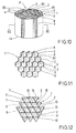
- FIGS. 10 to 14 shown therein is a fifth embodiment of the invention.
- This embodiment is a modification of the first embodiment. Therefore, only the construction which is different from that in the first embodiment will be explained. Further, elements which are the same as or similar to those in the first embodiment are given like reference numbers and their description will not be repeated.
- a filter element F is mainly constituted of a filter medium 1, and a side wall 3 surrounding the filter medium 1.
- the filter medium 1 and the side wall 3 are integrally formed of a porous and rigid sintered material produced by sintering of synthetic resin powder.
- the filter medium 1 has a hexagon-based honeycombed structure with an inlet side surface 12 and an outlet side surface 13 parallel to the inlet side surface 12.
- the filter medium 1 is constituted of a plurality of basic filter units 2 each having a specific geometric configuration.
- each basic filter unit 2 is a bag-like member constituted of six filtration walls 7, and has an opened regular hexagonal inlet port 4 opening to the inlet side surface 12 and a closed Y-shaped end 8 terminating in the outlet side surface 13.
- the basic filter unit 2 includes a regular hexagonal edge 30 having six vertexes 30a, 30b, 30c, 30d, 30e and 30f, a closed Y-shaped edge 6 having three end points 31a, 31b and 31c and a center 31d, three vertical edges 32a which interconnects the vertexes 30a, 30c and 30e and the end points 31a, 31b and 31c, respectively, and three inclined vertical edges 32b which interconnects the vertexes 30b, 30d and 30f and the center 31d.
- the regular hexagonal edge 30 is coplanar with the inlet side surface 12 and defines the square inlet port 4.
- the Y-shaped edge 6 is contained in the outlet side surface 13 and defines the Y-shaped closed end 8.
- the vertical edges 32a and the inclined vertical edges 32b cooperate with the regular hexagonal edge 30 and the Y-shaped edge 6 to confine the six filtration walls 7.
- each filtration wall 7 is a three-dimensional skew wall having a linear cross-sectional configuration.
- the inlet side surface 12 is divided by the regular hexagonal edges 30 into a regular hexagon-based honeycombed pattern (FIG. 11).
- the outlet side surface 13 is also divided by the Y-shaped edges 6 into a regular hexagon-based honeycombed pattern (FIG. 13).
- the pattern of the outlet side surface 13 is inclined at 60 degrees relative to the pattern of the inlet side surface 12.
- the Y-shaped edges 6 cooperate to define a plurality of regular hexagonal outlet ports 17 (FIG. 13).
- the filter medium 1 includes a plurality of inlet channels 15 into which air to be filtrated is introduced through the inlet ports 4, and a plurality of outlet channels 16 from which air as filtrated is discharged to the outlet ports 17. Moreover, it is important to note that the filtration walls 7 of each basic filter unit 2 do not contact the filtration walls 7 of the adjacent basic filter unit 2 except for the regular hexagonal edge 30 and the vertical edges 32a.
- FIG. 15 shown therein is a sixth embodiment of the present invention.
- This embodiment is a modification of the fifth embodiment. Therefore, only the construction which is different from that in the fifth embodiment will be explained. Further, elements which are the same as or similar to those in the fifth embodiment are given like reference numbers and their description will not be repeated.
- Each basic filter unit 2 is a bag-like member constituted of four filtration walls 7A, two filtration walls 7B, and has a regular hexagonal inlet port 4 opening to the inlet side surface 12 and a closed linear end 8 terminating in the outlet side surface 13.
- the basic filter unit 2 includes an opened regular hexagonal edge 30 having six vertexes 30a, 30b, 30c, 30d, 30e and 30f, a closed linear edge 6 having two end points 34a and 34b and a center 34c, two inclined vertical edges 35a and 35b which interconnects the vertexes 30a and 30b and the end points 34a, respectively, two inclined vertical edges 35c and 35d which interconnects the vertexes 30d and 30e and the end points 34b, respectively, and two inclined vertical edges 35e and 35f which interconnect the vertexes 30c and and 30f and the center 34c, respectively.
- the regular hexagonal edge 30 is coplanar with the inlet side surface 12 and defines the square inlet port 4.
- the linear edge 6 is contained in the outlet side surface 13 and defines the linear closed end 8.
- the inclined vertical edges 35a and 35b, and 35c and 35d cooperate with the regular hexagonal edge 30 to confine the two filtration walls 7B.
- the inclined vertical edges 35b and 35e, 35c and 35e, 35d and 35f, and 35a and 35f cooperate with the regular hexagonal edge 30 and the linear edge 6 to confine the four filtration walls 7A.
- each filtration wall 7A is a three-dimensional skew wall having a linear cross-sectional configuration.
- each filtration wall 7B is a two-dimensional flat wall having a triangular configuration and extending perpendicular to the outlet side surface 13.
- the outlet side surface 13 is divided by the linear edges 6 into a striped pattern (FIG. 15). Additionally, the linear edges 6 cooperate to define a plurality of elongated outlet ports (not shown). As will be appreciated, the both ends of each elongated outlet port are defined by the peripheral edge of the side wall 3.
- the filter medium 1 includes a plurality of inlet channels (not shown) into which air to be filtrated is introduced through the inlet ports 4, and a plurality of gutter-like outlet channels (not shown) from which air as filtrated is discharged to the outlet ports.
- the filtration walls 7A of each basic filter unit 2 are common to the filtration walls 7B of the adjacent basic filter units 2.
- FIGS. 16 and 17 shown therein is a seventh embodiment of the present invention.
- This embodiment is a modification of the fifth embodiment. Therefore, only the construction which is different from that in the fifth embodiment will be explained. Further, elements which are the same as or similar to those in the fifth embodiment are given like reference numbers and their description will not be repeated.
- Each basic filter unit 2 is a bag-like member constituted of two filtration walls 7A, four filtration walls 7B, and has a regular hexagonal inlet port 4 opening to the inlet side surface 12 and a linear closed end 8 terminating in the outlet side surface 13.
- the basic filter unit 2 includes a regular hexagonal edge 30 having six vertexes 30a, 30b, 30c, 30d, 30e and 30f, a linear edge 6 having two end points 37a and 37b, two vertical edges 38a and 38d which interconnect the vertexes 30a and 30d to the end points 37a and 37b, respectively, two inclined vertical edges 38b and 38f which interconnect the vertexes 30b and 30f to the end point 37a, and two inclined vertical edges 38c and 38e which interconnect the vertexes 30c and 30f to the end point 37b.
- the regular hexagonal edge 30 is coplanar with the inlet side surface 12 and defines the square inlet port 4.
- the linear edge 6 is contained in the outlet side surface 13 and defines the linear closed end 8.
- the vertical edge 38a cooperates with the inclined vertical edges 38b and 38f and the regular hexagonal edge 30 to confine the two filtration walls 7B.
- the vertical edge 38d cooperates with the inclined vertical edges 38c and 38e and the regular hexagonal edge 30 to confine the two filtration walls 7B.
- the inclined vertical edges 38b and 38c cooperate with the regular hexagonal edge 30 and the linear edge 6 to confine the filtration walls 7A.
- the inclined vertical edges 38e and 38f cooperate with the regular hexagonal edge 30 and the linear edge 6 to confine the filtration walls 7A.
- each filtration wall 7A is a two-dimensional flat wall having a trapezoidal configuration.
- each filtration wall 7B is a two-dimensional flat wall having a triangular configuration and extending perpendicular to the outlet side surface 13.
- the basic filter units 2 are arranged so that the outlet side surface 13 is divided by the linear edges 6 into a regular hexagonal gridded pattern.
- the filter medium 1 necessarily has a plurality of empty spaces. Therefore, the filter medium 1 includes a plurality of closure walls 36 to close the empty spaces.
- Each closure wall 36 is coplanar with the inlet side surface 12 and is formed with the same material as that of the filter medium 1.
- the linear edges 6 cooperate to define a plurality of regular hexagonal outlet ports 17.
- the filter medium 1 includes a plurality of inlet channels 15 into which air to be filtrated is introduced through the inlet ports 4, and a plurality of enlarged outlet channels 16 from which air as filtrated is discharged to the outlet ports.
- the filtration walls 7B of each basic filter unit 2 are common to the filtration walls 7B of the adjacent basic filter units 2.
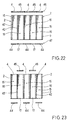
- FIGS. 18 to 23 shown therein is an eighth embodiment of the invention.
- This embodiment is a modification of the first embodiment. Therefore, only the construction which is different from that in the first embodiment will be explained. Further, elements which are the same as or similar to those in the first embodiment are given like reference numbers and their description will not be repeated.
- a filter element F is mainly constituted of a filter medium 1, and a side wall 3 enclosing the filter medium 1 and having a square configuration.
- the filter medium 1 and the side wall 3 are integrally formed of a porous and rigid sintered material produced by sintering synthetic resin powder.
- the filter medium 1 has a square-based honeycombed structure with an inlet side surface 12 and an outlet side surface 13 parallel to the inlet side surface 12.
- the filter medium 1 is essentially constituted of a plurality of basic filter units 2 each having a square cylindrical configuration.
- Each basic filter unit 2 has a square cylindrical configuration and is constituted of four side filtration walls 42 and a bottom filtration wall 44 coplanar with the outlet side surface 13.
- the basic filter units 2 are regularly arranged so that a plurality of square through bores are alternately formed between the basic filter units 2.
- the filter medium 1 includes a plurality of closure walls 45 to close the through bores.
- the closure walls 45 are formed of the same material as that of the filter medium 1.
- the closure walls 45 are integrally formed with the filter medium 1 and adapted to coplanar with the inlet side surface 12.
- the filter medium 1 has a plurality of square inlet ports 4 opening to the inlet side surface 12 and a plurality of square outlet ports 17 opening to the outlet side surface 13.
- the filter medium 1 includes a plurality of inlet channels 15 into which air to be filtrated is introduced through the inlet ports 4, and a plurality of enlarged outlet channels 16 from which air as filtrated is discharged to the outlet ports 17.
- the side wall 3 is partly common to the filtration walls 42 of the basic filter unit 2 arranged therealong.
- each basic filter unit 2 has a bottomless square cylindrical configuration and is constituted of four side filtration walls 42.
- the filter medium 1 additionally includes an inlet side plate 46 having a plurality of inlet ports 4 and a plurality of closure walls 45, and an outlet side plate 47 having a plurality of bottom filtration walls 44 and a plurality of outlet ports 17.
- the inlet side plate 46 and the outlet side plate 47 are combined to the filter medium 1 by bonding or welding.
- the filter medium 1 is formed with a plurality of inlet channels 15 into which air to be filtrated is introduced through the inlet ports 4, and a plurality of enlarged outlet channels 16 from which air as filtrated is discharged to the outlet ports 17.
- each basic filter unit 2 has a bottomless square cylindrical configuration and is constituted of four side filtration walls 42.
- the filter medium 1 additionally includes a plurality of closure walls 45, and a plurality of bottom filtration walls 44.
- the closure walls 45 and the bottom filtration walls 44 are combined to the filter medium 1 by bonding or welding.
- the filter medium 1 is formed with a plurality of inlet channels 15 into which air to be filtrated is introduced through the inlet ports 4, and a plurality of enlarged outlet channels 16 from which air as filtrated is discharged to the outlet ports 17.
- the filter medium 1 of eighth embodiment may be further modified.
- the basic filter units 2 may have triangular or rectangular cylindrical configuration.
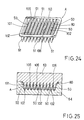
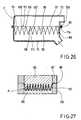
- FIGS. 24 to 26 shown therein is a ninth embodiment of the invention.
- a filter element A is constituted of a filter medium 101, and a rectangular frame 80 to which the filter medium 101 is integrally incorporated.
- the filter medium 101 and the frame 80 are integrally formed of a porous and rigid sintered material produced by sintering synthetic resin powder.
- the filter medium 101 has an inlet side surface 112 and an outlet side surface 113, and is constituted of a plurality of basic filter units 102 which are integrally connected at connecting edges 106 to form a corrugated structure.
- Each basic filter unit 102 is constituted of a wedge-shaped filtration wall 50 and a pair of end walls or side walls 51.
- the filter medium 101 thus constructed has a plurality of inlet channels 115 facing the inlet side surface 112 and a plurality of outlet channels 116 facing the outlet side surface 113.
- the filter medium 101 and the frame 80 are integrally formed by utilizing an upper die 63 and a lower die 64. That is, the powdered synthetic resin, for example, polypropylene resin powder is filled in a molding space between the upper die 63 and the lower die 64, and then sintered at a suitable temperature, thereby forming the filter element A.
- the powdered synthetic resin for example, polypropylene resin powder
- the filter element A thus formed is incorporated into an air cleaner C having an upper casing 70 and a lower casing 71, in which the frame 80 of the filter element A is received between a peripheral edge 70a of the upper casing 70 and a peripheral edge 71a of the lower casing 71. Then, the frame 80 is bonded to the peripheral edges 70a and 71a by welding or the like, thereby fixing the filter element A to the air cleaner C. It is preferable that the casings 70 and 71 are formed of synthetic resin having properties identical with those of the synthetic resin for the filter element A.
- the frame 80 exhibits filtration function. This may lead to increased filtration capacity of the filter element A.
- the filter medium 101 is integrally formed with the frame 80. This may eliminate the need for a folding process of the filter medium 101 and a connecting process of the filter medium 101 to the frame 80, thereby reducing the manufacturing cost of the filter element A.
- the filter element A is assembled by welding the frame 80 to the peripheral edges 70a and 71a of the casings 70 and 71. This may eliminate the need for a sealing mechanism between the filter element A and the casings 70 and 71 of the air cleaner C.
- both of the filter medium 101 and the frame 80 are made of the sintered synthetic resin. This may facilitate reuse of the filter element A.
- the filter element A may be miniaturized without decreasing available filtration area of the filter medium 101. This is because the filter medium 101 exhibits excellent flexural strength and self-sustainability.
- FIG. 27 shown therein is a tenth embodiment of the present invention.
- This embodiment is a modification of the ninth embodiment. Therefore, only the construction which is different from that in the ninth embodiment will be explained. Further, elements which are the same as or similar to those in the ninth embodiment are given like reference numbers and their description will not be repeated.
- a filter element A is constituted of a filter medium 101, and a rectangular frame 80.
- the filter medium 101 is formed of synthetic resin powder.
- the frame 80 is formed of synthetic resin powder which is different from the synthetic resin powder for the filter medium 101.
- the synthetic resin powder for the frame 80 has softness and elasticity greater than those of the synthetic resin powder for the filter medium 101, and exhibits high affinity for the synthetic resin powder for the filter medium 101.
- the filter medium 101 and the frame 80 are integrally formed by utilizing an upper die 65 and a lower die 66 for forming the filter medium 101 and an upper die 67 and a lower die 68 for forming the frame 80. That is, the powdered synthetic resin for the filter medium 101 is filled in a molding space between the upper die 65 and the lower die 66, and the powdered synthetic resin for the frame 80 is filled in a molding space between the upper die 67 and the lower die 68. Then, the both of the powdered synthetic resins are sintered, thereby forming the filter element A.
- the dies 65 and 66 are heated to a temperature suitable for sintering the powdered synthetic resin for the filter medium 101, and the dies 67 and 68 are heated to a temperature suitable for sintering the powdered synthetic resin for the frame 80.
- the filter element A thus formed is incorporated into an air cleaner (not shown) having an upper casing and a lower casing, in which the frame 80 is closely received between a peripheral edge of the upper casing and a peripheral edge of the lower casing. Then, the frame 80 is fixed between the peripheral edges of the upper and lower casings by clamping or the like, thereby mounting the filter element A to the air cleaner.
- the frame 80 of the filter element A is formed of the highly elastic material. This may eliminate the need for a sealing mechanism between the filter element A and the casings of the air cleaner.
- the filter medium 101 is made of the sintered synthetic resin
- the frame 80 is made of the sintered synthetic resin similar to that for the filter medium 101. This may facilitate reuse of the filter element A.
Landscapes
- Chemical & Material Sciences (AREA)
- Physics & Mathematics (AREA)
- Geometry (AREA)
- Chemical Kinetics & Catalysis (AREA)
- Engineering & Computer Science (AREA)
- Combustion & Propulsion (AREA)
- Mechanical Engineering (AREA)
- General Engineering & Computer Science (AREA)
- Filtering Of Dispersed Particles In Gases (AREA)
- Filtering Materials (AREA)
Description
Claims (8)
- A filter element for an air cleaner, comprising
a filter medium (1) having a plurality of basic filter units (2), said filter medium being integrally formed of a porous sintered material produced by sintering powdered synthetic resin,
characterized in thatsaid basic filter units (2) are arranged in a honeycomb structure,each of said basic filter units (2) is a bag-like member that comprises a plurality of filtration walls (7, 7A, 7B) and has a polygonal opening edge (4) and a closed edge (8) opposed to said polygonal opening edge, andeach of said basic filter units (2) has a plurality of vertical edges (9a, b; 19a,b; 24a,b; 28,28'; 32a,b; 35a,b; 38a-f) each of which interconnects a point on said opening edge and a point on said closed edge, said vertical edges being defined by said filtration walls. - The filter element as defined in claim 1, wherein
some of said vertical edges of said basic filter units are joined with each other. - The filter element as defined in claim 1 or 2, said wherein
said closed edges of said basic filter units are connected with each other. - The filter element as defined in one of claims 1 to 3, wherein
all or some of said filtration walls comprise plane walls (7). - The filter element as defined in one of claims 1 to 4, wherein
all or some of said filtration walls comprise skew walls (7). - The filter element as defined in one of claims 1 to 5, further comprising
a cylindrical side wall (3) surrounding said filter medium, said cylindrical side wall being integral with said filter medium. - A filter element for an air cleaner, comprisinga filter medium (1) having a plurality of basic filter units (2), anda frame (80) surrounding said filter medium,said filter medium being integrally formed of a porous sintered material produced by sintering powdered synthetic resin and having a corrugated structure, characterized in thateach of said basic filter units is a gutter-like member consisting of a wedge-shaped filtration wall and a pair of sidewalls, andsaid frame is integral with said filter medium.
- The filter element as defined in claim 7, wherein
said frame is formed of powdered synthetic resin different from the powdered synthetic resin for said filter medium, said powdered synthetic resin for said frame having softness and elasticity greater than those of the powdered synthetic resin for said filter medium.
Applications Claiming Priority (3)
| Application Number | Priority Date | Filing Date | Title |
|---|---|---|---|
| JP3938/96 | 1996-01-12 | ||
| JP8003938A JPH09187614A (en) | 1996-01-12 | 1996-01-12 | Filter element |
| JP393896 | 1996-01-12 |
Publications (2)
| Publication Number | Publication Date |
|---|---|
| EP0783914A1 EP0783914A1 (en) | 1997-07-16 |
| EP0783914B1 true EP0783914B1 (en) | 2001-11-21 |
Family
ID=11571079
Family Applications (1)
| Application Number | Title | Priority Date | Filing Date |
|---|---|---|---|
| EP97100194A Expired - Lifetime EP0783914B1 (en) | 1996-01-12 | 1997-01-08 | Filter element for air cleaner |
Country Status (5)
| Country | Link |
|---|---|
| US (1) | US5851250A (en) |
| EP (1) | EP0783914B1 (en) |
| JP (1) | JPH09187614A (en) |
| AU (1) | AU709175B2 (en) |
| DE (1) | DE69708344T2 (en) |
Cited By (2)
| Publication number | Priority date | Publication date | Assignee | Title |
|---|---|---|---|---|
| US9108394B2 (en) | 2008-08-06 | 2015-08-18 | Donaldson Company, Inc. | Method of making a Z-media having flute closures |
| US9517430B2 (en) | 2007-02-02 | 2016-12-13 | Donaldson Company, Inc. | Air filtration media pack, filter element, air filtration media, and methods |
Families Citing this family (18)
| Publication number | Priority date | Publication date | Assignee | Title |
|---|---|---|---|---|
| US6033452A (en) * | 1998-03-25 | 2000-03-07 | Xerox Corporation | Xerographic customer replaceable unit filter and assembly method |
| DE19832509A1 (en) * | 1998-07-20 | 2000-01-27 | Behr Gmbh & Co | Filter with large adsorption capacity, e.g. for vehicle heating or air-conditioning systems, comprises adsorber particles which are joined together to form a self supporting microporous filter material |
| WO2000004985A1 (en) * | 1998-07-22 | 2000-02-03 | Koch Membrane Systems, Inc. | Multi-lumen porous membrane and method of construction |
| US6238561B1 (en) | 1999-09-24 | 2001-05-29 | Nelson Industries, Inc. | Corrugated axial filter with simple fold pattern and method of making it |
| JP2002186809A (en) * | 2000-12-20 | 2002-07-02 | Toyoda Spinning & Weaving Co Ltd | Filter and method for manufacturing the same |
| DE50202491D1 (en) * | 2001-06-18 | 2005-04-21 | Hjs Fahrzeugtechnik Gmbh & Co | PARTICULATE FILTER FOR EXHAUST GASES FROM INTERNAL COMBUSTION ENGINES |
| EP1399239B1 (en) * | 2001-06-18 | 2005-03-16 | HJS Fahrzeugtechnik GmbH & Co. | Particle filter operating by means of soot combustion and used for diesel engines |
| JP3719232B2 (en) * | 2002-06-18 | 2005-11-24 | トヨタ自動車株式会社 | Particulate filter for internal combustion engine |
| RU2281144C1 (en) * | 2005-01-11 | 2006-08-10 | ЗАО "Кондор-Эко" | Filter |
| US7611559B2 (en) * | 2006-02-07 | 2009-11-03 | Mann & Hummel Gmbh | Filter element |
| WO2008106587A1 (en) * | 2007-02-28 | 2008-09-04 | Stoneridge, Inc. | Filtration device for use with a fuel vapor recovery system |
| EP2829310A1 (en) | 2007-06-26 | 2015-01-28 | Donaldson Company, Inc. | Filtration media pack |
| JP5986354B2 (en) | 2008-02-04 | 2016-09-06 | ドナルドソン カンパニー,インコーポレイティド | Method and apparatus for forming filtration media with flutes |
| CN102159296A (en) | 2008-07-25 | 2011-08-17 | 唐纳森公司 | Air filtration media packaging, filter element, air filtration media, and method |
| WO2011017352A2 (en) | 2009-08-03 | 2011-02-10 | Donaldson Company, Inc. | Method and apparatus for forming fluted filtration media having tapered flutes |
| MX2012008542A (en) | 2010-01-25 | 2012-11-12 | Donaldson Co Inc | Pleated filtration media having tapered flutes. |
| DE112017002360T5 (en) * | 2016-07-13 | 2019-02-14 | Cummins Filtration Ip, Inc. | Filter element with conical circumference |
| CN108180592B (en) * | 2017-12-27 | 2020-04-24 | 昆山斯莱姆节能科技有限公司 | Through-wall purification ventilation pipe with induced draft fan |
Family Cites Families (19)
| Publication number | Priority date | Publication date | Assignee | Title |
|---|---|---|---|---|
| US3048537A (en) * | 1958-01-06 | 1962-08-07 | Pall Corp | Porous articles of polyethylene polymers and process of making the same |
| US3358427A (en) * | 1965-10-19 | 1967-12-19 | Msa Res Corp | Filter containing tubular filter cells |
| US3410062A (en) * | 1966-09-12 | 1968-11-12 | Cambridge Filter Corp | Filter |
| GB1241858A (en) * | 1968-12-30 | 1971-08-04 | Ici Ltd | Sorption of nitrogen dioxide by polyamides |
| DE2541331B2 (en) * | 1975-09-17 | 1978-08-31 | Fa. Carl Freudenberg, 6940 Weinheim | Gas filter element |
| CH608976A5 (en) * | 1976-06-04 | 1979-02-15 | Luwa Ag | |
| JPS56110736A (en) * | 1980-02-08 | 1981-09-02 | Asahi Chem Ind Co Ltd | Porous sintered product from acrylonitrile |
| DE3024324A1 (en) * | 1980-06-27 | 1982-01-21 | Herding GmbH Entstaubungsanlagen, 8450 Amberg | Gas filter, esp. air filter, has two coaxial porous layers - the outer finer the inner coarser, esp. of sintered polyethylene |
| GB2109268B (en) * | 1981-11-16 | 1984-10-03 | Process Scient Innovations | Gas purifiers |
| DE3413213A1 (en) * | 1984-04-07 | 1985-10-24 | Herding GmbH Entstaubungsanlagen, 8450 Amberg | Filter element for separating out solid particles from gaseous or liquid media |
| US4925561A (en) * | 1988-03-31 | 1990-05-15 | Tsuchiya Mfg. Co., Ltd. | Composite planar and triangularly pleated filter element |
| JP2547251B2 (en) * | 1989-04-20 | 1996-10-23 | 日鉄鉱業株式会社 | Method for manufacturing filter element used in dust collector |
| US4976857A (en) * | 1989-05-03 | 1990-12-11 | Newport Filters, Inc. | Filter element and fabrication methodology |
| JP3223194B2 (en) * | 1991-07-18 | 2001-10-29 | 本田技研工業株式会社 | Sliding member |
| JPH0743980Y2 (en) | 1991-09-13 | 1995-10-09 | 国際電気株式会社 | Coaxial connector |
| DE4211529A1 (en) * | 1992-04-06 | 1993-10-07 | Herding Entstaubung | Filter element with a dimensionally stable, permeable-porous plastic molded body |
| DE4220624A1 (en) * | 1992-06-24 | 1994-01-05 | Zahnradfabrik Friedrichshafen | Rotary slide valve, especially for power steering |
| DK98993D0 (en) * | 1993-09-01 | 1993-09-01 | Per Stobbe | DUST FILTER FOR HOT GASES |
| JP3668283B2 (en) * | 1995-05-16 | 2005-07-06 | 三菱樹脂株式会社 | Porous multilayer plastic filter and manufacturing method thereof |
-
1996
- 1996-01-12 JP JP8003938A patent/JPH09187614A/en active Pending
- 1996-12-31 AU AU76550/96A patent/AU709175B2/en not_active Ceased
-
1997
- 1997-01-02 US US08/778,030 patent/US5851250A/en not_active Expired - Fee Related
- 1997-01-08 DE DE69708344T patent/DE69708344T2/en not_active Expired - Fee Related
- 1997-01-08 EP EP97100194A patent/EP0783914B1/en not_active Expired - Lifetime
Cited By (2)
| Publication number | Priority date | Publication date | Assignee | Title |
|---|---|---|---|---|
| US9517430B2 (en) | 2007-02-02 | 2016-12-13 | Donaldson Company, Inc. | Air filtration media pack, filter element, air filtration media, and methods |
| US9108394B2 (en) | 2008-08-06 | 2015-08-18 | Donaldson Company, Inc. | Method of making a Z-media having flute closures |
Also Published As
| Publication number | Publication date |
|---|---|
| EP0783914A1 (en) | 1997-07-16 |
| DE69708344D1 (en) | 2002-01-03 |
| US5851250A (en) | 1998-12-22 |
| AU709175B2 (en) | 1999-08-26 |
| DE69708344T2 (en) | 2002-07-25 |
| AU7655096A (en) | 1997-07-17 |
| JPH09187614A (en) | 1997-07-22 |
Similar Documents
| Publication | Publication Date | Title |
|---|---|---|
| AU709175B2 (en) | Filter element for air cleaner | |
| EP0713421B1 (en) | Filter for the filtration of a fluid flow | |
| KR100913629B1 (en) | Front inlet filter element | |
| EP1174170B1 (en) | Filter | |
| US5509950A (en) | Filter device for the filtration of gases and/or fluids | |
| US5290447A (en) | Block-shaped pleated filter insert | |
| US5679122A (en) | Filter for the filtration of a fluid flow | |
| US5810898A (en) | Nestable pleated filter | |
| EP0649335B1 (en) | Filter device for the filtration of fluids | |
| EP1086736B1 (en) | Corrugated axial filter with simple fold pattern | |
| JP2005505412A (en) | Interconnect filter frame and framework method | |
| EP3197583B1 (en) | V-type filter frame | |
| JPS5938005B2 (en) | Transmission fluid filter | |
| JP4675545B2 (en) | Filter module | |
| WO1994022557A1 (en) | Filter device for the filtration of fluids | |
| US20050061729A1 (en) | Filter module and process for the production of a filled filter module | |
| JP2025532354A (en) | Filter element and filter device | |
| JPH0747093B2 (en) | Filter member | |
| JP4393732B2 (en) | Fluid filter | |
| JP2502088Y2 (en) | Fluid filter device for automatic transmission | |
| JP3569770B2 (en) | Filter media and unit filters | |
| JP7785556B2 (en) | Filter Device | |
| JPH0538805Y2 (en) | ||
| CN222427404U (en) | Folding filter medium, filter element, filter device and transport means | |
| JPH11165014A (en) | Filter element |
Legal Events
| Date | Code | Title | Description |
|---|---|---|---|
| PUAI | Public reference made under article 153(3) epc to a published international application that has entered the european phase |
Free format text: ORIGINAL CODE: 0009012 |
|
| AK | Designated contracting states |
Kind code of ref document: A1 Designated state(s): DE FR GB IT |
|
| 17P | Request for examination filed |
Effective date: 19971103 |
|
| 17Q | First examination report despatched |
Effective date: 19991001 |
|
| GRAG | Despatch of communication of intention to grant |
Free format text: ORIGINAL CODE: EPIDOS AGRA |
|
| RIC1 | Information provided on ipc code assigned before grant |
Free format text: 7B 01D 39/16 A, 7F 02M 35/024 B, 7B 01D 46/24 B |
|
| GRAG | Despatch of communication of intention to grant |
Free format text: ORIGINAL CODE: EPIDOS AGRA |
|
| GRAH | Despatch of communication of intention to grant a patent |
Free format text: ORIGINAL CODE: EPIDOS IGRA |
|
| GRAH | Despatch of communication of intention to grant a patent |
Free format text: ORIGINAL CODE: EPIDOS IGRA |
|
| GRAA | (expected) grant |
Free format text: ORIGINAL CODE: 0009210 |
|
| AK | Designated contracting states |
Kind code of ref document: B1 Designated state(s): DE FR GB IT |
|
| PGFP | Annual fee paid to national office [announced via postgrant information from national office to epo] |
Ref country code: GB Payment date: 20011218 Year of fee payment: 6 |
|
| PGFP | Annual fee paid to national office [announced via postgrant information from national office to epo] |
Ref country code: FR Payment date: 20011227 Year of fee payment: 6 |
|
| REG | Reference to a national code |
Ref country code: GB Ref legal event code: IF02 |
|
| REF | Corresponds to: |
Ref document number: 69708344 Country of ref document: DE Date of ref document: 20020103 |
|
| PGFP | Annual fee paid to national office [announced via postgrant information from national office to epo] |
Ref country code: DE Payment date: 20020130 Year of fee payment: 6 |
|
| ET | Fr: translation filed | ||
| PLBE | No opposition filed within time limit |
Free format text: ORIGINAL CODE: 0009261 |
|
| STAA | Information on the status of an ep patent application or granted ep patent |
Free format text: STATUS: NO OPPOSITION FILED WITHIN TIME LIMIT |
|
| 26N | No opposition filed | ||
| PG25 | Lapsed in a contracting state [announced via postgrant information from national office to epo] |
Ref country code: GB Free format text: LAPSE BECAUSE OF NON-PAYMENT OF DUE FEES Effective date: 20030108 |
|
| PG25 | Lapsed in a contracting state [announced via postgrant information from national office to epo] |
Ref country code: DE Free format text: LAPSE BECAUSE OF NON-PAYMENT OF DUE FEES Effective date: 20030801 |
|
| GBPC | Gb: european patent ceased through non-payment of renewal fee |
Effective date: 20030108 |
|
| PG25 | Lapsed in a contracting state [announced via postgrant information from national office to epo] |
Ref country code: FR Free format text: LAPSE BECAUSE OF NON-PAYMENT OF DUE FEES Effective date: 20030930 |
|
| REG | Reference to a national code |
Ref country code: FR Ref legal event code: ST |
|
| PG25 | Lapsed in a contracting state [announced via postgrant information from national office to epo] |
Ref country code: IT Free format text: LAPSE BECAUSE OF NON-PAYMENT OF DUE FEES Effective date: 20050108 |