EP0782204A1 - Vent cap for a lithium battery - Google Patents
Vent cap for a lithium battery Download PDFInfo
- Publication number
- EP0782204A1 EP0782204A1 EP96112177A EP96112177A EP0782204A1 EP 0782204 A1 EP0782204 A1 EP 0782204A1 EP 96112177 A EP96112177 A EP 96112177A EP 96112177 A EP96112177 A EP 96112177A EP 0782204 A1 EP0782204 A1 EP 0782204A1
- Authority
- EP
- European Patent Office
- Prior art keywords
- depression
- vent cap
- vent
- battery
- lithium
- Prior art date
- Legal status (The legal status is an assumption and is not a legal conclusion. Google has not performed a legal analysis and makes no representation as to the accuracy of the status listed.)
- Granted
Links
- WHXSMMKQMYFTQS-UHFFFAOYSA-N Lithium Chemical compound [Li] WHXSMMKQMYFTQS-UHFFFAOYSA-N 0.000 title claims abstract description 21
- 229910052744 lithium Inorganic materials 0.000 title claims abstract description 21
- 229910000733 Li alloy Inorganic materials 0.000 claims abstract description 5
- 239000001989 lithium alloy Substances 0.000 claims abstract description 5
- 239000003792 electrolyte Substances 0.000 claims abstract description 4
- 150000003839 salts Chemical class 0.000 claims abstract description 4
- 230000000903 blocking effect Effects 0.000 claims description 18
- 230000002093 peripheral effect Effects 0.000 claims description 7
- 230000009172 bursting Effects 0.000 description 7
- 238000004880 explosion Methods 0.000 description 6
- 238000007599 discharging Methods 0.000 description 5
- 229910052751 metal Inorganic materials 0.000 description 3
- 239000002184 metal Substances 0.000 description 3
- 229910052782 aluminium Inorganic materials 0.000 description 1
- XAGFODPZIPBFFR-UHFFFAOYSA-N aluminium Chemical compound [Al] XAGFODPZIPBFFR-UHFFFAOYSA-N 0.000 description 1
- 238000011161 development Methods 0.000 description 1
- 230000018109 developmental process Effects 0.000 description 1
- 239000006185 dispersion Substances 0.000 description 1
- 239000012535 impurity Substances 0.000 description 1
- 238000009413 insulation Methods 0.000 description 1
- 239000012212 insulator Substances 0.000 description 1
- 238000012856 packing Methods 0.000 description 1
- 230000009257 reactivity Effects 0.000 description 1
- 230000000630 rising effect Effects 0.000 description 1
Images


Classifications
-
- H—ELECTRICITY
- H01—ELECTRIC ELEMENTS
- H01M—PROCESSES OR MEANS, e.g. BATTERIES, FOR THE DIRECT CONVERSION OF CHEMICAL ENERGY INTO ELECTRICAL ENERGY
- H01M50/00—Constructional details or processes of manufacture of the non-active parts of electrochemical cells other than fuel cells, e.g. hybrid cells
- H01M50/30—Arrangements for facilitating escape of gases
- H01M50/342—Non-re-sealable arrangements
- H01M50/3425—Non-re-sealable arrangements in the form of rupturable membranes or weakened parts, e.g. pierced with the aid of a sharp member
-
- H—ELECTRICITY
- H01—ELECTRIC ELEMENTS
- H01M—PROCESSES OR MEANS, e.g. BATTERIES, FOR THE DIRECT CONVERSION OF CHEMICAL ENERGY INTO ELECTRICAL ENERGY
- H01M10/00—Secondary cells; Manufacture thereof
- H01M10/05—Accumulators with non-aqueous electrolyte
- H01M10/052—Li-accumulators
-
- H—ELECTRICITY
- H01—ELECTRIC ELEMENTS
- H01M—PROCESSES OR MEANS, e.g. BATTERIES, FOR THE DIRECT CONVERSION OF CHEMICAL ENERGY INTO ELECTRICAL ENERGY
- H01M50/00—Constructional details or processes of manufacture of the non-active parts of electrochemical cells other than fuel cells, e.g. hybrid cells
- H01M50/10—Primary casings; Jackets or wrappings
- H01M50/147—Lids or covers
- H01M50/148—Lids or covers characterised by their shape
- H01M50/152—Lids or covers characterised by their shape for cells having curved cross-section, e.g. round or elliptic
-
- H—ELECTRICITY
- H01—ELECTRIC ELEMENTS
- H01M—PROCESSES OR MEANS, e.g. BATTERIES, FOR THE DIRECT CONVERSION OF CHEMICAL ENERGY INTO ELECTRICAL ENERGY
- H01M50/00—Constructional details or processes of manufacture of the non-active parts of electrochemical cells other than fuel cells, e.g. hybrid cells
- H01M50/30—Arrangements for facilitating escape of gases
- H01M50/383—Flame arresting or ignition-preventing means
-
- H—ELECTRICITY
- H01—ELECTRIC ELEMENTS
- H01M—PROCESSES OR MEANS, e.g. BATTERIES, FOR THE DIRECT CONVERSION OF CHEMICAL ENERGY INTO ELECTRICAL ENERGY
- H01M6/00—Primary cells; Manufacture thereof
- H01M6/14—Cells with non-aqueous electrolyte
-
- H—ELECTRICITY
- H01—ELECTRIC ELEMENTS
- H01M—PROCESSES OR MEANS, e.g. BATTERIES, FOR THE DIRECT CONVERSION OF CHEMICAL ENERGY INTO ELECTRICAL ENERGY
- H01M6/00—Primary cells; Manufacture thereof
- H01M6/14—Cells with non-aqueous electrolyte
- H01M6/16—Cells with non-aqueous electrolyte with organic electrolyte
-
- Y—GENERAL TAGGING OF NEW TECHNOLOGICAL DEVELOPMENTS; GENERAL TAGGING OF CROSS-SECTIONAL TECHNOLOGIES SPANNING OVER SEVERAL SECTIONS OF THE IPC; TECHNICAL SUBJECTS COVERED BY FORMER USPC CROSS-REFERENCE ART COLLECTIONS [XRACs] AND DIGESTS
- Y02—TECHNOLOGIES OR APPLICATIONS FOR MITIGATION OR ADAPTATION AGAINST CLIMATE CHANGE
- Y02E—REDUCTION OF GREENHOUSE GAS [GHG] EMISSIONS, RELATED TO ENERGY GENERATION, TRANSMISSION OR DISTRIBUTION
- Y02E60/00—Enabling technologies; Technologies with a potential or indirect contribution to GHG emissions mitigation
- Y02E60/10—Energy storage using batteries
Definitions
- a lithium battery which includes an electrolyte which is in electrical contact with an anode of lithium or lithium alloy and a cathode containing at least one metallic salt has been developed and widely utilized in various electronic devices.
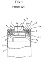
- FIG. 1 illustrates a partly sectional view of the upper structure of a conventional coiled lithium battery.
- reference numeral 1 denotes a cylindrical casing with a bottom (not shown), into which a coiled electrode body 2 is installed.
- Casing 1 has, at its upper portion, a narrow portion as indicated by 1a.
- Vent cap 3 is shaped in a hat shape and is formed of a circular flat portion 3a and a projected portion 3b projected from the central portion of flat portion 3a upwardly and disposed coaxially with flat portion 3a.
- a depression 22 which is formed of two inclined planes and a horizontal plane connecting two inclined planes with each other, is provided at the top side of projected portion 14 by press forming. Two sides of depression 22 are cut on press forming, so that two trapezoid vent holes 24 are formed face to face with each other.
- depression 22 is shaped in a rectangular plane shape and a trapezoid vertical-sectional shape.
- blocking plate 25 If blocking plate 25 is further installed, the above blocking effect becomes higher. Gas and flame generated with the battery first make contact with blocking plate 25 to reduce their bursting pressure and then burst out through grooves 25a of blocking plate 25.
Landscapes
- Chemical & Material Sciences (AREA)
- Chemical Kinetics & Catalysis (AREA)
- Electrochemistry (AREA)
- General Chemical & Material Sciences (AREA)
- Engineering & Computer Science (AREA)
- Manufacturing & Machinery (AREA)
- Gas Exhaust Devices For Batteries (AREA)
- Secondary Cells (AREA)
Abstract
Description
- The present invention relates to a vent cap for a lithium battery, and more particularly to a vent cap for a lithium battery constructed to reduce the bursting distance of gas and flame generated in the battery when the battery burns or explodes.
- Recently, a lithium battery which includes an electrolyte which is in electrical contact with an anode of lithium or lithium alloy and a cathode containing at least one metallic salt has been developed and widely utilized in various electronic devices.
- However, because metal lithium has high reactivity, the temperature and pressure of the battery are apt to rise by moisture or active impurities contained in the battery.
- Moreover, according to recent developments, there are increasing cases of wrong use of the battery of this kind such that the battery, despite the fact that the battery is a primary battery, is erroneously subjected to charging or forced discharging by an external power source. An example of forced discharging, which occurs many times, is that one or more old batteries, which are already used and the discharging capacity thereof is depleted or small, are connected with one or more new batteries of which the discharging capacity is plentiful. In this case, if the battery of which the discharging capacity is depleted is forced to be discharged, the battery is loaded with a minus voltage by the current supplied from the other healthy battery.
- If such error occurs in a lithium battery, the battery is apt to generate heat due to an internal short circuit and there are some cases of explosion of the battery.
- Besides, when the lithium batteries are subjected to work using relatively high current, the batteries generate a lot of heat and the temperature of the battery becomes higher at the central portion, and an insulation layer between positive and negative electrode plates is molten, whereby an internal short circuit occurs and a further high current flows there with the generation of further heat. Accordingly, the lithium and lithium alloy become molten and the battery burns or explodes.
- In order to prevent such burning or explosion of the battery, an explosion resistant structure has been utilized for safety.
- FIG. 1 illustrates a partly sectional view of the upper structure of a conventional coiled lithium battery. With reference to FIG. 1, reference numeral 1 denotes a cylindrical casing with a bottom (not shown), into which a
coiled electrode body 2 is installed. Casing 1 has, at its upper portion, a narrow portion as indicated by 1a.Vent cap 3 is shaped in a hat shape and is formed of a circular flat portion 3a and a projectedportion 3b projected from the central portion of flat portion 3a upwardly and disposed coaxially with flat portion 3a. Projectedportion 3b is shaped in a cylindrical shape and has afirst vent hole 3c formed at the central portion of the top wall of projectedportion 3b and asecond vent hole 3d formed at the side wall of projectedportion 3b. The peripheral edge portion of flat portion 3a ofvent cap 3 is clamped between narrow portion 1a and a foldedupper edge portion 1b of casing 1 to expose projectedportion 3b. - A positive temperature coefficient (hereinafter simply referred to as "PTC")
element 4 is made of metal which has its electric resistance proportional to the temperature. When the inner temperature of the battery is over a predetermined value,PTC element 4 has very high resistance and serves as an insulator for opening the inner electric circuit of the battery.PTC element 4 has a round disk shape opened by a hole 4a at its central portion. Within the battery,PTC element 4 is laid belowvent cap 3.PTC element 4, aring plate 5, aburst disk 6 and alower cap 7 are installed within casing 1 in this order.Ring plate 5 serves for shock-absorbing and is made of plastic in a round disk shape with its central portion opened by ahole 5a.Burst disk 6 is made of metal plate, such as aluminum plate, in a round disk shape in order to break over a predetermined value of inner pressure of the battery.Lower cap 7 has a projected portion 7a which is projected toward the bottom of casing 1. Projected portion 7a has ahole 7b at its central portion. Outer peripheral edges ofring plate 5 andburst disk 6 are clamped by a folded outer peripheral edge oflower cap 7. Ventcap 3,PTC element 4 andlower cap 7 includingring plate 5 andburst disk 6 are installed in this order and are clamped between narrow portion 1a of casing 1 and a radially inwardly foldedupper edge portion 1b of casing 1 through a ring-shaped packing 9. - When the inner pressure of the battery constructed as described above rises, burst
disk 6 expands upwardly. When burstdisk 6 further expands, it will break to exhaust the inner gas of the battery outward through first andsecond vent holes - However, in the conventional battery structure, most of gas and flame generated are exhausted through
first vent hole 3c which is located just aboveholes vent cap 3. Accordingly, gas and flame generated from the battery burst out substantially without dispersion to attain a long distance, thereby damaging electronic devices including the battery and possibly injuring a person. - The present invention is devised to solve the foregoing problems. An object of the present invention is to provide a vent cap for a lithium battery constructed to disperse gas and flame generated during an explosion so as to reduce their bursting pressure and distance.
- In order to accomplish the above object of the present invention, there is provided a vent cap for a lithium battery comprising:
- a circular flat portion;
- a cylindrical projected portion projected from the central portion of the flat portion upwardly and disposed coaxially with the flat portion;
- a depression formed at the top side of the projected portion and having a rectangular plane shape; and
- a pair of vent holes formed face to face with each other by cutting two sides opposite to each other of the depression.
- The vent cap may further include a blocking plate shaped in a circular disk shape and having at least one groove at its peripheral edge, the blocking plate being installed within the projected portion in parallel with the top side of the projected portion.
- The above object and other advantages of the present invention will become more apparent by describing in detail preferred embodiment thereof with reference to the attached drawings in which:
- FIG. 1 is a partly vertical sectional view showing the upper structure of a conventional lithium battery;
- FIG. 2A is a perspective view of a vent cap for a lithium battery according to a first embodiment of the present invention;
- FIG. 2B is a sectional view taken along line A-A of FIG. 2A;
- FIG. 3 is a perspective view of a vent cap for a lithium battery according to a second embodiment of the present invention;
- FIG. 4 is a perspective view of a blocking plate for blocking gas and flame generated within the battery; and
- FIG. 5 is a sectional view taken along line B-B of FIG. 3 with the blocking plate shown in FIG. 4.
- Hereinafter, the preferred embodiment of the present invention will be described in detail with reference to FIGS. 2 to 5.
- A vent cap to according to a first embodiment of the invention is shown in FIGS. 2A and 2B. FIG. 2B is a sectional view of a
vent cap 10 according to the first embodiment taken along Line A-A of FIG. 2A. -
Vent cap 10 is shaped in a hat shape by press forming. Ventcap 10 is formed of a circularflat portion 12 and a cylindrical projectedportion 14 projected from the central portion offlat portion 12 upwardly and disposed coaxially withflat portion 12. Adepression 16 which is formed of two inclined planes is provided at the top side of projectedportion 14 by press forming. Two sides ofdepression 16 are cut on press forming, so that two triangular vent holes 18 are formed face to face with each other. In this embodiment,depression 16 is shaped in a rectangular plane shape and a v-shaped vertical-sectional shape. - In FIG. 3, a perspective view of a
vent cap 20 is shown according to a second embodiment of the invention. - In this embodiment, the same reference numerals as the first embodiment denote the same elements, of which the explanation is omitted. A
depression 22, which is formed of two inclined planes and a horizontal plane connecting two inclined planes with each other, is provided at the top side of projectedportion 14 by press forming. Two sides ofdepression 22 are cut on press forming, so that two trapezoid vent holes 24 are formed face to face with each other. In this embodiment,depression 22 is shaped in a rectangular plane shape and a trapezoid vertical-sectional shape. - In spite of the above embodiments, a vertical-sectional shape of the depression is not especially limited and may be hemicyclic.
- FIG. 4 is a perspective view of a blocking
plate 25 which is shaped in a circular disk shape and may be included in each embodiment in order to reduce more the bursting pressure of gas and flame generated within the battery. A plurality ofgrooves 25a, preferably threegrooves 25a, are provided at an outer peripheral edge of blockingplate 25. - FIG. 5 is a sectional view of
vent cap 20 shown in FIG. 3 with blockingplate 25. Blockingplate 25 is fixed within projectedportion 14 substantially parallel with the top side of projectedportion 14. An edge of blockingplate 25 is coupled with the inner wall of projectedportion 14, so thatgrooves 25a serve as exhaust passages of gas and flame generated within the battery. - In the battery having the vent cap according to the invention, when gas and flame burst out by an inner explosion of the battery or gas bursts out by the rising of the inner pressure of the battery, the gas and flame first make contact with the inner wall of the depression to reduce their bursting pressure. Then, the gas and flame having reduced bursting pressure burst out dispersively through two vent holes.
- If blocking
plate 25 is further installed, the above blocking effect becomes higher. Gas and flame generated with the battery first make contact with blockingplate 25 to reduce their bursting pressure and then burst out throughgrooves 25a of blockingplate 25. - As a result, bursting distance of gas and flame is reduced to have a high degree of safety and to prevent the damage of an electronic device.
- While the present invention has been particularly shown and described with reference to particular embodiment thereof, it will be understood by those skilled in the art that various changes in form and details may be effected therein without departing from the spirit and scope of the invention as defined by the appended claims.
Claims (6)
- A vent cap for a lithium battery which includes an electrolyte which is in electrical contact with an anode of lithium or lithium alloy and a cathode containing at least one metallic salt, said vent cap comprising:a circular flat portion; anda cylindrical projected portion projected from a central portion of said circular flat portion upwardly and disposed coaxially with said circular flat portion,said cylindrical projected portion having, at a top side thereof, a depression of a rectangular plane shape, and a pair of vent holes formed face to face with each other by cutting two opposing sides of said depression.
- The vent cap as claimed in claim 1, further comprising a blocking plate shaped in a circular disk shape and having at least one groove at its peripheral edge, said blocking plate being installed within said cylindrical projected portion in parallel with the top side of said cylindrical projected portion.
- The vent cap as claimed in claim 1, wherein said depression has a v-shaped vertical-sectional shape, and said vent holes have a triangular shape.
- The vent cap as claimed in claim 1, wherein said depression and said vent holes have a trapezoid vertical-sectional shape.
- The vent cap as claimed in claim 1, wherein said depression and said vent holes have a hemicyclic vertical-sectional shape.
- A vent cap for a lithium battery which includes an electrolyte which is in electrical contact with an anode of lithium or lithium alloy and a cathode containing at least one metallic salt, said vent cap comprising:a circular flat portion;a cylindrical projected portion projected from a central portion of said circular flat portion upwardly and disposed coaxially with said circular flat portion, said cylindrical projected portion having, at a top side thereof, a depression of a rectangular plane shape, and a pair of vent holes formed face to face with each other by cutting two opposing sides of said depression; anda blocking plate shaped in a circular disk shape and having at least one groove at its peripheral edge, said blocking plate being installed within said cylindrical projected portion in parallel with the top side of said cylindrical projected portion,wherein said depression has a v-shaped vertical-sectional shape, and said vent holes have a triangular shape.
Applications Claiming Priority (2)
| Application Number | Priority Date | Filing Date | Title |
|---|---|---|---|
| KR1019950054848A KR970054707A (en) | 1995-12-22 | 1995-12-22 | Upper Cap Structure of Lithium Battery |
| KR9554848 | 1995-12-22 |
Publications (2)
| Publication Number | Publication Date |
|---|---|
| EP0782204A1 true EP0782204A1 (en) | 1997-07-02 |
| EP0782204B1 EP0782204B1 (en) | 1999-12-22 |
Family
ID=37068550
Family Applications (1)
| Application Number | Title | Priority Date | Filing Date |
|---|---|---|---|
| EP96112177A Expired - Lifetime EP0782204B1 (en) | 1995-12-22 | 1996-07-27 | Vent cap for a lithium battery |
Country Status (7)
| Country | Link |
|---|---|
| US (1) | US5702840A (en) |
| EP (1) | EP0782204B1 (en) |
| JP (1) | JPH09180697A (en) |
| KR (1) | KR970054707A (en) |
| AR (1) | AR003084A1 (en) |
| DE (1) | DE69605758D1 (en) |
| IL (1) | IL118928A (en) |
Cited By (1)
| Publication number | Priority date | Publication date | Assignee | Title |
|---|---|---|---|---|
| WO2008053445A1 (en) * | 2006-11-03 | 2008-05-08 | The Gillette Company | Ultrasonic metal welding techniques and batteries manufactured using such techniques |
Families Citing this family (15)
| Publication number | Priority date | Publication date | Assignee | Title |
|---|---|---|---|---|
| JPH09259853A (en) * | 1996-03-18 | 1997-10-03 | Sony Corp | Cylindrical non-aqueous electrolyte battery |
| US5876868A (en) * | 1997-04-25 | 1999-03-02 | Hohsen Corp. | Battery sealing structure |
| KR20000009698A (en) * | 1998-07-28 | 2000-02-15 | 손욱 | Current breaker of secondary battery |
| JP4424773B2 (en) * | 1999-03-19 | 2010-03-03 | 三洋電機株式会社 | Sealed battery |
| KR100342052B1 (en) * | 1999-10-27 | 2002-06-27 | 김순택 | Sealed battery |
| US6641949B2 (en) | 2001-04-19 | 2003-11-04 | Zinc Matrix Power, Inc. | Battery vent and method of assembly |
| US7195839B2 (en) * | 2003-02-11 | 2007-03-27 | Eveready Battery Company, Inc. | Battery cell with improved pressure relief vent |
| EP2352185A1 (en) | 2003-10-28 | 2011-08-03 | Johnson Controls Techonology Company | Battery container with improved heat dissipation |
| USD561793S1 (en) * | 2004-03-31 | 2008-02-12 | Kabushiki Kaisha Kanemitsu | Power transmission pulley |
| KR100700564B1 (en) * | 2004-11-10 | 2007-03-28 | 엘지전자 주식회사 | Battery and mobile terminal with same |
| US20100159319A1 (en) * | 2008-12-23 | 2010-06-24 | Luther Gilford | Battery Terminal Contact |
| US8822065B2 (en) * | 2009-03-11 | 2014-09-02 | Samsung Sdi Co., Ltd. | Rechargeable battery with current collector plate |
| US9490507B2 (en) * | 2012-05-22 | 2016-11-08 | Lawrence Livermore National Security, Llc | Li-ion battery thermal runaway suppression system using microchannel coolers and refrigerant injections |
| GB2536265B (en) * | 2015-03-11 | 2018-01-24 | Crown Packaging Technology Inc | Ringless metal cans |
| GB2563272B (en) | 2017-06-09 | 2020-01-01 | Ge Aviat Systems Ltd | Battery pack |
Citations (6)
| Publication number | Priority date | Publication date | Assignee | Title |
|---|---|---|---|---|
| FR1487742A (en) * | 1965-07-30 | 1967-07-07 | Sonotone Corp | rechargeable sealed battery cell with gas relief valve |
| JPH01163961A (en) * | 1987-12-18 | 1989-06-28 | Matsushita Electric Ind Co Ltd | organic electrolyte battery |
| JPH01309254A (en) * | 1988-06-06 | 1989-12-13 | Matsushita Electric Ind Co Ltd | Organic electrolyte battery |
| EP0415378A2 (en) * | 1989-08-29 | 1991-03-06 | Matsushita Electric Industrial Co., Ltd. | Battery equipped with opening sealing device |
| JPH04101354A (en) * | 1990-08-20 | 1992-04-02 | Matsushita Electric Ind Co Ltd | Manufacturing method of cap-shaped terminal board with blade |
| JPH05159762A (en) * | 1991-12-05 | 1993-06-25 | Matsushita Electric Ind Co Ltd | Explosion-proof secondary battery |
Family Cites Families (5)
| Publication number | Priority date | Publication date | Assignee | Title |
|---|---|---|---|---|
| CA1150767A (en) * | 1979-06-07 | 1983-07-26 | Hironosuke Ikeda | Safety valve means for battery |
| US4783383A (en) * | 1986-12-02 | 1988-11-08 | Sanyo Electric Co., Ltd. | Sealed type battery provided with safety valve means and method of manufacturing same |
| JPH0834098B2 (en) * | 1989-02-07 | 1996-03-29 | 日立マクセル株式会社 | Cylindrical organic electrolyte battery with PTC element |
| US4963446A (en) * | 1989-04-05 | 1990-10-16 | Eveready Battery Co., Inc. | Inwardly indented edge electrode assembly |
| JP3191394B2 (en) * | 1992-04-10 | 2001-07-23 | 松下電器産業株式会社 | Manufacturing method of non-aqueous secondary battery and its negative electrode plate |
-
1995
- 1995-12-22 KR KR1019950054848A patent/KR970054707A/en not_active Abandoned
-
1996
- 1996-07-17 US US08/682,086 patent/US5702840A/en not_active Expired - Fee Related
- 1996-07-24 IL IL11892896A patent/IL118928A/en not_active IP Right Cessation
- 1996-07-26 JP JP8197363A patent/JPH09180697A/en active Pending
- 1996-07-27 EP EP96112177A patent/EP0782204B1/en not_active Expired - Lifetime
- 1996-07-27 DE DE69605758T patent/DE69605758D1/en not_active Expired - Lifetime
- 1996-07-30 AR ARP960103805A patent/AR003084A1/en unknown
Patent Citations (6)
| Publication number | Priority date | Publication date | Assignee | Title |
|---|---|---|---|---|
| FR1487742A (en) * | 1965-07-30 | 1967-07-07 | Sonotone Corp | rechargeable sealed battery cell with gas relief valve |
| JPH01163961A (en) * | 1987-12-18 | 1989-06-28 | Matsushita Electric Ind Co Ltd | organic electrolyte battery |
| JPH01309254A (en) * | 1988-06-06 | 1989-12-13 | Matsushita Electric Ind Co Ltd | Organic electrolyte battery |
| EP0415378A2 (en) * | 1989-08-29 | 1991-03-06 | Matsushita Electric Industrial Co., Ltd. | Battery equipped with opening sealing device |
| JPH04101354A (en) * | 1990-08-20 | 1992-04-02 | Matsushita Electric Ind Co Ltd | Manufacturing method of cap-shaped terminal board with blade |
| JPH05159762A (en) * | 1991-12-05 | 1993-06-25 | Matsushita Electric Ind Co Ltd | Explosion-proof secondary battery |
Non-Patent Citations (4)
| Title |
|---|
| PATENT ABSTRACTS OF JAPAN vol. 013, no. 435 (E - 825) 28 September 1989 (1989-09-28) * |
| PATENT ABSTRACTS OF JAPAN vol. 014, no. 108 (E - 0896) 27 February 1990 (1990-02-27) * |
| PATENT ABSTRACTS OF JAPAN vol. 016, no. 336 (E - 1237) 21 July 1992 (1992-07-21) * |
| PATENT ABSTRACTS OF JAPAN vol. 017, no. 549 (E - 1443) 4 October 1993 (1993-10-04) * |
Cited By (2)
| Publication number | Priority date | Publication date | Assignee | Title |
|---|---|---|---|---|
| WO2008053445A1 (en) * | 2006-11-03 | 2008-05-08 | The Gillette Company | Ultrasonic metal welding techniques and batteries manufactured using such techniques |
| US7666541B2 (en) | 2006-11-03 | 2010-02-23 | The Gillette Company | Ultrasonic metal welding techniques and batteries manufactured using such techniques |
Also Published As
| Publication number | Publication date |
|---|---|
| IL118928A (en) | 1999-06-20 |
| EP0782204B1 (en) | 1999-12-22 |
| AR003084A1 (en) | 1998-05-27 |
| JPH09180697A (en) | 1997-07-11 |
| DE69605758D1 (en) | 2000-01-27 |
| KR970054707A (en) | 1997-07-31 |
| IL118928A0 (en) | 1996-10-31 |
| US5702840A (en) | 1997-12-30 |
Similar Documents
| Publication | Publication Date | Title |
|---|---|---|
| US5702840A (en) | Vent cap for a lithium battery | |
| CN101752517B (en) | Cover component and secondary battery having the same | |
| EP2963703B1 (en) | Secondary battery | |
| CN101997133B (en) | Rechargeable battery | |
| KR100515354B1 (en) | Secondary battery | |
| KR100934259B1 (en) | Cap assembly and secondary battery having the same | |
| JP2004311401A (en) | Rechargeable battery | |
| KR20180005455A (en) | Cap assembly and secondary battery using the same | |
| JP2004349241A (en) | Rechargeable battery | |
| US6716552B2 (en) | Secondary lithium battery construction for improved heat transfer | |
| EP0798793A2 (en) | Battery equipped with diaphragm safety relief valve | |
| KR102394496B1 (en) | The Safety Vent | |
| JPH07254402A (en) | Sealed battery | |
| US6548204B1 (en) | Sealed battery | |
| KR100496302B1 (en) | Prismatic type lithium secondary battery having the safety vent | |
| KR100865405B1 (en) | Secondary battery | |
| KR100490545B1 (en) | Secondary battery | |
| JP3956456B2 (en) | Explosion-proof sealing plate for sealed cylindrical batteries | |
| JP2005011813A (en) | Secondary battery having safety valve and method of manufacturing the same | |
| KR20150051516A (en) | Cap assembly and secondary battery comprising the same | |
| KR20060118719A (en) | Secondary battery | |
| JPH0883600A (en) | Safety device for secondary battery and non-aqueous electrolyte secondary battery with safety device | |
| KR102853379B1 (en) | Cap Assembly for Cylindrical Secondary Battery Comprising Closed-type Top Cap and Cylindrical Secondary Battery Comprising the Same | |
| KR100542186B1 (en) | Secondary battery | |
| JPH06150974A (en) | Lithium ion secondary battery |
Legal Events
| Date | Code | Title | Description |
|---|---|---|---|
| PUAI | Public reference made under article 153(3) epc to a published international application that has entered the european phase |
Free format text: ORIGINAL CODE: 0009012 |
|
| AK | Designated contracting states |
Kind code of ref document: A1 Designated state(s): BE DE ES FR GB IE IT NL |
|
| 17P | Request for examination filed |
Effective date: 19971220 |
|
| 17Q | First examination report despatched |
Effective date: 19980831 |
|
| GRAG | Despatch of communication of intention to grant |
Free format text: ORIGINAL CODE: EPIDOS AGRA |
|
| GRAG | Despatch of communication of intention to grant |
Free format text: ORIGINAL CODE: EPIDOS AGRA |
|
| GRAH | Despatch of communication of intention to grant a patent |
Free format text: ORIGINAL CODE: EPIDOS IGRA |
|
| GRAH | Despatch of communication of intention to grant a patent |
Free format text: ORIGINAL CODE: EPIDOS IGRA |
|
| GRAA | (expected) grant |
Free format text: ORIGINAL CODE: 0009210 |
|
| AK | Designated contracting states |
Kind code of ref document: B1 Designated state(s): BE DE ES FR GB IE IT NL |
|
| PG25 | Lapsed in a contracting state [announced via postgrant information from national office to epo] |
Ref country code: NL Free format text: LAPSE BECAUSE OF FAILURE TO SUBMIT A TRANSLATION OF THE DESCRIPTION OR TO PAY THE FEE WITHIN THE PRESCRIBED TIME-LIMIT Effective date: 19991222 Ref country code: IT Free format text: LAPSE BECAUSE OF FAILURE TO SUBMIT A TRANSLATION OF THE DESCRIPTION OR TO PAY THE FEE WITHIN THE PRESCRIBED TIME-LIMIT;WARNING: LAPSES OF ITALIAN PATENTS WITH EFFECTIVE DATE BEFORE 2007 MAY HAVE OCCURRED AT ANY TIME BEFORE 2007. THE CORRECT EFFECTIVE DATE MAY BE DIFFERENT FROM THE ONE RECORDED. Effective date: 19991222 Ref country code: FR Free format text: LAPSE BECAUSE OF FAILURE TO SUBMIT A TRANSLATION OF THE DESCRIPTION OR TO PAY THE FEE WITHIN THE PRESCRIBED TIME-LIMIT Effective date: 19991222 Ref country code: ES Free format text: THE PATENT HAS BEEN ANNULLED BY A DECISION OF A NATIONAL AUTHORITY Effective date: 19991222 Ref country code: BE Free format text: LAPSE BECAUSE OF FAILURE TO SUBMIT A TRANSLATION OF THE DESCRIPTION OR TO PAY THE FEE WITHIN THE PRESCRIBED TIME-LIMIT Effective date: 19991222 |
|
| REF | Corresponds to: |
Ref document number: 69605758 Country of ref document: DE Date of ref document: 20000127 |
|
| REG | Reference to a national code |
Ref country code: IE Ref legal event code: FG4D |
|
| PG25 | Lapsed in a contracting state [announced via postgrant information from national office to epo] |
Ref country code: DE Free format text: LAPSE BECAUSE OF FAILURE TO SUBMIT A TRANSLATION OF THE DESCRIPTION OR TO PAY THE FEE WITHIN THE PRESCRIBED TIME-LIMIT Effective date: 20000323 |
|
| EN | Fr: translation not filed | ||
| NLV1 | Nl: lapsed or annulled due to failure to fulfill the requirements of art. 29p and 29m of the patents act | ||
| PG25 | Lapsed in a contracting state [announced via postgrant information from national office to epo] |
Ref country code: IE Free format text: LAPSE BECAUSE OF NON-PAYMENT OF DUE FEES Effective date: 20000727 Ref country code: GB Free format text: LAPSE BECAUSE OF NON-PAYMENT OF DUE FEES Effective date: 20000727 |
|
| PLBE | No opposition filed within time limit |
Free format text: ORIGINAL CODE: 0009261 |
|
| STAA | Information on the status of an ep patent application or granted ep patent |
Free format text: STATUS: NO OPPOSITION FILED WITHIN TIME LIMIT |
|
| 26N | No opposition filed | ||
| GBPC | Gb: european patent ceased through non-payment of renewal fee |
Effective date: 20000727 |
|
| REG | Reference to a national code |
Ref country code: IE Ref legal event code: MM4A |