EP0781183B1 - Support pad for drill - Google Patents
Support pad for drill Download PDFInfo
- Publication number
- EP0781183B1 EP0781183B1 EP95932273A EP95932273A EP0781183B1 EP 0781183 B1 EP0781183 B1 EP 0781183B1 EP 95932273 A EP95932273 A EP 95932273A EP 95932273 A EP95932273 A EP 95932273A EP 0781183 B1 EP0781183 B1 EP 0781183B1
- Authority
- EP
- European Patent Office
- Prior art keywords
- support pad
- drill
- support
- seat
- pad
- Prior art date
- Legal status (The legal status is an assumption and is not a legal conclusion. Google has not performed a legal analysis and makes no representation as to the accuracy of the status listed.)
- Expired - Lifetime
Links
- 238000005553 drilling Methods 0.000 claims description 13
- 238000005520 cutting process Methods 0.000 claims description 9
- 230000003313 weakening effect Effects 0.000 abstract description 2
- 238000010276 construction Methods 0.000 description 8
- 230000002093 peripheral effect Effects 0.000 description 7
- 230000027455 binding Effects 0.000 description 2
- 238000009739 binding Methods 0.000 description 2
- 238000005229 chemical vapour deposition Methods 0.000 description 2
- 238000005240 physical vapour deposition Methods 0.000 description 2
- 238000010438 heat treatment Methods 0.000 description 1
- 230000033001 locomotion Effects 0.000 description 1
- 238000004519 manufacturing process Methods 0.000 description 1
- 238000000034 method Methods 0.000 description 1
- 239000000843 powder Substances 0.000 description 1
- 238000003825 pressing Methods 0.000 description 1
- 238000005476 soldering Methods 0.000 description 1
Images

Classifications
-
- B—PERFORMING OPERATIONS; TRANSPORTING
- B23—MACHINE TOOLS; METAL-WORKING NOT OTHERWISE PROVIDED FOR
- B23B—TURNING; BORING
- B23B51/00—Tools for drilling machines
- B23B51/04—Drills for trepanning
- B23B51/0486—Drills for trepanning with lubricating or cooling equipment
- B23B51/0493—Drills for trepanning with lubricating or cooling equipment with exchangeable cutting inserts, e.g. able to be clamped
-
- B—PERFORMING OPERATIONS; TRANSPORTING
- B23—MACHINE TOOLS; METAL-WORKING NOT OTHERWISE PROVIDED FOR
- B23B—TURNING; BORING
- B23B51/00—Tools for drilling machines
- B23B51/0002—Drills with connected cutting heads, e.g. with non-exchangeable cutting heads; Drills with a single insert extending across the rotational axis and having at least two radially extending cutting edges in the working position
- B23B51/0003—Drills with connected cutting heads, e.g. with non-exchangeable cutting heads; Drills with a single insert extending across the rotational axis and having at least two radially extending cutting edges in the working position with exchangeable heads or inserts
-
- B—PERFORMING OPERATIONS; TRANSPORTING
- B23—MACHINE TOOLS; METAL-WORKING NOT OTHERWISE PROVIDED FOR
- B23B—TURNING; BORING
- B23B29/00—Holders for non-rotary cutting tools; Boring bars or boring heads; Accessories for tool holders
- B23B29/03—Boring heads
-
- B—PERFORMING OPERATIONS; TRANSPORTING
- B23—MACHINE TOOLS; METAL-WORKING NOT OTHERWISE PROVIDED FOR
- B23B—TURNING; BORING
- B23B51/00—Tools for drilling machines
- B23B51/04—Drills for trepanning
-
- B—PERFORMING OPERATIONS; TRANSPORTING
- B23—MACHINE TOOLS; METAL-WORKING NOT OTHERWISE PROVIDED FOR
- B23B—TURNING; BORING
- B23B2251/00—Details of tools for drilling machines
- B23B2251/56—Guiding pads
-
- B—PERFORMING OPERATIONS; TRANSPORTING
- B23—MACHINE TOOLS; METAL-WORKING NOT OTHERWISE PROVIDED FOR
- B23B—TURNING; BORING
- B23B51/00—Tools for drilling machines
- B23B51/06—Drills with lubricating or cooling equipment
- B23B51/063—Deep hole drills, e.g. ejector drills
-
- Y—GENERAL TAGGING OF NEW TECHNOLOGICAL DEVELOPMENTS; GENERAL TAGGING OF CROSS-SECTIONAL TECHNOLOGIES SPANNING OVER SEVERAL SECTIONS OF THE IPC; TECHNICAL SUBJECTS COVERED BY FORMER USPC CROSS-REFERENCE ART COLLECTIONS [XRACs] AND DIGESTS
- Y10—TECHNICAL SUBJECTS COVERED BY FORMER USPC
- Y10T—TECHNICAL SUBJECTS COVERED BY FORMER US CLASSIFICATION
- Y10T408/00—Cutting by use of rotating axially moving tool
- Y10T408/55—Cutting by use of rotating axially moving tool with work-engaging structure other than Tool or tool-support
- Y10T408/557—Frictionally engaging sides of opening in work
- Y10T408/558—Opening coaxial with Tool
- Y10T408/5583—Engaging sides of opening being enlarged by Tool
-
- Y—GENERAL TAGGING OF NEW TECHNOLOGICAL DEVELOPMENTS; GENERAL TAGGING OF CROSS-SECTIONAL TECHNOLOGIES SPANNING OVER SEVERAL SECTIONS OF THE IPC; TECHNICAL SUBJECTS COVERED BY FORMER USPC CROSS-REFERENCE ART COLLECTIONS [XRACs] AND DIGESTS
- Y10—TECHNICAL SUBJECTS COVERED BY FORMER USPC
- Y10T—TECHNICAL SUBJECTS COVERED BY FORMER US CLASSIFICATION
- Y10T408/00—Cutting by use of rotating axially moving tool
- Y10T408/55—Cutting by use of rotating axially moving tool with work-engaging structure other than Tool or tool-support
- Y10T408/557—Frictionally engaging sides of opening in work
- Y10T408/558—Opening coaxial with Tool
- Y10T408/5583—Engaging sides of opening being enlarged by Tool
- Y10T408/5586—Engaging surface subsequent to tool-action on that surface
-
- Y—GENERAL TAGGING OF NEW TECHNOLOGICAL DEVELOPMENTS; GENERAL TAGGING OF CROSS-SECTIONAL TECHNOLOGIES SPANNING OVER SEVERAL SECTIONS OF THE IPC; TECHNICAL SUBJECTS COVERED BY FORMER USPC CROSS-REFERENCE ART COLLECTIONS [XRACs] AND DIGESTS
- Y10—TECHNICAL SUBJECTS COVERED BY FORMER USPC
- Y10T—TECHNICAL SUBJECTS COVERED BY FORMER US CLASSIFICATION
- Y10T408/00—Cutting by use of rotating axially moving tool
- Y10T408/89—Tool or Tool with support
- Y10T408/892—Tool or Tool with support with work-engaging structure detachable from cutting edge
Definitions
- the present invention relates to a support pad for a drill, and to a drill provided with such a support pad.
- This drill includes one or several support pads arranged to support and to guide the drill in the drill hole.
- An example of a typical application for the support pad according to the invention is a drill tools of the ejector type.
- the support pad may be used for so called BTA-drilling.
- the U.S. patent document No. 3,751,177 represents the state of the art disclosing the features described in the first part of claims 1 and 6.
- the support pads are fixedly joined with the drill by, for example, soldering, which causes some inconveniences.
- binding between the support pads and the hole may easily occur.
- the pads can be made with a small conicity so that their distance from the drill axis diminishes somewhat in the rearward or backward direction, away from the tip.
- This causes the pressure on the support pad to become concentrated on the front part of the pad, which is thus exposed to increased wear and greater heating.
- Another disadvantage of the aforementioned fixed support pads is the difficulty associated with obtaining full abutment between the pad and the drill in a tangential direction. Even if the drill diameter is constant, it is difficult to achieve a fit of the pad, which produces full contact.
- the pads are movably mounted in the drill so that they can turn both around a longitudinal axis and around a lateral axis.
- the ability of the pads to turn around the longitudinal axis is accomplished by an articulated joint included in the drill with a convex cylindrical sliding surface, which abuts against a corresponding convex sliding surface that forms a recess in the drill.
- These sliding surfaces have a longitudinal axis adjacent and somewhat outside the peripheral surface of the support pad.
- the outer surface of the joint is substantially flush with the drill's peripheral surface.
- the joint is fastened in the drill by a screw. To permit the motions of the joint, there is a spring washer placed between the joint and the screw head.
- this construction is susceptible of some disadvantages. In one respect, the construction it is relatively expensive and complicated to produce. Further, it has been found that it is very difficult to adjust it to different diameters. Furthermore, the construction is fragile and easily cracked, both in production and during use. When the support pad is damaged at its exposed short side, it is necessary to replace the support pad and the cradle.
- a support pad for a drilling tool comprises a cemented carbide body of a substantially parallelepiped shape with two longitudinal sides and two short sides. Each respective longitudinal side has a wing-shaped protrusion extending therefrom.
- a drill for drilling a drill hole in a work piece comprises a drill head, at least one cutting insert seat provided on the drill head for accommodating a cutting insert, a support pad seat provided on the drill head, and a support pad accommodated in the support pad seat for supporting and guiding the drill.
- the support pad is comprised of a cemented carbide body of a substantially parallelepiped shape with oppositely positioned longitudinal sides, and a protrusion extends laterally from each of the longitudinal sides.
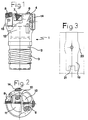
- a drilling tool 1 of the ejector type is provided with a shaft portion 2.
- the shaft portion 2 is provided with an outer thread 3, which, in a known way, is intended to threadably engage a retaining outer tube (not shown).
- the top part, crown or head of the drilling tool is provided with three cutting insert seats, which radially inwardly comprise a peripheral cutting insert 5, an intermediate insert 6 and a central insert 7.
- Each of these inserts is carried in a cartridge 8, 9 and 10, respectively.
- the peripheral insert 5 forms the diameter of the hole in the workpiece which is machined.
- the adjacent central insert 7 overlaps the central axis of the drill, as no remaining core is desired.
- the orbit of the cutting edge of the intermediate insert 6 overlaps with the cutting edges of both the peripheral insert 5 and the intermediate insert 6 to thereby obtain a continuous cutting line from the central axis to the periphery.
- chip flutes open on the top side of the drill; one larger chip flute 11 that is common for the peripheral insert 5 and the central insert 7, and another smaller chip flute 12 for the intermediate insert.
- the opposite lower ends of these chip flutes 11, 12 open in a turned-up inner chip space 13, which has the form of a frustocone with the bottom side turned upwards in the direction towards the top side of the drill.
- the peripheral cartridge 8 is provided with a supporting shim 15.
- the support pads 14 comprised of a cemented carbide body are provided.
- the support pads 14 each have a substantially parallelepiped basic shape with a rectangular or generally rectangular plan view.
- the pads 14 are defined by oppositely positioned longitudinal sides and oppositely positioned shorter lateral sides.
- Each of the support pads 14 is formed with two wing- shaped outgrowths 16, one on each longitudinal side of the pad.
- These protrusions, outgrowths or “wings” 16 each have substantially the form of two circle segments, which basically constitute mirror images of one another.
- the outer contour of each "wing” 16 essentially corresponds to a curved line and the "wings” 16 each extend laterally or radially outwardly with respect to the longitudinal dimension of the support pad 14.
- the longitudinal extension or length 1 of each of the "wings” 16 suitably constitutes between 1/5 and 3/5 of the total length L of the long side of the pad 14, preferably between 1/4 and the 1/2 of the total length L of the long side of the pad.
- the "wings" 16 are positioned intermediate the lateral sides of the pad, preferably at the center of the longitudinal extent of the support pads 14 as shown in Fig. 4.
- each support pad 14 is somewhat rounded to abut against the drilled hole in the workpiece.
- the edge lines of the support pads 14 are somewhat bevelled.
- the protrusions or "wings” are suitably made somewhat thinner than the thickness of the support pad.
- the support pad 14 is provided with a centrally located through central hole 18 for fixing of the support pad in the drill tool by a suitable locking screw.
- a seat 19 is provided in the drill head for accommodating the support pad 14 according to the present invention.
- the seat 19 has a substantially planar bottom.
- the two axial delimitations have two protuberant parts 20, whose form or shape substantially corresponds to the geometrical form of the two outgrowths or wing-shaped protrusions 16. In this way, it is quite easy to position the support pad 14 axially in the predetermined, desired position. To further facilitate the introduction of the support pad 14 into the seat, the latter may be provided with an axial lower abutment 21.
- the support pad and the support pad seat By the thus described construction of the support pad and the support pad seat, a number of advantages have been attained.
- a stronger support pad is obtained, particularly around the weakening that the through-hole 18 causes.
- the support pad 14 can be made entirely of cemented carbide - - a result which has not been possible according to the construction described in SE-C-347 450.
- Another advantage is that the axial abutment surfaces of the support pad consist of the contact surfaces between the wing-shaped protrusions 16 and the corresponding outgrowths 20 (the abutment 21 being optional). This provides a distinct advantage for damaged support pads. That is, a support pad which has been damaged at its one end may be loosened and turned one-half a revolution, since the shortside doesn't have to function as an abutment surface.
- the whole support pad seat 19 can easily be made with only one end mill.
- the whole support pad may be coated by a known PVD (Physical Vapour Deposition) or CVD (Chemical Vapour Deposition) technique.
- Another advantage is that the compacting of the cemented carbide powder is easier at the pressing of the support pads since the cross-sectional area is about the same along the whole length of the pad.
Landscapes
- Engineering & Computer Science (AREA)
- Mechanical Engineering (AREA)
- Drilling Tools (AREA)
- Earth Drilling (AREA)
- Processing Of Stones Or Stones Resemblance Materials (AREA)
- Perforating, Stamping-Out Or Severing By Means Other Than Cutting (AREA)
- Drilling And Boring (AREA)
Abstract
Description
- The present invention relates to a support pad for a drill, and to a drill provided with such a support pad. This drill includes one or several support pads arranged to support and to guide the drill in the drill hole. An example of a typical application for the support pad according to the invention is a drill tools of the ejector type. Advantageously, the support pad may be used for so called BTA-drilling. The U.S. patent document No. 3,751,177 represents the state of the art disclosing the features described in the first part of
claims 1 and 6. - In previously known drills, the support pads are fixedly joined with the drill by, for example, soldering, which causes some inconveniences. When the support pads are fixed, binding between the support pads and the hole may easily occur. In an attempt to avoid this problem to the extent possible, the pads can be made with a small conicity so that their distance from the drill axis diminishes somewhat in the rearward or backward direction, away from the tip. However this causes the pressure on the support pad to become concentrated on the front part of the pad, which is thus exposed to increased wear and greater heating. Another disadvantage of the aforementioned fixed support pads is the difficulty associated with obtaining full abutment between the pad and the drill in a tangential direction. Even if the drill diameter is constant, it is difficult to achieve a fit of the pad, which produces full contact.
- Another obvious disadvantage with fixed support pads is that if one of the pads becomes damaged, the whole drill must be replaced.
- According to Swedish patent document SE-C-347 450 (and U.S. Patent No. 3,751,177), an attempt has been made to address these disadvantages by replacing the fixed support pads with so-called swaying support pads. In accordance with the construction disclosed in this document, the pads are movably mounted in the drill so that they can turn both around a longitudinal axis and around a lateral axis. The ability of the pads to turn around the longitudinal axis is accomplished by an articulated joint included in the drill with a convex cylindrical sliding surface, which abuts against a corresponding convex sliding surface that forms a recess in the drill. These sliding surfaces have a longitudinal axis adjacent and somewhat outside the peripheral surface of the support pad. The outer surface of the joint is substantially flush with the drill's peripheral surface. Further, the joint is fastened in the drill by a screw. To permit the motions of the joint, there is a spring washer placed between the joint and the screw head.
- It has been discovered that this construction is susceptible of some disadvantages. In one respect, the construction it is relatively expensive and complicated to produce. Further, it has been found that it is very difficult to adjust it to different diameters. Furthermore, the construction is fragile and easily cracked, both in production and during use. When the support pad is damaged at its exposed short side, it is necessary to replace the support pad and the cradle.
- In view of the foregoing, it would be desirable to produce a drill which does not possess complicated support pad accommodating constructions, but which instead provides support pad fixations that comprise as few separate construction details as possible.
- It would also be desirable to provide a support pad which is strong and durable, and which can be produced entirely of cemented carbide.
- It would be further desirable to provide a drill whose support pads can make adjustment of different diameters possible.
- A need also exists for a drill whose support pads are easy to position and easy to machine.
- A further need also exists for a support pad that is designed in a way that allows damaged support pads to be reused.
- To address the foregoing needs, the present invention provides a surprisingly easy solution in which the support pads are provided with two wing-like protrusions. More particularly, in accordance with one aspect of the invention a support pad for a drilling tool comprises a cemented carbide body of a substantially parallelepiped shape with two longitudinal sides and two short sides. Each respective longitudinal side has a wing-shaped protrusion extending therefrom.
- According to another aspect of the invention, a drill for drilling a drill hole in a work piece comprises a drill head, at least one cutting insert seat provided on the drill head for accommodating a cutting insert, a support pad seat provided on the drill head, and a support pad accommodated in the support pad seat for supporting and guiding the drill. The support pad is comprised of a cemented carbide body of a substantially parallelepiped shape with oppositely positioned longitudinal sides, and a protrusion extends laterally from each of the longitudinal sides.
- For illustrative but non-limiting purposes, a preferred embodiment of the invention will be described with reference to the accompanying drawing figures in which like elements are designated by like reference numerals and wherein:
- Figure 1 is a side view, partially in section, of a drilling tool according to the present invention;
- Figure 2 is a top view of the drilling tool shown in figure 1;
- Figure 3 is a plan view of a support pad seat in a drilling tool;
- Figure 4 is a perspective view of a support pad according to the present invention;
- Figure 5 is a top view of the support pad shown o figure 4; and
- Figure 6 is a side view of the support pad shown in figure 4.
-
- As seen initially with reference to Fig. 1 a
drilling tool 1 of the ejector type is provided with ashaft portion 2. Theshaft portion 2 is provided with an outer thread 3, which, in a known way, is intended to threadably engage a retaining outer tube (not shown). - The top part, crown or head of the drilling tool is provided with three cutting insert seats, which radially inwardly comprise a
peripheral cutting insert 5, an intermediate insert 6 and a central insert 7. Each of these inserts is carried in acartridge 8, 9 and 10, respectively. However, the specific shapes of the cartridges and the inserts, respectively, do not constitute an essential feature for the present invention and the inserts can even for instance be soldered in the drill head in accordance with the disclosure contained in Swedish patent application 9402036-9.
Theperipheral insert 5 forms the diameter of the hole in the workpiece which is machined. The adjacent central insert 7 overlaps the central axis of the drill, as no remaining core is desired. During rotation, the orbit of the cutting edge of the intermediate insert 6 overlaps with the cutting edges of both theperipheral insert 5 and the intermediate insert 6 to thereby obtain a continuous cutting line from the central axis to the periphery. - Two chip flutes open on the top side of the drill; one larger chip flute 11 that is common for the
peripheral insert 5 and the central insert 7, and anothersmaller chip flute 12 for the intermediate insert. Preferably, the opposite lower ends of thesechip flutes 11, 12 open in a turned-upinner chip space 13, which has the form of a frustocone with the bottom side turned upwards in the direction towards the top side of the drill. According to the illustrated embodiment, also the peripheral cartridge 8 is provided with a supportingshim 15. - To support and guide the drill, two
support pads 14 comprised of a cemented carbide body are provided. Thesupport pads 14 each have a substantially parallelepiped basic shape with a rectangular or generally rectangular plan view. Thepads 14 are defined by oppositely positioned longitudinal sides and oppositely positioned shorter lateral sides. - Each of the
support pads 14 is formed with two wing-shaped outgrowths 16, one on each longitudinal side of the pad. These protrusions, outgrowths or "wings" 16 each have substantially the form of two circle segments, which basically constitute mirror images of one another. Thus, the outer contour of each "wing" 16 essentially corresponds to a curved line and the "wings" 16 each extend laterally or radially outwardly with respect to the longitudinal dimension of thesupport pad 14. The longitudinal extension orlength 1 of each of the "wings" 16 suitably constitutes between 1/5 and 3/5 of the total length L of the long side of thepad 14, preferably between 1/4 and the 1/2 of the total length L of the long side of the pad. The "wings" 16 are positioned intermediate the lateral sides of the pad, preferably at the center of the longitudinal extent of thesupport pads 14 as shown in Fig. 4. - As seen with reference to Fig. 6, the radial
outer side 17 of eachsupport pad 14 is somewhat rounded to abut against the drilled hole in the workpiece. To avoid potential jammings and bindings, the edge lines of thesupport pads 14 are somewhat bevelled. Also the protrusions or "wings" are suitably made somewhat thinner than the thickness of the support pad. Further, thesupport pad 14 is provided with a centrally located throughcentral hole 18 for fixing of the support pad in the drill tool by a suitable locking screw.
As depicted in Fig. 3, aseat 19 is provided in the drill head for accommodating thesupport pad 14 according to the present invention. Theseat 19 has a substantially planar bottom. The two axial delimitations have twoprotuberant parts 20, whose form or shape substantially corresponds to the geometrical form of the two outgrowths or wing-shapedprotrusions 16. In this way, it is quite easy to position thesupport pad 14 axially in the predetermined, desired position. To further facilitate the introduction of thesupport pad 14 into the seat, the latter may be provided with an axiallower abutment 21. - By the thus described construction of the support pad and the support pad seat, a number of advantages have been attained. By virtue of the two wing-shaped
protrusions 16, a stronger support pad is obtained, particularly around the weakening that the through-hole 18 causes. This means, inter alia, that thesupport pad 14 can be made entirely of cemented carbide - - a result which has not been possible according to the construction described in SE-C-347 450. Another advantage is that the axial abutment surfaces of the support pad consist of the contact surfaces between the wing-shapedprotrusions 16 and the corresponding outgrowths 20 (theabutment 21 being optional). This provides a distinct advantage for damaged support pads. That is, a support pad which has been damaged at its one end may be loosened and turned one-half a revolution, since the shortside doesn't have to function as an abutment surface. - Further, by means of the underlying shim layers of different thickness, different diameters may be easily set. These have then a plan view which substantially corresponds to that of the support pad and are laid under the support pad as a distance element. Besides, the whole
support pad seat 19 can easily be made with only one end mill. A further advantage is that the whole support pad may be coated by a known PVD (Physical Vapour Deposition) or CVD (Chemical Vapour Deposition) technique. - Another advantage is that the compacting of the cemented carbide powder is easier at the pressing of the support pads since the cross-sectional area is about the same along the whole length of the pad.
- The principles, preferred embodiments and modes of operation of the present invention have been described in the foregoing specification. However, the invention which is intended to be protected is not to be construed as limited to the particular embodiment disclosed. Further, the embodiment described herein is to be regarded as illustrative rather than restrictive. Variations and changes may be made by others, and equivalents employed, without departing from the scope of the present invention. Accordingly, it is expressly intended that all such changes, variations and equivalents which fall within the scope of the present invention as defined in the claims, be embraced thereby.
Claims (8)
- Support pad (14) positionable in a seat (19) provided in a drilling head of a drilling tool (1) to support and guide the tool, said support pad comprising a cemented carbide body of a substantially parallelepiped shape with oppositely positioned longitudinal sides and oppositely positioned lateral sides,
characterized in that a pair of protrusions (16) are provided, each of said protrusions (16) extending laterally from a respective one of said longitudinal sides at a position intermediate the lateral sides of the body, - Support pad (14) according to Claim 1, wherein each protrusion (16) possesses a shape of a segment of a circle.
- Support pad (14) according to Claims 1 or 2, wherein each protrusion (16) possesses a length as measured along the longitudinal extent of the support pad that is between 1/4 and 1/2 of the length of the longitudinal side.
- Support pad (14) according to Claims 1, 2 or 3, wherein an upper surface of the support pad is cylindrically rounded.
- Support pad (14) according to Claim 1 or 2, including a centrally located through hole (18) extending through the support pad (14).
- A drilling tool (1) for filling a drill hole in a workpiece, comprising a drill head, at least one cutting insert seat provided on the drill head for accommodating a cutting insert, a support pad seat (19) provided on the drill head, and a support pad (14) accommodated in the support pad seat (19) for supporting and guiding the drill, said support pad (14) being comprised of a cemented carbide body of substantially parallelepiped shape with oppositely positioned longitudinal sides and oppositely positioned lateral sides, characterized in that a pair of protrusions (16) are provided, each of said protrusions (16) extending laterally from each of said longitudinal sides at a position intermediate the lateral sides of the body.
- The drilling tool (1) according to Claim 6, wherein said support pad seat (19) includes two protuberances which each receive one of said protrusions.
- The drilling tool (1) according to Claim 6, wherein a hole extends through the support pad (14) and through the support pad seat (19).
Applications Claiming Priority (3)
| Application Number | Priority Date | Filing Date | Title |
|---|---|---|---|
| SE9403024 | 1994-09-12 | ||
| SE9403024A SE504331C2 (en) | 1994-09-12 | 1994-09-12 | Support bar for drill |
| PCT/SE1995/001015 WO1996008332A1 (en) | 1994-09-12 | 1995-09-11 | Support pad for drill |
Publications (2)
| Publication Number | Publication Date |
|---|---|
| EP0781183A1 EP0781183A1 (en) | 1997-07-02 |
| EP0781183B1 true EP0781183B1 (en) | 2000-08-23 |
Family
ID=20395191
Family Applications (1)
| Application Number | Title | Priority Date | Filing Date |
|---|---|---|---|
| EP95932273A Expired - Lifetime EP0781183B1 (en) | 1994-09-12 | 1995-09-11 | Support pad for drill |
Country Status (12)
| Country | Link |
|---|---|
| US (1) | US5697737A (en) |
| EP (1) | EP0781183B1 (en) |
| JP (1) | JP3700860B2 (en) |
| KR (1) | KR100373816B1 (en) |
| CN (1) | CN1066370C (en) |
| AT (1) | ATE195682T1 (en) |
| CA (1) | CA2198370C (en) |
| DE (1) | DE69518530T2 (en) |
| ES (1) | ES2150007T3 (en) |
| RU (1) | RU2136450C1 (en) |
| SE (1) | SE504331C2 (en) |
| WO (1) | WO1996008332A1 (en) |
Families Citing this family (25)
| Publication number | Priority date | Publication date | Assignee | Title |
|---|---|---|---|---|
| SE509383C2 (en) * | 1994-06-13 | 1999-01-18 | Sandvik Ab | drilling Tools |
| US5947657A (en) * | 1998-08-14 | 1999-09-07 | Kennametal Inc. | Drill jig assembly having hydraulic chuck and drill guide with pilot bore |
| US6260636B1 (en) | 1999-01-25 | 2001-07-17 | Baker Hughes Incorporated | Rotary-type earth boring drill bit, modular bearing pads therefor and methods |
| SE517446C2 (en) * | 1999-06-21 | 2002-06-04 | Sandvik Ab | Support pad / Conductor |
| DE10209924A1 (en) * | 2002-03-07 | 2003-09-25 | Beck August Gmbh Co | Guide bar for strip-guided cutting tools |
| DE20219754U1 (en) * | 2002-12-19 | 2004-04-22 | Gühring, Jörg, Dr. | Deep hole drill with exchangeable cutting insert and exchangeable guide bar |
| DE10315394A1 (en) * | 2003-04-04 | 2004-11-04 | Sandvik Ab | boring tool |
| SE526567C2 (en) * | 2003-07-16 | 2005-10-11 | Sandvik Intellectual Property | Support bar for long hole drill with wear surface in different color |
| SE527809C2 (en) * | 2004-06-21 | 2006-06-13 | Sandvik Intellectual Property | Support moldings for drill heads |
| RU2345870C1 (en) * | 2007-04-24 | 2009-02-10 | Государственное образовательное учреждение высшего профессионального образования Липецкий государственный технический университет (ЛГТУ) | Deep boring attachment |
| SE533277C2 (en) * | 2008-12-19 | 2010-08-10 | Sandvik Intellectual Property | Drill body and support strip for this |
| SE0950096A1 (en) * | 2009-02-20 | 2010-07-06 | Seco Tools Ab | Control arrangement for a cutting tool and cutting tool which includes a control arrangement |
| DE102010018959A1 (en) * | 2010-04-23 | 2011-10-27 | Tbt Tiefbohrtechnik Gmbh + Co | Drilling head for a deep drilling tool for BTA deep drilling and deep hole drilling tool |
| CN103402677B (en) | 2011-02-28 | 2015-11-25 | 株式会社钨钛合金 | Guide pad, cutting element main body and cutting element |
| EP2682211A1 (en) * | 2011-02-28 | 2014-01-08 | Tungaloy Corporation | Guide pad, cutting tool body, and cutting tool |
| DE102011017399B4 (en) * | 2011-04-18 | 2025-09-18 | Gustav Werthwein | Countersinking tool for producing cylindrical holes |
| JP5957522B2 (en) | 2011-06-13 | 2016-07-27 | イスカーリミテッド | Cutting tool, cutting tool body, and cutting tool support pad therefor |
| EP2700463B1 (en) | 2012-08-22 | 2016-10-12 | Sandvik Intellectual Property AB | Method for manufacturing a support pad |
| KR101674334B1 (en) * | 2012-12-28 | 2016-11-08 | 한국야금 주식회사 | A support pad for deep hole indexable drill |
| KR101696564B1 (en) * | 2012-12-28 | 2017-01-13 | 한국야금 주식회사 | Drill tools having Pad and drill head |
| JP5655234B2 (en) * | 2013-01-09 | 2015-01-21 | 国立大学法人九州大学 | Guide part arrangement structure and guide part arrangement method of cutting tool for cutting |
| EP2862655A1 (en) | 2013-10-16 | 2015-04-22 | Sandvik Intellectual Property AB | A guide pad and a cutter head for a cutting tool |
| WO2017018422A1 (en) * | 2015-07-27 | 2017-02-02 | 株式会社タンガロイ | Cutting tool replacement member and cutting tool body |
| US10201861B2 (en) | 2017-02-21 | 2019-02-12 | Iscar, Ltd. | Hole machining tool and guide pad adjustment mechanism therefor |
| JP7150254B1 (en) * | 2022-05-02 | 2022-10-11 | 株式会社タンガロイ | Guide pads and gundrills with guide pads |
Family Cites Families (9)
| Publication number | Priority date | Publication date | Assignee | Title |
|---|---|---|---|---|
| DE251932C (en) * | ||||
| DE729898C (en) * | 1936-03-15 | 1943-01-04 | Mitteldeutsche Stahlwerke Ag | Deep drill for running boring bars |
| SE347450B (en) * | 1969-11-24 | 1972-08-07 | Sandvikens Jernverks Ab | |
| DE7812666U1 (en) * | 1978-04-26 | 1978-09-21 | Ledermann Gmbh + Co, 7240 Horb | DRILLING TOOL |
| DE2821658A1 (en) * | 1978-05-18 | 1979-11-22 | Hegenscheidt Gmbh Wilhelm | Metal boring head with cutter bits - has guide strips providing self alignment to avoid run out of bore |
| DE2833778A1 (en) * | 1978-08-02 | 1980-02-14 | Sitzmann & Heinlein | Boring head guide with wear resistant slider - has replaceable sliding piece held by clamping screws and springs |
| SU1263440A1 (en) * | 1982-04-27 | 1986-10-15 | Предприятие П/Я Р-6760 | Guide of composite tool for working deep holes |
| SU1366318A1 (en) * | 1986-03-18 | 1988-01-15 | Ленинградский механический институт им.Маршала Советского Союза Устинова Д.Ф. | Tool provided with mechanical securing of guide components |
| SU1726154A1 (en) * | 1990-04-27 | 1992-04-15 | Научно-Производственное Объединение "Спецтехоснастка" | Boring head |
-
1994
- 1994-09-12 SE SE9403024A patent/SE504331C2/en not_active IP Right Cessation
-
1995
- 1995-09-11 ES ES95932273T patent/ES2150007T3/en not_active Expired - Lifetime
- 1995-09-11 RU RU97105850/02A patent/RU2136450C1/en active
- 1995-09-11 KR KR1019970701591A patent/KR100373816B1/en not_active Expired - Lifetime
- 1995-09-11 CN CN95194905A patent/CN1066370C/en not_active Expired - Lifetime
- 1995-09-11 WO PCT/SE1995/001015 patent/WO1996008332A1/en not_active Ceased
- 1995-09-11 US US08/526,390 patent/US5697737A/en not_active Expired - Lifetime
- 1995-09-11 AT AT95932273T patent/ATE195682T1/en active
- 1995-09-11 DE DE69518530T patent/DE69518530T2/en not_active Expired - Lifetime
- 1995-09-11 CA CA002198370A patent/CA2198370C/en not_active Expired - Lifetime
- 1995-09-11 EP EP95932273A patent/EP0781183B1/en not_active Expired - Lifetime
- 1995-09-11 JP JP51010796A patent/JP3700860B2/en not_active Expired - Lifetime
Also Published As
| Publication number | Publication date |
|---|---|
| RU2136450C1 (en) | 1999-09-10 |
| US5697737A (en) | 1997-12-16 |
| EP0781183A1 (en) | 1997-07-02 |
| CN1066370C (en) | 2001-05-30 |
| KR100373816B1 (en) | 2003-06-09 |
| SE504331C2 (en) | 1997-01-13 |
| JPH10505548A (en) | 1998-06-02 |
| ATE195682T1 (en) | 2000-09-15 |
| CA2198370A1 (en) | 1996-03-21 |
| SE9403024L (en) | 1996-03-13 |
| SE9403024D0 (en) | 1994-09-12 |
| ES2150007T3 (en) | 2000-11-16 |
| JP3700860B2 (en) | 2005-09-28 |
| CA2198370C (en) | 2005-08-16 |
| CN1156981A (en) | 1997-08-13 |
| KR970705447A (en) | 1997-10-09 |
| DE69518530D1 (en) | 2000-09-28 |
| WO1996008332A1 (en) | 1996-03-21 |
| DE69518530T2 (en) | 2001-01-11 |
Similar Documents
| Publication | Publication Date | Title |
|---|---|---|
| US5697737A (en) | Support pad for drill | |
| CA2484602C (en) | Rotary cutting tool comprising an exchangeable cutting insert | |
| EP0874706B1 (en) | Tool for cutting machining | |
| US6551035B1 (en) | Tool for rotary chip removal, a tool tip and a method for manufacturing a tool tip | |
| US5863162A (en) | Tool body and removable tool tip for chip removing machining | |
| EP1163966B1 (en) | Tool tip for drill | |
| US8696269B2 (en) | Drill body as well as support pad therefor | |
| EP0781184B1 (en) | Drilling tool | |
| US7513721B2 (en) | Deburring tool | |
| WO1992012817A1 (en) | Indexable insert drill and an insert with a symmetrical drill point and cutting edges of different lengths | |
| KR20100138803A (en) | Loose tower for chip removal machining tools and tooth drilling tools | |
| JP3911934B2 (en) | Reamer | |
| CZ6622U1 (en) | Tool unit for reaming precise holes |
Legal Events
| Date | Code | Title | Description |
|---|---|---|---|
| PUAI | Public reference made under article 153(3) epc to a published international application that has entered the european phase |
Free format text: ORIGINAL CODE: 0009012 |
|
| 17P | Request for examination filed |
Effective date: 19970215 |
|
| AK | Designated contracting states |
Kind code of ref document: A1 Designated state(s): AT BE CH DE DK ES FR GB IE IT LI LU NL PT SE |
|
| 17Q | First examination report despatched |
Effective date: 19981102 |
|
| GRAG | Despatch of communication of intention to grant |
Free format text: ORIGINAL CODE: EPIDOS AGRA |
|
| GRAG | Despatch of communication of intention to grant |
Free format text: ORIGINAL CODE: EPIDOS AGRA |
|
| GRAH | Despatch of communication of intention to grant a patent |
Free format text: ORIGINAL CODE: EPIDOS IGRA |
|
| GRAH | Despatch of communication of intention to grant a patent |
Free format text: ORIGINAL CODE: EPIDOS IGRA |
|
| GRAA | (expected) grant |
Free format text: ORIGINAL CODE: 0009210 |
|
| AK | Designated contracting states |
Kind code of ref document: B1 Designated state(s): AT BE CH DE DK ES FR GB IE IT LI LU NL PT SE |
|
| PG25 | Lapsed in a contracting state [announced via postgrant information from national office to epo] |
Ref country code: NL Free format text: LAPSE BECAUSE OF FAILURE TO SUBMIT A TRANSLATION OF THE DESCRIPTION OR TO PAY THE FEE WITHIN THE PRESCRIBED TIME-LIMIT Effective date: 20000823 Ref country code: LI Free format text: LAPSE BECAUSE OF FAILURE TO SUBMIT A TRANSLATION OF THE DESCRIPTION OR TO PAY THE FEE WITHIN THE PRESCRIBED TIME-LIMIT Effective date: 20000823 Ref country code: CH Free format text: LAPSE BECAUSE OF FAILURE TO SUBMIT A TRANSLATION OF THE DESCRIPTION OR TO PAY THE FEE WITHIN THE PRESCRIBED TIME-LIMIT Effective date: 20000823 Ref country code: BE Free format text: LAPSE BECAUSE OF FAILURE TO SUBMIT A TRANSLATION OF THE DESCRIPTION OR TO PAY THE FEE WITHIN THE PRESCRIBED TIME-LIMIT Effective date: 20000823 Ref country code: AT Free format text: LAPSE BECAUSE OF FAILURE TO SUBMIT A TRANSLATION OF THE DESCRIPTION OR TO PAY THE FEE WITHIN THE PRESCRIBED TIME-LIMIT Effective date: 20000823 |
|
| REF | Corresponds to: |
Ref document number: 195682 Country of ref document: AT Date of ref document: 20000915 Kind code of ref document: T |
|
| REG | Reference to a national code |
Ref country code: CH Ref legal event code: EP |
|
| PG25 | Lapsed in a contracting state [announced via postgrant information from national office to epo] |
Ref country code: LU Free format text: LAPSE BECAUSE OF NON-PAYMENT OF DUE FEES Effective date: 20000911 Ref country code: IE Free format text: LAPSE BECAUSE OF NON-PAYMENT OF DUE FEES Effective date: 20000911 |
|
| REG | Reference to a national code |
Ref country code: IE Ref legal event code: FG4D |
|
| REF | Corresponds to: |
Ref document number: 69518530 Country of ref document: DE Date of ref document: 20000928 |
|
| ITF | It: translation for a ep patent filed | ||
| REG | Reference to a national code |
Ref country code: ES Ref legal event code: FG2A Ref document number: 2150007 Country of ref document: ES Kind code of ref document: T3 |
|
| PG25 | Lapsed in a contracting state [announced via postgrant information from national office to epo] |
Ref country code: SE Free format text: LAPSE BECAUSE OF FAILURE TO SUBMIT A TRANSLATION OF THE DESCRIPTION OR TO PAY THE FEE WITHIN THE PRESCRIBED TIME-LIMIT Effective date: 20001123 Ref country code: PT Free format text: LAPSE BECAUSE OF FAILURE TO SUBMIT A TRANSLATION OF THE DESCRIPTION OR TO PAY THE FEE WITHIN THE PRESCRIBED TIME-LIMIT Effective date: 20001123 Ref country code: DK Free format text: LAPSE BECAUSE OF FAILURE TO SUBMIT A TRANSLATION OF THE DESCRIPTION OR TO PAY THE FEE WITHIN THE PRESCRIBED TIME-LIMIT Effective date: 20001123 |
|
| ET | Fr: translation filed | ||
| NLV1 | Nl: lapsed or annulled due to failure to fulfill the requirements of art. 29p and 29m of the patents act | ||
| REG | Reference to a national code |
Ref country code: CH Ref legal event code: PL |
|
| PLBE | No opposition filed within time limit |
Free format text: ORIGINAL CODE: 0009261 |
|
| STAA | Information on the status of an ep patent application or granted ep patent |
Free format text: STATUS: NO OPPOSITION FILED WITHIN TIME LIMIT |
|
| REG | Reference to a national code |
Ref country code: IE Ref legal event code: MM4A |
|
| 26N | No opposition filed | ||
| REG | Reference to a national code |
Ref country code: GB Ref legal event code: IF02 |
|
| REG | Reference to a national code |
Ref country code: GB Ref legal event code: 732E |
|
| REG | Reference to a national code |
Ref country code: GB Ref legal event code: 732E |
|
| REG | Reference to a national code |
Ref country code: FR Ref legal event code: TP |
|
| REG | Reference to a national code |
Ref country code: FR Ref legal event code: TP |
|
| PGFP | Annual fee paid to national office [announced via postgrant information from national office to epo] |
Ref country code: DE Payment date: 20140903 Year of fee payment: 20 |
|
| PGFP | Annual fee paid to national office [announced via postgrant information from national office to epo] |
Ref country code: GB Payment date: 20140910 Year of fee payment: 20 Ref country code: ES Payment date: 20140812 Year of fee payment: 20 |
|
| PGFP | Annual fee paid to national office [announced via postgrant information from national office to epo] |
Ref country code: IT Payment date: 20140912 Year of fee payment: 20 |
|
| PGFP | Annual fee paid to national office [announced via postgrant information from national office to epo] |
Ref country code: FR Payment date: 20140906 Year of fee payment: 20 |
|
| REG | Reference to a national code |
Ref country code: DE Ref legal event code: R071 Ref document number: 69518530 Country of ref document: DE |
|
| REG | Reference to a national code |
Ref country code: GB Ref legal event code: PE20 Expiry date: 20150910 |
|
| PG25 | Lapsed in a contracting state [announced via postgrant information from national office to epo] |
Ref country code: GB Free format text: LAPSE BECAUSE OF EXPIRATION OF PROTECTION Effective date: 20150910 |
|
| REG | Reference to a national code |
Ref country code: ES Ref legal event code: FD2A Effective date: 20151229 |
|
| PG25 | Lapsed in a contracting state [announced via postgrant information from national office to epo] |
Ref country code: ES Free format text: LAPSE BECAUSE OF EXPIRATION OF PROTECTION Effective date: 20150912 |