EP0780294B1 - Space module - Google Patents
Space module Download PDFInfo
- Publication number
- EP0780294B1 EP0780294B1 EP96120411A EP96120411A EP0780294B1 EP 0780294 B1 EP0780294 B1 EP 0780294B1 EP 96120411 A EP96120411 A EP 96120411A EP 96120411 A EP96120411 A EP 96120411A EP 0780294 B1 EP0780294 B1 EP 0780294B1
- Authority
- EP
- European Patent Office
- Prior art keywords
- base
- attached
- module
- space
- side walls
- Prior art date
- Legal status (The legal status is an assumption and is not a legal conclusion. Google has not performed a legal analysis and makes no representation as to the accuracy of the status listed.)
- Expired - Lifetime
Links
Images





Classifications
-
- B—PERFORMING OPERATIONS; TRANSPORTING
- B64—AIRCRAFT; AVIATION; COSMONAUTICS
- B64G—COSMONAUTICS; VEHICLES OR EQUIPMENT THEREFOR
- B64G1/00—Cosmonautic vehicles
- B64G1/10—Artificial satellites; Systems of such satellites; Interplanetary vehicles
- B64G1/1007—Communications satellites
-
- B—PERFORMING OPERATIONS; TRANSPORTING
- B64—AIRCRAFT; AVIATION; COSMONAUTICS
- B64G—COSMONAUTICS; VEHICLES OR EQUIPMENT THEREFOR
- B64G1/00—Cosmonautic vehicles
- B64G1/22—Parts of, or equipment specially adapted for fitting in or to, cosmonautic vehicles
-
- B—PERFORMING OPERATIONS; TRANSPORTING
- B64—AIRCRAFT; AVIATION; COSMONAUTICS
- B64G—COSMONAUTICS; VEHICLES OR EQUIPMENT THEREFOR
- B64G1/00—Cosmonautic vehicles
- B64G1/22—Parts of, or equipment specially adapted for fitting in or to, cosmonautic vehicles
- B64G1/223—Modular spacecraft systems
Definitions
- the present invention relates to a space module comprising a base; one or more side walls attached to said base; and a top panel attached to said one or more side walls, wherein said base, said one or more side walls and said top panel enclose an interior volume of space, wherein said volume of space is physically divided into a first area and a second area, wherein said first and second areas are thermally and structurally segregated from one another and wherein a plurality of side walls attached to that base is provided so that a cross-section of said side walls taken parallel to that base defines a polygon having two or more diagonals.
- US 5,314,146 discloses a multi-mission spacecraft bus structure which has a plurality of internal thermally-isolated cells, and a plurality of external mounting surfaces.
- the spacecraft bus structure comprises a plurality of half-frame panels, which are secured to a plurality of longerons.
- the half-frame panels each have a pair of broad planar surfaces, a center abutting surface, a pair of end-abutting surfaces, and a pair of miter joint surfaces.
- the bus structure is further sealed at the top and at the bottom by mounting plates.
- External electrical equipment bays can be secured to a plurality of the external mounting surfaces.
- Externally mounted radiators are provided to remove excess heat from the internal cells.
- US 4,324,375 discloses a spacecraft modular system with two components of a cooling system, one in each replacement hardware module and one in the satellite station, with a coupling means in the replacement module in the form of heat sink which collects heat from the heat generating hardware in the replacement module.
- spacecraft satellites are manufactured by housing the payload in bus systems within a common module.
- the manufacture of these modules is interdependent with a payload unit layout with respect to the thermal, power, signal, packaging, etc. systems onboard the spacecraft.
- Interdependence of bus and payload units, in current designs, is such that new payload layouts effect bus unit layouts. This is undesirable from the standpoint of the redesign of bus unit layouts and support structure, which requires non-recurring and recurring costs, and increased cycle time.
- the interdependence of the bus and payload unit layouts requires integrated tooling, assembly, testing and alignment of the satellite as a whole. This method does not allow construction of spacecraft until all bus and payload related requirements are satisfied, negating the opportunity for advance ordering and building of any of the spacecraft subsystems.
- spacecraft modules Although the manufacture of spacecraft modules has been adequate, there are of course areas that produce improvement. For example, segregation into separate modules result in parallel production, testing and a standard bus that can be fabricated in advance and in an efficient time frame. This permits a smaller factory to process the required capacities and reduces long lead times for completing the manufacture of a spacecraft. This individualized manufacturing will result in a decrease in hardware and labor costs.
- the present invention provides a standardized space module to which a standardized aft end of a payload module is attached. More particularly, the present invention concerns a space module having a base in one or more side walls attached to the base. A top panel is attached to the one or more side walls so that the base, the one or more side walls and the interface enclose an interior volume of space which is physically divided into a first area and a second area which are thermally and structurally segregated from one another. A support wall is provided within that interior volume of space and along the entire length of one of said diagonals and attached to said base and said top panel.
- the top panel has a structure designed to receive and attach itself to a substantial number of known satellite payload modules.
- the above-described space module structure allows for increased factory capacities of spacecraft or satellites.
- the disclosed invention will reduce the hardware and labor needed to complete a spacecraft or satellite so that the time to manufacture a satellite or spacecraft will be reduced.
- Satellite 20 has a spacecraft body 22 which includes a lower bus module 24 and an upper payload module 26. Attached to the aft end of the lower bus module 24 are a plurality of engines. These engines include a centrally positioned liquid orbital thruster (not shown) and four pairs of chemical propulsion engines 28 located at the corners of the bus module 24 and two pairs of xenon ion propulsion engines 30. Lower bus module 24 contains one or more fuel tanks 32 and various power and control modules which operate the propulsion system and power the payload module 26. Bus module 24 further includes a pair of solar panels 34 which convert sunlight into electricity which is sent to batteries (not shown) located on the bus module 24. Bus module 24 also has one or more antennae 36, and reflectors 38 which receive signals from one or more ground stations on Earth which are used to control the satellite 20. Antennae 36 and reflectors 38 also send signals to the ground stations.
- Payload module 26 is attached to the bus module 24 and contains a variety of electronic equipment which may contain a number of sensors (not shown).
- the electronic equipment processes information gathered by the sensors and sends the processed information back to the ground stations via antennae 36 and reflectors 38.
- the gathered information may concern communications, weather observation, navigational information, etc.
- spacecraft 20 is initially in a stored configuration when loaded on the launch vehicle 40.
- all peripheral components such as the solar panels 34 and the antennae 36 are folded up to be adjacent to the spacecraft body 22.
- the peripheral components remain in their folded condition when the spacecraft 20 leaves the launch vehicle 40 and moves into a desired orbit. Once in the desired orbit, the peripheral elements are unfolded as shown in FIG. 1.
- spacecraft body 22 supports the peripheral elements is the spacecraft body 22 as shown in FIG. 3.
- spacecraft body 22 includes a bus module 24 and a payload module 26.
- Base 42 has a perimeter 48 with four sides 50 which define a polygon, such as a rectangle or a square.
- perimeter 48 has a length of approximately 175" and a width of approximately 100".
- Attached to the base 42 are four side walls 52, 54, 56 and 58. Side walls 52 and 54 face opposite each other and are attached to and positioned substantially perpendicular to sides 50.
- side walls 56 and 58 are substantially perpendicular to and attached to base 42.
- Side walls 56 and 58 preferably lie approximately 12" from the perimeter 48 and are attached to side walls 52 and 54 so that a cross-section of the four side walls taken parallel to base 42 forms a polygon having two or more diagonals, such as a rectangle or a square.
- a pair of exterior panels 60, 62 are attached to the ends of side walls 52 and 54 so that exterior panels 60 and 62 are parallel to and face side panels 56 and 58, respectively.
- the exterior panels 60 and 62 have a rectangular shape having a length of approximately 75" and a width of approximately 36". Panels 60 and 62 may be hinged or permanently attached. Attachment of the four side walls.
- a top panel or interface 64 is then attached, via a mechanical fastener, to all four side walls so that base 42, side walls 52, 54, 56, 58 and interface 64 enclose an interior volume of space.
- one or more fuel tanks 32 are located within the interior volume of space.
- four of the fuel tanks 32 are in fluid communication with a main orbital engine (not shown) attached to the base 42 so that fuel is fed to the engine.
- the main orbital engine propels the satellite 20 into the proper orbit after the satellite 20 has left the launch vehicle 40.
- the main orbital thruster is supported on a pyramid-like plume shield 66 which has four panels 68 which extend upward through opening 44.
- Plume shield 66 is made of a titanium material with a nickel foil and quartz layer located on the exterior.
- plume 66 has a height of approximately and a square bottom base having sides with a length of approximately 45".
- Panels 68 are welded to each other and form a square opening 70 through which the nozzle 46 passes.
- Panels 68 are also attached to corresponding metal bars 72 which are attached to the underside of base 42.
- Metal bars 72 are attached to base 42 and to four fittings 74 by mechanical fasteners. Fittings 74 are likewise mechanically attached to the corner slots 76 of opening 44.
- the interface 64 is also mechanically attached to the exterior panels 60 and 62 so that a volume of space is defined by base 42, interface 64 and exterior panels 60 and 62.
- side walls 56 and 58 physically divide the volume of space into three areas I, II, and III, wherein each area is thermally, environmentally (i.e. micrometeorite shielding and Faraday cage) and structurally segregated from one another.
- the inner area I contains the main orbital engine and fuel tanks 32.
- Areas II and III contain power system components 78 and attitude control system components 80.
- the power system components 78 and the attitude control system components 80 may be thermally, environmentally, and structurally segregated from each other as well by a hinged shelf 82 which is hingedly attached to a side wall 56, 58 so that it can move from a stored position adjacent to side wall 56, 58 to a deployed position where the shelf is parallel to base 42 so that it can support components 80 thereon.
- shelf 82 can be hinged to a side wall 56, 58 so that it will be vertical to both side walls 56, 58 and base 42 when it moves to a deployed position.
- a shelf 82 positioned parallel to base 42 may be movable so that the distance from the shelf 82 to base 42 can be varied. As shown in FIG. 8, this is accomplished by attaching the shelf 82 to one of a multiple number of connectors, such as holes 84, which extend from the base 42 to interface 64. It is understood that shelf 82 also may be permanently attached to walls 52, 54, 56, 58 and exterior panels 60 and 62.
- area I pertains to a volume of space bounded by base 42, interface 64 and side walls 52, 54, 56 and 58.
- a cross-section of side walls 52, 54, 56 and 58 taken parallel to base 42 defines a polygon having two or more diagonals, such as a rectangle or a square.
- a pair of support walls 86, 88 are attached to base 42 via U-shaped fitting 90 (or via bonding) which are attached to fittings 74.
- the support walls 86, 88 are also attached to interface 64 and side walls 52, 54, 56 and 58 so that the entire length of the support walls lie along the entire length of each diagonal.
- Each support wall 86, 88 can be either of one piece or two piece construction.
- both halves of the support wall are attached to each other at the center of the volume of space by a bottom piece 92 and a top piece 94 which have slots to receive the halves, as shown in FIG. 9.
- the bottom and top pieces 92 and 94 are welded to each of the halves.
- the support walls 86, 88 so constructed preferably intersect one another at approximately 90° and define four areas which have a fuel tank 32, as shown in FIG. 10.
- base 42, interface 64, side walls 52, 54, 56 and 58, support walls 86, 88, shelves 82 and panels 60 and 62 are preferably made of a suitable metallic and/or composite material, such as Kevlar or graphite, or by a process as described in U.S. Patent No. 5,273,806, whose contents are incorporated herein by reference.
- a number of apertures can be formed in the base, interface, side walls, support walls and panels, so that the weight of the bus module 24 is reduced.
- the shape of the apertures can take on various forms.
- An alternative shape for the apertures of interface 64 is shown in FIG. 11.
- Fuel tanks 32 are further secured within bus module 24 by four collars 96 on flexible interface 64 which are attached via bolts to an annular surface of the fuel tank 14.
- interface 64 has a standardized structure designed to receive and attach itself to a standard aft end of a satellite payload module 26.
- the interface 64 has one or more attachment elements or engagement elements 98 which are always arranged thereon in a predetermined and standard pattern so that they receive one or more connection elements from a standard aft end 100 of a satellite payload module 26.
- the bus module 28 has an electrical port, such as an electrical pin connector, located at each corner of the interface 64 and near the engagement elements 98.
- the bus module or payload module can contain one or more voltage converters which can assure that the electrical voltages passed from the bus module to the payload module and vice versa are compatible.
- the purpose of standardizing the structure of the interface 64 and the aft end of the payload module 26 is to allow attachment between a bus module with any payload module. This would allow for the bus and payload modules to be manufactured in different locations and by different corporate entities without worrying whether attachment will be achieved between the modules.
- FIGS. 3 and 12-14 an embodiment of a payload module 26 is shown in FIGS. 3 and 12-14 which has an aft end or base 100 which always has an attachment device 102, such as a standard cone and socket attachment, arranged thereon at a position which corresponds to any one of the predetermined and standard locations on interface 64 which possess an engagement device 98.
- the bus module 24 is attached to payload module 26 by having the attachment device 102 of the payload module 26 engage with a corresponding engagement element or device 98 of the bus module 24.
- the number of predetermined and standard locations on the interface must be at least as large as the number of attachment devices 102 on the payload module 26.
- the payload module 26 is electrically powered via a power bus 104 attached to both modules.
- Payload module 26 has four side walls 106 that are attached to base 100 and which meet at four corners. At each corner are a pair of connectors (not shown) or hinges (not shown) which are hingedly attached to a heat radiator 108 via a pivot member so that the heat radiator 108 is able to rotate about an axis A.
- Base 100 has a perimeter 110 with four sides 112 which define a polygon, such as a rectangle or a square.
- perimeter 110 matches the perimeter of interface 64 so that it has a length of approximately 100" and a width of approximately 75".
- Side walls 106 are attached to and positioned substantially perpendicular to sides 112.
- a top panel 114 is then mechanically attached to all four side walls 106 so that base 100, side walls 106 and top panel 114 enclose an interior volume of space in which the payload is located. Attachment of the four side walls 106 to base 100 is accomplished in a well known manner, such as bolts or bonding.
- a pair of support walls 116 are attached to base 100 so that they are perpendicular to sides 112 and perpendicular to each other. Attachment is accomplished in a well known manner by way of brackets 118 which are attached along the length and width of oppositely facing side walls 106, as shown in FIG. 13. Support walls 116 in conjunction with side walls 106, base 100 and top panel 114 form four thermally, environmentally and structurally segregated areas I. II, III, IV. As with the bus module 24, the number of segregated areas can be increased by adding one or more shelves 118, as shown in FIGS. 13 and 14. Shelves 118 are attached as and can take on the structure of any of the embodiments of shelf 80 of bus module 24 as described above.
- the base 100, top panel 114, side walls 106 and shelves 118 are preferably made by a process as described in U.S. Patent No. 5,273,806.
- a number of apertures can be formed in the base, top panels, side walls, and support walls, so that the weight of the payload module 26 is reduced.
- the bus module 24 and/or the payload module 26 may have a cylindrical shape.
- the base 120 of such a bus module 24 has circular perimeter 122 which is attached to an inner side wall 124 and an exterior side wall 126. Attached to the inner and outer side walls is a circular interface 128 having the standardized pattern of attachment devices as described above for interface 64.
- the side walls define two areas I and II which are structurally and thermally isolated from one another.
- area I can contain one or more fuel tanks 32 which are separated from one another by a pair of support walls 130 which lie along the entire length of diameters of the circular perimeter.
- the support walls are angled at 90° to each other and are attached as previously described for the embodiment of FIGS. 1-14.
- a cylindrical pay load module 26 (see FIGS. 15 and 16B) would have a circular standard aft end or base 132 which is structured like base 100 described above, so as to allow for standardized connection with interface 128.
- a pair of side wall 134, 136 and a pair of support walls 138, 140 are attached to base 132 and a circular top panel 142 in the manner as described above for the payload module of FIGS. 1-14.
- the present invention provides an improved structure for a payload module and a bus module.
- the present invention leads to a way of more efficiently constructing satellites by standardizing the attachment between payload and bus modules.
- the present invention regards a modular design which provides for improved installation of components on a spacecraft by segregating the components thermally, environmentally and structurally.
Landscapes
- Engineering & Computer Science (AREA)
- Remote Sensing (AREA)
- Aviation & Aerospace Engineering (AREA)
- Physics & Mathematics (AREA)
- Astronomy & Astrophysics (AREA)
- General Physics & Mathematics (AREA)
- Casings For Electric Apparatus (AREA)
- Aerials With Secondary Devices (AREA)
- Body Structure For Vehicles (AREA)
Description
- The present invention relates to a space module comprising a base; one or more side walls attached to said base; and a top panel attached to said one or more side walls, wherein said base, said one or more side walls and said top panel enclose an interior volume of space, wherein said volume of space is physically divided into a first area and a second area, wherein said first and second areas are thermally and structurally segregated from one another and wherein a plurality of side walls attached to that base is provided so that a cross-section of said side walls taken parallel to that base defines a polygon having two or more diagonals.
- US 5,314,146 discloses a multi-mission spacecraft bus structure which has a plurality of internal thermally-isolated cells, and a plurality of external mounting surfaces. The spacecraft bus structure comprises a plurality of half-frame panels, which are secured to a plurality of longerons. The half-frame panels each have a pair of broad planar surfaces, a center abutting surface, a pair of end-abutting surfaces, and a pair of miter joint surfaces. The bus structure is further sealed at the top and at the bottom by mounting plates. External electrical equipment bays can be secured to a plurality of the external mounting surfaces. Externally mounted radiators are provided to remove excess heat from the internal cells.
- US 4,324,375 discloses a spacecraft modular system with two components of a cooling system, one in each replacement hardware module and one in the satellite station, with a coupling means in the replacement module in the form of heat sink which collects heat from the heat generating hardware in the replacement module.
- Currently, spacecraft satellites are manufactured by housing the payload in bus systems within a common module. The manufacture of these modules is interdependent with a payload unit layout with respect to the thermal, power, signal, packaging, etc. systems onboard the spacecraft. Interdependence of bus and payload units, in current designs, is such that new payload layouts effect bus unit layouts. This is undesirable from the standpoint of the redesign of bus unit layouts and support structure, which requires non-recurring and recurring costs, and increased cycle time. Furthermore, the interdependence of the bus and payload unit layouts requires integrated tooling, assembly, testing and alignment of the satellite as a whole. This method does not allow construction of spacecraft until all bus and payload related requirements are satisfied, negating the opportunity for advance ordering and building of any of the spacecraft subsystems.
- Although the manufacture of spacecraft modules has been adequate, there are of course areas that produce improvement. For example, segregation into separate modules result in parallel production, testing and a standard bus that can be fabricated in advance and in an efficient time frame. This permits a smaller factory to process the required capacities and reduces long lead times for completing the manufacture of a spacecraft. This individualized manufacturing will result in a decrease in hardware and labor costs.
- The present invention provides a standardized space module to which a standardized aft end of a payload module is attached. More particularly, the present invention concerns a space module having a base in one or more side walls attached to the base. A top panel is attached to the one or more side walls so that the base, the one or more side walls and the interface enclose an interior volume of space which is physically divided into a first area and a second area which are thermally and structurally segregated from one another. A support wall is provided within that interior volume of space and along the entire length of one of said diagonals and attached to said base and said top panel.
- In a preferred embodiment of the present invention, the top panel has a structure designed to receive and attach itself to a substantial number of known satellite payload modules.
- The above-described space module structure allows for increased factory capacities of spacecraft or satellites. In addition, the disclosed invention will reduce the hardware and labor needed to complete a spacecraft or satellite so that the time to manufacture a satellite or spacecraft will be reduced.
- The foregoing features and advantages of the present invention will be further understood upon consideration of the following detailed description of the invention taken in conjunction with the accompanying drawings, in which:
-
- FIG. 1 shows a perspective view of a spacecraft or satellite body capable of employing a bus module and a payload module of the present invention;
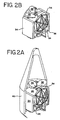
- FIG. 2A shows the spacecraft or satellite body of FIG. 1 in a retracted or stored position on a launch vehicle;
- FIG. 2B shows the spacecraft or satellite body when the spacecraft has left the launch vehicle of FIG. 2A;
- FIG. 3 shows a breakaway perspective view of the spacecraft body when the payload and bus modules of FIG. 1 are separated;
- FIG. 4 shows a top perspective view of the bus module of FIG. 3;
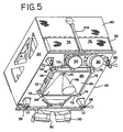
- FIG. 5 shows a bottom perspective view of the bus module of FIG. 4;
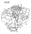
- FIG. 6 shows an exploded view of the bus module of FIGS. 4-5;
- FIG. 7 schematically shows a cross-section of the layout of the electrical components on the bus module of FIG. 3;
- FIG. 8 shows a front view of a shelf to be used with the bus module of FIG. 3;
- FIG. 9 shows a pair of support walls to be used with the bus module of FIGS. 3-6;
- FIG. 10 shows a cross-sectional view of the bus module of FIG. 3;
- FIG. 11 shows an alternative embodiment of an interface for the bus module of FIG. 3;
- FIG. 12 shows an aft end view of the payload module of FIG. 3;
- FIG. 13 shows a cross-sectional view of a side of the payload module of FIG. 3;
- FIG. 14 shows a cross-sectional view of the front of payload module of FIG. 3;
- FIG. 15 shows a perspective view of a second embodiment of a bus module and a payload module according to the present invention;
- FIG. 16A shows a cross-sectional view of the bus module of FIG. 15; and
- FIG. 16B shows a cross-sectional view of the payload module of FIG. 15.
-
- A spacecraft or
satellite 20 employing the present invention is shown in FIGS. 1-16.Satellite 20 has aspacecraft body 22 which includes alower bus module 24 and anupper payload module 26. Attached to the aft end of thelower bus module 24 are a plurality of engines. These engines include a centrally positioned liquid orbital thruster (not shown) and four pairs ofchemical propulsion engines 28 located at the corners of thebus module 24 and two pairs of xenonion propulsion engines 30.Lower bus module 24 contains one ormore fuel tanks 32 and various power and control modules which operate the propulsion system and power thepayload module 26.Bus module 24 further includes a pair ofsolar panels 34 which convert sunlight into electricity which is sent to batteries (not shown) located on thebus module 24.Bus module 24 also has one ormore antennae 36, andreflectors 38 which receive signals from one or more ground stations on Earth which are used to control thesatellite 20.Antennae 36 andreflectors 38 also send signals to the ground stations. -
Payload module 26 is attached to thebus module 24 and contains a variety of electronic equipment which may contain a number of sensors (not shown). The electronic equipment processes information gathered by the sensors and sends the processed information back to the ground stations viaantennae 36 andreflectors 38. The gathered information may concern communications, weather observation, navigational information, etc. - As shown in FIG. 2A,
spacecraft 20 is initially in a stored configuration when loaded on thelaunch vehicle 40. In the stored configuration, all peripheral components, such as thesolar panels 34 and theantennae 36 are folded up to be adjacent to thespacecraft body 22. The peripheral components remain in their folded condition when thespacecraft 20 leaves thelaunch vehicle 40 and moves into a desired orbit. Once in the desired orbit, the peripheral elements are unfolded as shown in FIG. 1. - Supporting the peripheral elements is the
spacecraft body 22 as shown in FIG. 3. As mentioned previously,spacecraft body 22 includes abus module 24 and apayload module 26.Bus module 24, as shown in FIGS. 3-11, includes a base 42 which has anopening 44 to allow a mainorbital thruster nozzle 46 to be inserted therethrough.Base 42 has aperimeter 48 with foursides 50 which define a polygon, such as a rectangle or a square. Preferably,perimeter 48 has a length of approximately 175" and a width of approximately 100". Attached to the base 42 are fourside walls Side walls side walls base 42.Side walls perimeter 48 and are attached toside walls side walls exterior panels side walls exterior panels side panels exterior panels Panels base 42 is accomplished in a well known manner, such as mechanical fastening or bonding. Mechanical fastening may include using threaded bolts and nuts. The side walls andexterior panels - A top panel or
interface 64 is then attached, via a mechanical fastener, to all four side walls so thatbase 42,side walls interface 64 enclose an interior volume of space. Within the interior volume of space, one ormore fuel tanks 32 are located. Preferably, four of thefuel tanks 32 are in fluid communication with a main orbital engine (not shown) attached to the base 42 so that fuel is fed to the engine. The main orbital engine propels thesatellite 20 into the proper orbit after thesatellite 20 has left thelaunch vehicle 40. The main orbital thruster is supported on a pyramid-like plume shield 66 which has fourpanels 68 which extend upward throughopening 44.Plume shield 66 is made of a titanium material with a nickel foil and quartz layer located on the exterior. Preferably,plume 66 has a height of approximately and a square bottom base having sides with a length of approximately 45".Panels 68 are welded to each other and form asquare opening 70 through which thenozzle 46 passes.Panels 68 are also attached to corresponding metal bars 72 which are attached to the underside ofbase 42. Metal bars 72 are attached tobase 42 and to fourfittings 74 by mechanical fasteners.Fittings 74 are likewise mechanically attached to thecorner slots 76 ofopening 44. - Besides the four
fuel tanks 32 for the main orbital engine, there preferably are separate fuel tanks for each of theion propulsion engines 30 andchemical engines 28. Theinterface 64 is also mechanically attached to theexterior panels base 42,interface 64 andexterior panels side walls fuel tanks 32. Areas II and III containpower system components 78 and attitudecontrol system components 80. Thepower system components 78 and the attitudecontrol system components 80 may be thermally, environmentally, and structurally segregated from each other as well by a hingedshelf 82 which is hingedly attached to aside wall side wall components 80 thereon. - Other embodiments for
shelf 82 are possible. First,shelf 82 can be hinged to aside wall side walls base 42 when it moves to a deployed position. Second, ashelf 82 positioned parallel tobase 42 may be movable so that the distance from theshelf 82 to base 42 can be varied. As shown in FIG. 8, this is accomplished by attaching theshelf 82 to one of a multiple number of connectors, such asholes 84, which extend from the base 42 tointerface 64. It is understood thatshelf 82 also may be permanently attached towalls exterior panels - As described previously, area I pertains to a volume of space bounded by
base 42,interface 64 andside walls side walls base 42 defines a polygon having two or more diagonals, such as a rectangle or a square. A pair ofsupport walls fittings 74. Thesupport walls side walls support wall bottom piece 92 and atop piece 94 which have slots to receive the halves, as shown in FIG. 9. The bottom andtop pieces support walls fuel tank 32, as shown in FIG. 10. - It should be noted that
base 42,interface 64,side walls support walls shelves 82 andpanels bus module 24 is reduced. As shown by a comparison of FIGS. 1-3 and 4-6, the shape of the apertures can take on various forms. An alternative shape for the apertures ofinterface 64 is shown in FIG. 11. -
Fuel tanks 32 are further secured withinbus module 24 by fourcollars 96 onflexible interface 64 which are attached via bolts to an annular surface of the fuel tank 14. Besides securingfuel tanks 32,interface 64 has a standardized structure designed to receive and attach itself to a standard aft end of asatellite payload module 26. Theinterface 64 has one or more attachment elements orengagement elements 98 which are always arranged thereon in a predetermined and standard pattern so that they receive one or more connection elements from a standardaft end 100 of asatellite payload module 26. Preferably, there is anengagement element 98, such as a standard mechanical interlock, located near each of the four corners of theinterface 64. Similarly, thebus module 28 has an electrical port, such as an electrical pin connector, located at each corner of theinterface 64 and near theengagement elements 98. In addition, the bus module or payload module can contain one or more voltage converters which can assure that the electrical voltages passed from the bus module to the payload module and vice versa are compatible. - The purpose of standardizing the structure of the
interface 64 and the aft end of thepayload module 26 is to allow attachment between a bus module with any payload module. This would allow for the bus and payload modules to be manufactured in different locations and by different corporate entities without worrying whether attachment will be achieved between the modules. - To this end, an embodiment of a
payload module 26 is shown in FIGS. 3 and 12-14 which has an aft end orbase 100 which always has anattachment device 102, such as a standard cone and socket attachment, arranged thereon at a position which corresponds to any one of the predetermined and standard locations oninterface 64 which possess anengagement device 98. Thus, thebus module 24 is attached topayload module 26 by having theattachment device 102 of thepayload module 26 engage with a corresponding engagement element ordevice 98 of thebus module 24. Of course, in order to achieve standardized attachment the number of predetermined and standard locations on the interface must be at least as large as the number ofattachment devices 102 on thepayload module 26. Thepayload module 26 is electrically powered via apower bus 104 attached to both modules. -
Payload module 26 has fourside walls 106 that are attached tobase 100 and which meet at four corners. At each corner are a pair of connectors (not shown) or hinges (not shown) which are hingedly attached to aheat radiator 108 via a pivot member so that theheat radiator 108 is able to rotate about an axis A. -
Base 100 has aperimeter 110 with foursides 112 which define a polygon, such as a rectangle or a square. Preferablyperimeter 110 matches the perimeter ofinterface 64 so that it has a length of approximately 100" and a width of approximately 75".Side walls 106 are attached to and positioned substantially perpendicular tosides 112. Atop panel 114 is then mechanically attached to all fourside walls 106 so thatbase 100,side walls 106 andtop panel 114 enclose an interior volume of space in which the payload is located. Attachment of the fourside walls 106 tobase 100 is accomplished in a well known manner, such as bolts or bonding. - As shown in FIGS. 13 and 14, a pair of
support walls 116 are attached to base 100 so that they are perpendicular tosides 112 and perpendicular to each other. Attachment is accomplished in a well known manner by way ofbrackets 118 which are attached along the length and width of oppositely facingside walls 106, as shown in FIG. 13.Support walls 116 in conjunction withside walls 106,base 100 andtop panel 114 form four thermally, environmentally and structurally segregated areas I. II, III, IV. As with thebus module 24, the number of segregated areas can be increased by adding one ormore shelves 118, as shown in FIGS. 13 and 14.Shelves 118 are attached as and can take on the structure of any of the embodiments ofshelf 80 ofbus module 24 as described above. - Like
bus module 24, thebase 100,top panel 114,side walls 106 andshelves 118 are preferably made by a process as described in U.S. Patent No. 5,273,806. Depending on the amount of isolation from the environment and strength requirements, a number of apertures can be formed in the base, top panels, side walls, and support walls, so that the weight of thepayload module 26 is reduced. - Besides the box-like shape of FIGS. 1-14, it is envisioned that the
bus module 24 and/or thepayload module 26 may have a cylindrical shape. As shown in FIGS. 15 and 16A, thebase 120 of such abus module 24 hascircular perimeter 122 which is attached to aninner side wall 124 and anexterior side wall 126. Attached to the inner and outer side walls is acircular interface 128 having the standardized pattern of attachment devices as described above forinterface 64. The side walls define two areas I and II which are structurally and thermally isolated from one another. As before, area I can contain one ormore fuel tanks 32 which are separated from one another by a pair ofsupport walls 130 which lie along the entire length of diameters of the circular perimeter. Preferably the support walls are angled at 90° to each other and are attached as previously described for the embodiment of FIGS. 1-14. - Similarly, a cylindrical pay load module 26 (see FIGS. 15 and 16B) would have a circular standard aft end or
base 132 which is structured likebase 100 described above, so as to allow for standardized connection withinterface 128. A pair ofside wall support walls base 132 and a circular top panel 142 in the manner as described above for the payload module of FIGS. 1-14. - In summary, the present invention provides an improved structure for a payload module and a bus module. In particular, the present invention leads to a way of more efficiently constructing satellites by standardizing the attachment between payload and bus modules. The present invention regards a modular design which provides for improved installation of components on a spacecraft by segregating the components thermally, environmentally and structurally.
- The foregoing description is provided to illustrate the invention, and is not to be construed as a limitation. Numerous additions, substitutions and other changes can be made to the invention without departing from its scope as set forth in the appended claims.
Claims (6)
- A space module, comprising:wherein said volume of space is physically divided into a first area and a second area, wherein said first and second areas are thermally and structurally segregated from one another, anda base (42; 100; 120; 132);one or more side walls (52, 54, 60, 62; 106; 124; 134) attached to said base (42; 100; 120; 132); anda top panel (64; 114; 128; 142) attached to said one or more side walls (52, 54, 60, 62; 106; 124; 134), wherein said base (42; 100; 120; 132), said one or more side walls (52, 54, 60, 62; 106; 124; 134) and said top panel (64; 114; 128; 142) enclose an interior volume of space;
wherein a plurality of side walls (56, 58) attached to said base (42) is provided so that a cross-section of said side walls (56, 58) taken parallel to said base (42) defines a polygon having two or more diagonals, characterized by
a support wall (86) lying within said interior volume of space and along the entire length of one of said diagonals and attached to said base (42) and said top panel (64). - The space module of claim 1, characterized in that said base (122; 132) defines a circular perimeter (122);
a support wall (130; 138) lying within said interior volume of space and along the entire length of a diameter of said circular perimeter (122) and attached to said base (42) and said top panel (64). - The space module of claim 1 or 2, characterized by a second support wall (88; 130; 138) lying within said inferior volume of space and along the entire length of a diagonal or diameter of said base (42; 122; 132) and attached to said base (42; 122; 132) and said top panel (64; 128; 142).
- The space module of any of claims 1, 2 or 3, characterized in that said top panel (64) has a structure designed to receive and attach itself to a standardized section (100) of a satellite payload module (26).
- The space module of claim 4, characterized in that said top panel (64) has a plurality of engagement elements (98) which are arranged in a pattern so that they receive one or more connection elements (102) from said standardized section (100) of said satellite payload module (26).
- The space module of claim 4 or 5, characterized by:an engine (28, 30) attached to said base (42);a fuel tank (32) containing a fuel and located within said interior volume of space, wherein said fuel tank (32) is in fluid communication with said engine so that said fuel is fed to said engine (28, 30);said top panel (64) having a collar (96) to engage an annular surface of said fuel tank (32).
Applications Claiming Priority (2)
| Application Number | Priority Date | Filing Date | Title |
|---|---|---|---|
| US08/577,441 US5755406A (en) | 1995-12-22 | 1995-12-22 | Modular, independent subsystem design satellite bus and variable communication payload configurations and missions |
| US577441 | 1995-12-22 |
Publications (3)
| Publication Number | Publication Date |
|---|---|
| EP0780294A2 EP0780294A2 (en) | 1997-06-25 |
| EP0780294A3 EP0780294A3 (en) | 1999-03-10 |
| EP0780294B1 true EP0780294B1 (en) | 2003-05-02 |
Family
ID=24308752
Family Applications (1)
| Application Number | Title | Priority Date | Filing Date |
|---|---|---|---|
| EP96120411A Expired - Lifetime EP0780294B1 (en) | 1995-12-22 | 1996-12-18 | Space module |
Country Status (3)
| Country | Link |
|---|---|
| US (1) | US5755406A (en) |
| EP (1) | EP0780294B1 (en) |
| DE (1) | DE69627796T2 (en) |
Families Citing this family (52)
| Publication number | Priority date | Publication date | Assignee | Title |
|---|---|---|---|---|
| US5961076A (en) * | 1996-12-20 | 1999-10-05 | Trw Inc. | Modular spacecraft development process |
| US5904317A (en) * | 1996-12-20 | 1999-05-18 | Trw Inc. | Method for adjusting stiffness and acoustic properties of an externally mountable spacecraft equipment module |
| US5931418A (en) * | 1996-12-20 | 1999-08-03 | Trw Inc. | Functionally independent spacecraft module |
| US5950965A (en) * | 1997-07-17 | 1999-09-14 | Lockheed Martin Corporation | Split shell spacecraft |
| US6131857A (en) * | 1998-10-30 | 2000-10-17 | Hebert; Barry Francis | Miniature spacecraft |
| US6206327B1 (en) | 1999-03-31 | 2001-03-27 | Lockheed Martin Corporation | Modular spacecraft bus |
| US6293499B1 (en) * | 1999-11-16 | 2001-09-25 | The Boeing Company | Modular, producible, testable and serviceable spacecraft design |
| US7028953B2 (en) * | 2001-11-11 | 2006-04-18 | Space Systems/Loral | Two-sided deployable thermal radiator system and method |
| US6945498B2 (en) | 2002-10-15 | 2005-09-20 | Kistler Aerospace Corporation | Commercial experiment system in orbit |
| US7302364B2 (en) * | 2004-07-30 | 2007-11-27 | The Boeing Company | Methods and systems for advanced spaceport information management |
| US20060185277A1 (en) * | 2004-08-16 | 2006-08-24 | Utah State University | Modular platform system |
| US20070029446A1 (en) * | 2005-05-02 | 2007-02-08 | Mosher Todd J | Modular platform architecture for satellites |
| US20070040702A1 (en) * | 2005-05-02 | 2007-02-22 | Mosher Todd J | Method for creating highly integrated satellite systems |
| US8905357B1 (en) * | 2009-10-02 | 2014-12-09 | MMA Design, LLC | Thin membrane structure |
| KR101145953B1 (en) | 2009-12-24 | 2012-05-15 | 한국항공우주연구원 | Opening and holding apparatus of satellite body pannel |
| FR2959490B1 (en) * | 2010-04-28 | 2012-07-13 | Astrium Sas | SATELLITE HAVING A SIMPLIFIED, ALLEGE AND ECONOMIC STRUCTURE AND ITS IMPLEMENTING METHOD |
| US9550584B1 (en) | 2010-09-30 | 2017-01-24 | MMA Design, LLC | Deployable thin membrane apparatus |
| US8448902B2 (en) * | 2011-02-11 | 2013-05-28 | Space Systems/Loral LLC | Satellite having multiple aspect ratios |
| US9004409B1 (en) | 2011-08-23 | 2015-04-14 | Space Systems/Loral, Llc | Extendable antenna reflector deployment techniques |
| US9248922B1 (en) | 2011-08-23 | 2016-02-02 | Space Systems/Loral, Llc | Reflector deployment techniques for satellites |
| CN102616385B (en) * | 2012-04-11 | 2015-01-14 | 深圳航天东方红海特卫星有限公司 | Truss-type satellite structure with central capsule |
| US8915472B2 (en) * | 2012-05-11 | 2014-12-23 | The Boeing Company | Multiple space vehicle launch system |
| US9180984B2 (en) | 2012-05-11 | 2015-11-10 | The Boeing Company | Methods and apparatus for performing propulsion operations using electric propulsion systems |
| FR3013684B1 (en) * | 2013-11-22 | 2017-10-13 | Astrium Sas | SATELLITE CARRIER STRUCTURE COMPRISING A DAMPING LINK DEVICE |
| FR3023264B1 (en) * | 2014-07-04 | 2017-11-24 | Thales Sa | SATELLITE A MASTER VARIABLE COUPLE |
| US9698492B2 (en) * | 2015-01-28 | 2017-07-04 | Northrop Grumman Systems Corporation | Low-cost diplexed multiple beam integrated antenna system for LEO satellite constellation |
| US20160288931A1 (en) * | 2015-03-31 | 2016-10-06 | Worldvu Satellites Limited | Satellite frame and method of making a satellite |
| EP3095714A1 (en) * | 2015-05-19 | 2016-11-23 | Airbus DS GmbH | Modular satellite |
| CN105416611B (en) * | 2015-11-30 | 2017-06-27 | 中国空间技术研究院 | A plate-type satellite device suitable for high-orbit satellites |
| RU2617162C1 (en) * | 2016-01-18 | 2017-04-21 | Федеральное государственное унитарное предприятие "Научно-производственное объединение им. С.А. Лавочкина" | Spacecraft, its payload module and service system module |
| WO2017134689A2 (en) * | 2016-02-06 | 2017-08-10 | Axiom Research Labs Private Limited | Adaptable satellite bus |
| WO2018061226A1 (en) * | 2016-09-29 | 2018-04-05 | 三菱電機株式会社 | Pointing mechanism |
| US11072441B2 (en) | 2017-03-03 | 2021-07-27 | Northrop Grumman Systems Corporation | Stackable spacecraft |
| CN107244427B (en) * | 2017-05-31 | 2019-05-24 | 北京空间飞行器总体设计部 | A kind of main structure allosteric type satellite platform |
| US10745152B2 (en) * | 2017-06-01 | 2020-08-18 | Swarm Technologies, Inc. | Attitude stabilization and orbital distribution for small satellites |
| CN107352046B (en) * | 2017-06-06 | 2019-09-06 | 北京空间飞行器总体设计部 | A satellite payload structure |
| US10669048B1 (en) * | 2017-06-15 | 2020-06-02 | United Launch Alliance, L.L.C. | Mechanism for increasing jettison clearance |
| US10981679B2 (en) | 2017-08-04 | 2021-04-20 | Rocket Lab Usa, Inc. | Satellite deployer door release mechanism |
| KR102002306B1 (en) * | 2018-01-08 | 2019-07-22 | 주식회사 버츄얼랩 | Cubesat Space Deployer |
| CN108438253A (en) * | 2018-03-06 | 2018-08-24 | 航天东方红卫星有限公司 | A kind of microsatellite structure suitable for optics load |
| US11242161B1 (en) * | 2018-05-24 | 2022-02-08 | David Michael White | Cube-shaped primary structure module |
| US11873119B1 (en) | 2018-08-03 | 2024-01-16 | The United States Of America, As Represented By The Secretary Of The Army | Fast, swappable modular tray and rack structure |
| US11827389B2 (en) * | 2020-05-18 | 2023-11-28 | The Boeing Company | Additively manufactured satellite |
| US11802606B2 (en) | 2020-05-18 | 2023-10-31 | The Boeing Company | Planate dynamic isolator |
| CN112319851B (en) * | 2020-10-20 | 2022-12-09 | 北京空间飞行器总体设计部 | A large box-type communication cabin structure |
| CA3140350A1 (en) | 2020-12-17 | 2022-06-17 | The Boeing Company | Satellite thermal enclosure |
| CA3140352A1 (en) | 2020-12-17 | 2022-06-17 | The Boeing Company | Stacked satellite assemblies and related methods |
| CN113911396A (en) * | 2021-09-30 | 2022-01-11 | 北京空间飞行器总体设计部 | Secondary modular structure with adjustable connection and mounting and dismounting method thereof |
| CA3253137A1 (en) * | 2022-02-25 | 2023-08-31 | Network Access Associates Limited | Space vehicle and method for manufacture thereof |
| US12358656B2 (en) * | 2022-05-31 | 2025-07-15 | Sidus Space, Inc. | System for a modular satellite testing platform |
| US20240262535A1 (en) * | 2023-01-13 | 2024-08-08 | True Anomaly, Inc. | Modular Spacecraft Bus System and Associated Methods |
| CN119796524A (en) * | 2024-12-03 | 2025-04-11 | 星瀚时空(深圳)航天智能科技有限公司 | A satellite assembly method |
Family Cites Families (12)
| Publication number | Priority date | Publication date | Assignee | Title |
|---|---|---|---|---|
| US4009851A (en) * | 1974-12-23 | 1977-03-01 | Rca Corporation | Spacecraft structure |
| US4324375A (en) * | 1979-12-26 | 1982-04-13 | General Dynamics Corporation | Heat sink/fluid-to-fluid mechanical coupling of spacecraft coolant systems |
| DE3376549D1 (en) * | 1983-09-03 | 1988-06-16 | Erno Raumfahrttechnik Gmbh | Satellite system with variable configuration |
| GB8526723D0 (en) * | 1985-10-30 | 1985-12-04 | Rca Corp | Spacecraft structure |
| US4767084A (en) * | 1986-09-18 | 1988-08-30 | Ford Aerospace & Communications Corporation | Autonomous stationkeeping for three-axis stabilized spacecraft |
| US5372183A (en) * | 1991-08-22 | 1994-12-13 | Strickberger; Harold P. | Thermal control arrangements for a geosynchronous spacecraft |
| US5273806A (en) | 1991-10-03 | 1993-12-28 | Lockshaw James J | Structural element with interlocking ribbing |
| US5314146A (en) * | 1992-03-13 | 1994-05-24 | Spectrum Astro, Inc. | Multi-mission spacecraft bus having space frame structural design |
| US5349532A (en) * | 1992-04-28 | 1994-09-20 | Space Systems/Loral | Spacecraft attitude control and momentum unloading using gimballed and throttled thrusters |
| US5344104A (en) * | 1992-09-21 | 1994-09-06 | General Electric Co. | Low cost, selectable configuration spacecraft |
| US5443231A (en) * | 1993-11-17 | 1995-08-22 | Hughes Aircraft Company | Method and apparatus for a satellite station keeping |
| US5474262A (en) * | 1994-02-08 | 1995-12-12 | Fairchild Space And Defense Corporation | Spacecraft structure and method |
-
1995
- 1995-12-22 US US08/577,441 patent/US5755406A/en not_active Expired - Lifetime
-
1996
- 1996-12-18 DE DE69627796T patent/DE69627796T2/en not_active Expired - Lifetime
- 1996-12-18 EP EP96120411A patent/EP0780294B1/en not_active Expired - Lifetime
Also Published As
| Publication number | Publication date |
|---|---|
| US5755406A (en) | 1998-05-26 |
| EP0780294A3 (en) | 1999-03-10 |
| DE69627796D1 (en) | 2003-06-05 |
| DE69627796T2 (en) | 2004-03-18 |
| EP0780294A2 (en) | 1997-06-25 |
Similar Documents
| Publication | Publication Date | Title |
|---|---|---|
| US5755406A (en) | Modular, independent subsystem design satellite bus and variable communication payload configurations and missions | |
| US5314146A (en) | Multi-mission spacecraft bus having space frame structural design | |
| US5979833A (en) | Modular spacecraft architecture | |
| EP3569508B1 (en) | Stackable pancake satellite | |
| EP0780295B1 (en) | Modular payload arrangement | |
| EP4015398B1 (en) | Stacked satellite assemblies and related methods | |
| US5310141A (en) | Battery thermal control arrangement | |
| US4834325A (en) | Modular spacecraft system | |
| EP3024732B1 (en) | Side-by-side dual-launch arrangement with improved payload compatibility | |
| US5961076A (en) | Modular spacecraft development process | |
| US4384692A (en) | Satellite system configuration | |
| US6131857A (en) | Miniature spacecraft | |
| CN102009746A (en) | Octagonal battery-equipped array upright post micro satellite configuration | |
| US5931418A (en) | Functionally independent spacecraft module | |
| US5337980A (en) | Spacecraft-to-launch-vehicle transition | |
| US5950965A (en) | Split shell spacecraft | |
| JP5414181B2 (en) | Spacecraft adapter with embedded resources and method of forming the same | |
| US11053029B1 (en) | Modular high thermal capacity spacecraft | |
| US5717576A (en) | Device and method for protecting electronic units in a satellite from electrical disturbance | |
| US12415624B2 (en) | Thermally efficient bus housing | |
| EP4686657A1 (en) | Spacecraft platform structure | |
| Zhicheng et al. | Nigcomsat-1, the first export commercial Communications satellite of china |
Legal Events
| Date | Code | Title | Description |
|---|---|---|---|
| PUAI | Public reference made under article 153(3) epc to a published international application that has entered the european phase |
Free format text: ORIGINAL CODE: 0009012 |
|
| AK | Designated contracting states |
Kind code of ref document: A2 Designated state(s): DE FR GB |
|
| RAP1 | Party data changed (applicant data changed or rights of an application transferred) |
Owner name: HUGHES ELECTRONICS CORPORATION |
|
| PUAL | Search report despatched |
Free format text: ORIGINAL CODE: 0009013 |
|
| AK | Designated contracting states |
Kind code of ref document: A3 Designated state(s): DE FR GB |
|
| 17P | Request for examination filed |
Effective date: 19990728 |
|
| GRAH | Despatch of communication of intention to grant a patent |
Free format text: ORIGINAL CODE: EPIDOS IGRA |
|
| RTI1 | Title (correction) |
Free format text: SPACE MODULE |
|
| GRAH | Despatch of communication of intention to grant a patent |
Free format text: ORIGINAL CODE: EPIDOS IGRA |
|
| GRAA | (expected) grant |
Free format text: ORIGINAL CODE: 0009210 |
|
| AK | Designated contracting states |
Designated state(s): DE FR GB |
|
| REG | Reference to a national code |
Ref country code: GB Ref legal event code: FG4D |
|
| REF | Corresponds to: |
Ref document number: 69627796 Country of ref document: DE Date of ref document: 20030605 Kind code of ref document: P |
|
| ET | Fr: translation filed | ||
| PLBE | No opposition filed within time limit |
Free format text: ORIGINAL CODE: 0009261 |
|
| STAA | Information on the status of an ep patent application or granted ep patent |
Free format text: STATUS: NO OPPOSITION FILED WITHIN TIME LIMIT |
|
| 26N | No opposition filed |
Effective date: 20040203 |
|
| REG | Reference to a national code |
Ref country code: FR Ref legal event code: PLFP Year of fee payment: 20 |
|
| PGFP | Annual fee paid to national office [announced via postgrant information from national office to epo] |
Ref country code: GB Payment date: 20151229 Year of fee payment: 20 |
|
| PGFP | Annual fee paid to national office [announced via postgrant information from national office to epo] |
Ref country code: FR Payment date: 20151217 Year of fee payment: 20 |
|
| PGFP | Annual fee paid to national office [announced via postgrant information from national office to epo] |
Ref country code: DE Payment date: 20151229 Year of fee payment: 20 |
|
| REG | Reference to a national code |
Ref country code: DE Ref legal event code: R071 Ref document number: 69627796 Country of ref document: DE |
|
| REG | Reference to a national code |
Ref country code: GB Ref legal event code: PE20 Expiry date: 20161217 |
|
| PG25 | Lapsed in a contracting state [announced via postgrant information from national office to epo] |
Ref country code: GB Free format text: LAPSE BECAUSE OF EXPIRATION OF PROTECTION Effective date: 20161217 |