EP0780231B1 - Continuous ink jet printer print head - Google Patents
Continuous ink jet printer print head Download PDFInfo
- Publication number
- EP0780231B1 EP0780231B1 EP96309228A EP96309228A EP0780231B1 EP 0780231 B1 EP0780231 B1 EP 0780231B1 EP 96309228 A EP96309228 A EP 96309228A EP 96309228 A EP96309228 A EP 96309228A EP 0780231 B1 EP0780231 B1 EP 0780231B1
- Authority
- EP
- European Patent Office
- Prior art keywords
- gutter
- droplets
- print head
- ink
- charge electrode
- Prior art date
- Legal status (The legal status is an assumption and is not a legal conclusion. Google has not performed a legal analysis and makes no representation as to the accuracy of the status listed.)
- Expired - Lifetime
Links
- 238000000034 method Methods 0.000 claims description 5
- 239000000758 substrate Substances 0.000 description 5
- 230000003213 activating effect Effects 0.000 description 2
- 230000005684 electric field Effects 0.000 description 2
- 238000005259 measurement Methods 0.000 description 1
Images

Classifications
-
- B—PERFORMING OPERATIONS; TRANSPORTING
- B41—PRINTING; LINING MACHINES; TYPEWRITERS; STAMPS
- B41J—TYPEWRITERS; SELECTIVE PRINTING MECHANISMS, i.e. MECHANISMS PRINTING OTHERWISE THAN FROM A FORME; CORRECTION OF TYPOGRAPHICAL ERRORS
- B41J2/00—Typewriters or selective printing mechanisms characterised by the printing or marking process for which they are designed
- B41J2/005—Typewriters or selective printing mechanisms characterised by the printing or marking process for which they are designed characterised by bringing liquid or particles selectively into contact with a printing material
- B41J2/01—Ink jet
- B41J2/07—Ink jet characterised by jet control
- B41J2/075—Ink jet characterised by jet control for many-valued deflection
- B41J2/08—Ink jet characterised by jet control for many-valued deflection charge-control type
- B41J2/085—Charge means, e.g. electrodes
-
- B—PERFORMING OPERATIONS; TRANSPORTING
- B41—PRINTING; LINING MACHINES; TYPEWRITERS; STAMPS
- B41J—TYPEWRITERS; SELECTIVE PRINTING MECHANISMS, i.e. MECHANISMS PRINTING OTHERWISE THAN FROM A FORME; CORRECTION OF TYPOGRAPHICAL ERRORS
- B41J2/00—Typewriters or selective printing mechanisms characterised by the printing or marking process for which they are designed
- B41J2/005—Typewriters or selective printing mechanisms characterised by the printing or marking process for which they are designed characterised by bringing liquid or particles selectively into contact with a printing material
- B41J2/01—Ink jet
- B41J2/015—Ink jet characterised by the jet generation process
- B41J2/02—Ink jet characterised by the jet generation process generating a continuous ink jet
- B41J2/025—Ink jet characterised by the jet generation process generating a continuous ink jet by vibration
-
- B—PERFORMING OPERATIONS; TRANSPORTING
- B41—PRINTING; LINING MACHINES; TYPEWRITERS; STAMPS
- B41J—TYPEWRITERS; SELECTIVE PRINTING MECHANISMS, i.e. MECHANISMS PRINTING OTHERWISE THAN FROM A FORME; CORRECTION OF TYPOGRAPHICAL ERRORS
- B41J2/00—Typewriters or selective printing mechanisms characterised by the printing or marking process for which they are designed
- B41J2/005—Typewriters or selective printing mechanisms characterised by the printing or marking process for which they are designed characterised by bringing liquid or particles selectively into contact with a printing material
- B41J2/01—Ink jet
- B41J2/17—Ink jet characterised by ink handling
- B41J2/18—Ink recirculation systems
- B41J2/185—Ink-collectors; Ink-catchers
-
- B—PERFORMING OPERATIONS; TRANSPORTING
- B41—PRINTING; LINING MACHINES; TYPEWRITERS; STAMPS
- B41J—TYPEWRITERS; SELECTIVE PRINTING MECHANISMS, i.e. MECHANISMS PRINTING OTHERWISE THAN FROM A FORME; CORRECTION OF TYPOGRAPHICAL ERRORS
- B41J2/00—Typewriters or selective printing mechanisms characterised by the printing or marking process for which they are designed
- B41J2/005—Typewriters or selective printing mechanisms characterised by the printing or marking process for which they are designed characterised by bringing liquid or particles selectively into contact with a printing material
- B41J2/01—Ink jet
- B41J2/17—Ink jet characterised by ink handling
- B41J2/18—Ink recirculation systems
- B41J2/185—Ink-collectors; Ink-catchers
- B41J2002/1853—Ink-collectors; Ink-catchers ink collectors for continuous Inkjet printers, e.g. gutters, mist suction means
Definitions
- the present invention relates to so-called “continuous ink jet printers” of the type in which a stream of ink is emitted under pressure from a nozzle and, by the action of a piezoelectric oscillator, is broken up into droplets which can be selectively charged and then deflected in an electric field onto a substrate.
- Such printers are well known in the art.
- a print head for a continuous ink jet printer having ink supply means for supplying ink under pressure to a nozzle through which ink is emitted in use and broken up into droplets by the action of a piezoelectric oscillator, a charge electrode for applying electrostatic charge to selected droplets in use, a deflection electrode for deflecting the path of charged droplets, and a gutter for collecting droplets not required for printing, wherein the charge electrode and/or the gutter are movable in a direction transverse to the path of the droplets, the movement being controlled by the action of pressurised ink selectively supplied from the ink supply means to a hydraulic actuator or actuators coupled to the charge electrode and/or the gutter.
- the charge electrode may be withdrawn from its normal operating position laterally to avoid being spattered by ink droplets.
- the gutter may also be able to be positioned so that all droplets issuing from the nozzle during the start-up phase, whether charged or not, pass into the gutter and do not pass to the underlying substrate.
- the charge electrode is mounted for movement with a deflection electrode.
- the invention also includes a method of operating a print head according to the present invention wherein the charge electrode is moved laterally out of its normal operating position so that it is withdrawn from proximity to the stream of droplets.
- a further method using a print head according to the invention involves moving the gutter laterally to a position in which all droplets enter the gutter during start-up.
- the print head has an electronics sub-system 1 by means of which are controlled the piezoelectric oscillator in a droplet generator 2, together with the application of appropriate voltages to charge electrodes 3 and deflection electrodes 4,4' and by means of which appropriate signals are given to valves (not shown) in the printer cabinet (not shown) controlling the flow of ink to the droplet generator 2.
- the droplet generator 2 has a nozzle plate 5 with a plurality of closely spaced nozzles arranged in a row (normal to the plane of the drawing) and from which issue, in use, streams of ink 20 (the plane of which is thus normal to the plane of the figure) which, under the action of the piezoelectric oscillator, break up into individual droplets for printing purposes.
- the droplets pass individual charge electrodes 3 (seen end-on in the drawing), also arranged in a row in the same direction, where they are selectively charged and then passed between the pair of deflection electrodes 4, 4' which establish, in use, an electric field by means of which charged droplets are deflected from their straight-line path into a gutter 6. In the start-up position of the gutter 6 (not shown in the drawing) even uncharged droplets (which in the present case are used for printing) pass into the gutter.
- ink is supplied from a supply means 14 to an ink chamber (not shown) within the drop generator 2 above the nozzle plate 5, via a feed line 7 and is also supplied to first 8 and second 9 hydraulic actuators, via lines 8'' and 9'', through the action of the appropriate valves (not shown) mounted in the printer cabinet (not shown).
- the first actuator 8 which is supported on a bracket 10, has a piston 8' which is arranged to bear against one end of a lever arm 11 at the other end of which is mounted the gutter 6.
- the second actuator 9 is also mounted on the bracket 10 and has a piston 9' which engages, via a pair of links 12, 12', a flexible support bracket 13 for the charge electrodes 3 and the deflection electrode 4.
- the gutter 6 By selectively operating the valves which control the supply of pressurised ink to the first and second actuators 8, 9 respectively, the gutter 6 can be withdrawn from the "catch-all" position into the position shown in the drawing which is an operating position in which only charged droplets are deflected into the gutter, non-charged droplets being allowed to pass onto the substrate for printing, and the charge electrodes 3 and deflection electrode 4 can be moved rightwards from the position shown in the drawing, to a position in which the charge electrodes 3 are closely adjacent the streams of droplets 20 and the deflection electrode 4 is in the appropriate position relative to the other deflection electrode 4'.
- This position is defined by an adjustable stop screw 15 which bears against an abutment 16 on the side of the nozzle plate 5.
- the start/stop sequence described below uses four solenoid valves; jet, bleed, charge electrode actuator and gutter actuator, none of which are shown in the drawing.
- the jet solenoid valve (aka the feed solenoid) is a two-way solenoid valve which is mounted in the print head and controls the flow of ink to the drop generator 2 through the feed line 7.
- the bleed solenoid is a similar type of valve to the jet/feed solenoid valve and is also mounted in the print head and controls flow through a bleed line (not shown). When open, it allows a flow of ink through the bleed line from the drop generator 2 primarily to remove ingressed air during start up. During shut down it is also opened to cause a very quick jet shut off by de-pressurising the drop generator. This is helped by connecting the bleed to vacuum source (not shown) which is used to draw ink from the gutter 6.
- the charge electrode actuator valve is a three-port solenoid valve mounted in the ink cabinet. When activated ink is supplied to the actuator 9 so that the charge electrode 3 moves into the print position. When de-activated, the charge electrode 3 returns to its 'safe', jet start position (as shown in the drawing).
- the gutter actuator valve is similar to the charge electrode actuator valve and is mounted in the cabinet. When activated, it causes ink to flow to the gutter actuator 8 which moves the gutter 6 into the print position (as shown). When deactivated the gutter 6 is in the "catch all" position needed for jet start up and shut down, rightwards of the position shown in the drawing.
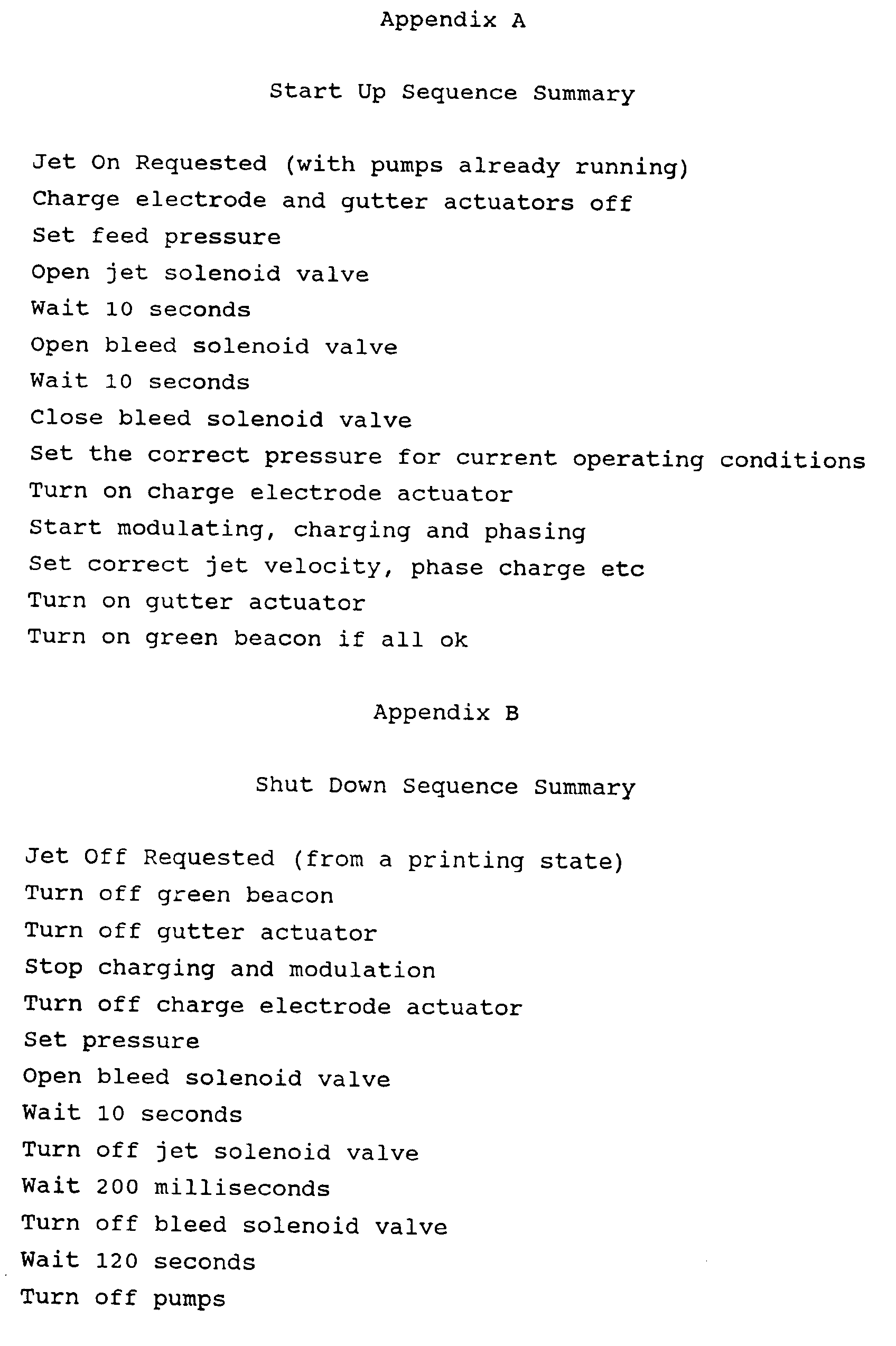
- the start up sequence is as follows:
- the jet solenoid valve opens.
- the jets start (which causes the pressure to drop).
- the actuators 8,9 require a certain pressure to operate so if the pressure drops below this value the sequence must wait until the pressure reaches this value.
- the bleed valve opens for ten seconds which causes another drop in the pressure. Again, the pressure control system can ignore this drop, so long as it is above the minimum pressure.
- the pressure control system can establish the pressure required for the current operating parameters. Once the correct pressure is established the charge electrodes 3 are moved rightwards into the operating position by activating the charge electrode solenoid valve. At this point, modulation, phasing, jet velocity measurement and charging can start. Once this has been completed the jets should be being deflected into the back of the gutter 6. At this stage it is safe to move the gutter to the print position shown, by activating the gutter actuator 8. At this stage printing can start.
- the jet stop sequence begins with the gutter actuator 8 closing so that the gutter 6 returns to the catch all position. It is then safe to stop charging, phasing and modulation and move the charge electrodes 3 to the 'safe' position by de-activating the charge electrode actuator 9. Like the jet start sequence, the jet stop sequence begins with setting the pressure. Once this has been established the bleed solenoid valve opens. After ten seconds, the jet solenoid valve closes shortly followed by the bleed solenoid valve.
- the pressure control system need not try to maintain the generating pressure and pressure control faults should be ignored. After the jets have been turned off, the pumps should continue to run, to clear the gutter, before being turned off.
Landscapes
- Particle Formation And Scattering Control In Inkjet Printers (AREA)
- Ink Jet (AREA)
Description
- The present invention relates to so-called "continuous ink jet printers" of the type in which a stream of ink is emitted under pressure from a nozzle and, by the action of a piezoelectric oscillator, is broken up into droplets which can be selectively charged and then deflected in an electric field onto a substrate. Such printers are well known in the art.
- Although such printers have been available for many years, problems arise still during the start-up of such a printer. Frequently, the stream of ink issuing from the nozzle is unstable at start-up and this can cause ink to impinge on components of the print head undesirably. In particular, ink impinging on the electrode used to charge the droplets can cause unstable conditions to persist and charging to be inaccurate with the result that droplets are not correctly placed on the substrate.
- Also during start-up, there is a need to ensure that guard droplets and non-printable droplets pass correctly into the gutter which is provided for their collection. Additionally, when the printer is of the type in which uncharged droplets are "printed" and charged droplets are either guard drops or non-printable drops, when the printer is first switched on and the stream of ink starts to issue from the nozzle, it is desirable to avoid wastage of ink or the unnecessary application of ink to part of a substrate which will then not be to be used (see US-A-4305079).
- According to the present invention, there is provided a print head for a continuous ink jet printer, the print head having ink supply means for supplying ink under pressure to a nozzle through which ink is emitted in use and broken up into droplets by the action of a piezoelectric oscillator, a charge electrode for applying electrostatic charge to selected droplets in use, a deflection electrode for deflecting the path of charged droplets, and a gutter for collecting droplets not required for printing, wherein the charge electrode and/or the gutter are movable in a direction transverse to the path of the droplets, the movement being controlled by the action of pressurised ink selectively supplied from the ink supply means to a hydraulic actuator or actuators coupled to the charge electrode and/or the gutter.
- Thus, during start-up, the charge electrode may be withdrawn from its normal operating position laterally to avoid being spattered by ink droplets. The gutter may also be able to be positioned so that all droplets issuing from the nozzle during the start-up phase, whether charged or not, pass into the gutter and do not pass to the underlying substrate.
- Advantageously, the charge electrode is mounted for movement with a deflection electrode.
- The invention also includes a method of operating a print head according to the present invention wherein the charge electrode is moved laterally out of its normal operating position so that it is withdrawn from proximity to the stream of droplets. A further method using a print head according to the invention involves moving the gutter laterally to a position in which all droplets enter the gutter during start-up.
- One example of a print-head according to the present invention will now be described with reference to the accompanying drawing which illustrates the print head in side view.
- The print head has an electronics sub-system 1 by means of which are controlled the piezoelectric oscillator in a
droplet generator 2, together with the application of appropriate voltages to chargeelectrodes 3 anddeflection electrodes 4,4' and by means of which appropriate signals are given to valves (not shown) in the printer cabinet (not shown) controlling the flow of ink to thedroplet generator 2. - The
droplet generator 2 has anozzle plate 5 with a plurality of closely spaced nozzles arranged in a row (normal to the plane of the drawing) and from which issue, in use, streams of ink 20 (the plane of which is thus normal to the plane of the figure) which, under the action of the piezoelectric oscillator, break up into individual droplets for printing purposes. The droplets pass individual charge electrodes 3 (seen end-on in the drawing), also arranged in a row in the same direction, where they are selectively charged and then passed between the pair ofdeflection electrodes 4, 4' which establish, in use, an electric field by means of which charged droplets are deflected from their straight-line path into a gutter 6. In the start-up position of the gutter 6 (not shown in the drawing) even uncharged droplets (which in the present case are used for printing) pass into the gutter. - In use ink is supplied from a supply means 14 to an ink chamber (not shown) within the
drop generator 2 above thenozzle plate 5, via afeed line 7 and is also supplied to first 8 and second 9 hydraulic actuators, via lines 8'' and 9'', through the action of the appropriate valves (not shown) mounted in the printer cabinet (not shown). - The
first actuator 8, which is supported on abracket 10, has a piston 8' which is arranged to bear against one end of alever arm 11 at the other end of which is mounted the gutter 6. Thesecond actuator 9 is also mounted on thebracket 10 and has a piston 9' which engages, via a pair oflinks 12, 12', aflexible support bracket 13 for thecharge electrodes 3 and thedeflection electrode 4. - By selectively operating the valves which control the supply of pressurised ink to the first and
second actuators charge electrodes 3 anddeflection electrode 4 can be moved rightwards from the position shown in the drawing, to a position in which thecharge electrodes 3 are closely adjacent the streams ofdroplets 20 and thedeflection electrode 4 is in the appropriate position relative to the other deflection electrode 4'. This position is defined by anadjustable stop screw 15 which bears against anabutment 16 on the side of thenozzle plate 5. - The start/stop sequence described below uses four solenoid valves; jet, bleed, charge electrode actuator and gutter actuator, none of which are shown in the drawing.
- The jet solenoid valve (aka the feed solenoid) is a two-way solenoid valve which is mounted in the print head and controls the flow of ink to the
drop generator 2 through thefeed line 7. - The bleed solenoid is a similar type of valve to the jet/feed solenoid valve and is also mounted in the print head and controls flow through a bleed line (not shown). When open, it allows a flow of ink through the bleed line from the
drop generator 2 primarily to remove ingressed air during start up. During shut down it is also opened to cause a very quick jet shut off by de-pressurising the drop generator. This is helped by connecting the bleed to vacuum source (not shown) which is used to draw ink from the gutter 6. - The charge electrode actuator valve is a three-port solenoid valve mounted in the ink cabinet. When activated ink is supplied to the
actuator 9 so that thecharge electrode 3 moves into the print position. When de-activated, thecharge electrode 3 returns to its 'safe', jet start position (as shown in the drawing). - The gutter actuator valve is similar to the charge electrode actuator valve and is mounted in the cabinet. When activated, it causes ink to flow to the
gutter actuator 8 which moves the gutter 6 into the print position (as shown). When deactivated the gutter 6 is in the "catch all" position needed for jet start up and shut down, rightwards of the position shown in the drawing. - The start up sequence is as follows:
- With both the gutter and charge electrode actuator solenoid valves off (the gutter in the catch all position, the charge electrode in the jet start position) the feed pressure and gutter pumps start.
- Following a jet start request, the jet solenoid valve opens. The jets start (which causes the pressure to drop). However, the
actuators - After ten seconds, the bleed valve opens for ten seconds which causes another drop in the pressure. Again, the pressure control system can ignore this drop, so long as it is above the minimum pressure.
- Once the bleed valve closes the pressure control system can establish the pressure required for the current operating parameters. Once the correct pressure is established the
charge electrodes 3 are moved rightwards into the operating position by activating the charge electrode solenoid valve. At this point, modulation, phasing, jet velocity measurement and charging can start. Once this has been completed the jets should be being deflected into the back of the gutter 6. At this stage it is safe to move the gutter to the print position shown, by activating thegutter actuator 8. At this stage printing can start. - This sequence is summarised in Appendix A.
- The jet stop sequence begins with the
gutter actuator 8 closing so that the gutter 6 returns to the catch all position. It is then safe to stop charging, phasing and modulation and move thecharge electrodes 3 to the 'safe' position by de-activating thecharge electrode actuator 9. Like the jet start sequence, the jet stop sequence begins with setting the pressure. Once this has been established the bleed solenoid valve opens. After ten seconds, the jet solenoid valve closes shortly followed by the bleed solenoid valve. - As with the start sequence, the pressure control system need not try to maintain the generating pressure and pressure control faults should be ignored. After the jets have been turned off, the pumps should continue to run, to clear the gutter, before being turned off.
- This sequence is summarised in Appendix B.
Claims (7)
- A print head for a continuous ink jet printer having an ink supply means (14) for supplying ink under pressure to the print head, the print head comprising a nozzle (5) through which ink is emitted in use and broken up into droplets by the action of a piezoelectric oscillator, a charge electrode (3) for applying electrostatic charge to selected droplets in use, a deflection electrode (4) for deflecting the path (20) of charged droplets, and a gutter (6) for collecting droplets not required for printing, the charge electrode (3) and/or the gutter (6) being movable in a direction transverse to the path (20) of the droplets, characterised in thatthe movement of the charge electrode (3) and/or the gutter (6) is controlled by the action of pressurised ink selectively supplied from the ink supply means (14) to a hydraulic actuator or actuators (8,9) coupled to the charge electrode (3) and/or the gutter (6).
- A print head according to claim 1, wherein the charge electrode (3) is mounted for movement with a deflection electrode (4).
- A print head according to claim 1 or claim 2, wherein the charge electrode (3) and/or the gutter (6) is/are biased to a non-operating position.
- A print head according to any of claims 1 to 3, wherein the gutter (6) is positionable so that all droplets issuing from the nozzle, whether charged or not, pass into the gutter (6).
- A method of operating a print head according to claim 1, wherein the charge electrode (3) is moved laterally out of its normal operating position so that it is withdrawn from proximity to the stream of droplets (20).
- A method according to claim 5, wherein, during start-up, the charge electrode (3) is withdrawn from its normal operating position laterally to avoid being spattered by ink droplets.
- A method of operating a print head according to claim 1, wherein, during start-up, the gutter (6) is moved laterally to a position in which all droplets enter the gutter (6), whether charged or not.
Applications Claiming Priority (2)
| Application Number | Priority Date | Filing Date | Title |
|---|---|---|---|
| GBGB9525970.1A GB9525970D0 (en) | 1995-12-19 | 1995-12-19 | Continuous ink jet printer |
| GB9525970 | 1995-12-19 |
Publications (2)
| Publication Number | Publication Date |
|---|---|
| EP0780231A1 EP0780231A1 (en) | 1997-06-25 |
| EP0780231B1 true EP0780231B1 (en) | 1999-11-03 |
Family
ID=10785705
Family Applications (1)
| Application Number | Title | Priority Date | Filing Date |
|---|---|---|---|
| EP96309228A Expired - Lifetime EP0780231B1 (en) | 1995-12-19 | 1996-12-18 | Continuous ink jet printer print head |
Country Status (5)
| Country | Link |
|---|---|
| US (2) | US5808642A (en) |
| EP (1) | EP0780231B1 (en) |
| JP (1) | JPH09183227A (en) |
| DE (1) | DE69605013T2 (en) |
| GB (1) | GB9525970D0 (en) |
Families Citing this family (21)
| Publication number | Priority date | Publication date | Assignee | Title |
|---|---|---|---|---|
| US6270204B1 (en) * | 1998-03-13 | 2001-08-07 | Iris Graphics, Inc. | Ink pen assembly |
| JP2000190505A (en) * | 1998-12-25 | 2000-07-11 | Matsushita Electric Ind Co Ltd | Ink jet recording device |
| US6402823B1 (en) | 2000-01-07 | 2002-06-11 | Ferro Corporation | Individual inks and an ink set for use in the color ink jet printing of glazed ceramic tiles and surfaces |
| US6412908B2 (en) * | 2000-05-23 | 2002-07-02 | Silverbrook Research Pty Ltd | Inkjet collimator |
| SG145549A1 (en) * | 2000-05-24 | 2008-09-29 | Silverbrook Res Pty Ltd | A micro-electromechanical fluid ejection device incorporating a movable nozzle structure |
| KR20070042965A (en) * | 2004-06-17 | 2007-04-24 | 비디오제트 테크놀러지즈 인코포레이티드 | System for aligning the charging tunnel of inkjet printer |
| BRPI0810982A2 (en) | 2007-04-27 | 2019-09-24 | Wilson tool int inc | new assemblies and methods for processing workpieces on water hammer presses |
| US20090027460A1 (en) * | 2007-07-23 | 2009-01-29 | Paul Klinker | System for aligning a charge tunnel of an ink jet printer |
| FR2924379B1 (en) * | 2007-11-29 | 2011-04-22 | Imaje Sa | INKJET PRINTING HEAD WITH AUTOMATED CLEANING AT PRINT START |
| FR2955801B1 (en) | 2010-02-01 | 2012-04-13 | Markem Imaje | DEVICE FORMING A CONTINUOUS INK JET PRINTER WITH SOLVENT VAPOR CONCENTRATIONS INSIDE AND AROUND THE DECREASED PUPITRE |
| EP3152061B1 (en) | 2014-06-05 | 2020-10-07 | Videojet Technologies Inc. | Continuous ink jet print head with zero adjustment embedded charging electrode |
| RU2704373C2 (en) | 2014-06-05 | 2019-10-28 | Видеоджет Текнолоджиз Инк. | Self-packing filtration module for jet printing |
| WO2015187926A1 (en) | 2014-06-05 | 2015-12-10 | Videojet Technologies Inc. | An ink buildup sensor arrangement |
| US10906693B2 (en) * | 2014-06-13 | 2021-02-02 | Rakuten, Inc. | Corrugated fiberboard box |
| USD755863S1 (en) | 2014-08-01 | 2016-05-10 | Wilson Tool International Inc. | Tool |
| USD744554S1 (en) | 2014-08-01 | 2015-12-01 | Wilson Tool International Inc. | Tool |
| USD751500S1 (en) | 2014-08-01 | 2016-03-15 | Wilson Tool International Inc. | Battery cartridge |
| US9507332B2 (en) | 2014-08-01 | 2016-11-29 | Wilson Tool International Inc. | Multi-use active tool assembly |
| USD756452S1 (en) | 2014-08-01 | 2016-05-17 | Wilson Tool International Inc. | Cartridge |
| FR3082778A1 (en) * | 2018-06-21 | 2019-12-27 | Dover Europe Sarl | PRINTHEAD OF AN INK JET PRINTER WITH 2 RECOVERY GUTTERS, INCLUDING A MOBILE |
| GB2625357A (en) * | 2022-12-15 | 2024-06-19 | Videojet Technologies Inc | Charge electrode |
Family Cites Families (7)
| Publication number | Priority date | Publication date | Assignee | Title |
|---|---|---|---|---|
| US4277790A (en) * | 1979-12-26 | 1981-07-07 | International Business Machines Corporation | Field replaceable modules for ink jet head assembly |
| US4347520A (en) * | 1979-09-12 | 1982-08-31 | The Mead Corporation | Ink jet printer |
| US4305079A (en) * | 1979-09-24 | 1981-12-08 | International Business Machines Corp. | Movable ink jet gutter |
| US4413265A (en) * | 1982-03-08 | 1983-11-01 | The Mead Corporation | Ink jet printer |
| US4573057A (en) * | 1985-03-04 | 1986-02-25 | Burlington Industries, Inc. | Continuous ink jet auxiliary droplet catcher and method |
| FR2681010B1 (en) * | 1991-09-10 | 1995-02-17 | Imaje | MULTIJET PRINTING MODULE AND PRINTING APPARATUS HAVING MULTIPLE MODULES. |
| GB9301624D0 (en) * | 1993-01-27 | 1993-03-17 | Domino Printing Sciences Plc | Ink jet printer |
-
1995
- 1995-12-19 GB GBGB9525970.1A patent/GB9525970D0/en active Pending
-
1996
- 1996-12-05 US US08/760,486 patent/US5808642A/en not_active Expired - Lifetime
- 1996-12-18 EP EP96309228A patent/EP0780231B1/en not_active Expired - Lifetime
- 1996-12-18 DE DE69605013T patent/DE69605013T2/en not_active Expired - Lifetime
- 1996-12-19 JP JP8354447A patent/JPH09183227A/en active Pending
-
1998
- 1998-04-06 US US09/056,026 patent/US5943077A/en not_active Expired - Lifetime
Also Published As
| Publication number | Publication date |
|---|---|
| EP0780231A1 (en) | 1997-06-25 |
| US5943077A (en) | 1999-08-24 |
| GB9525970D0 (en) | 1996-02-21 |
| DE69605013T2 (en) | 2000-02-24 |
| DE69605013D1 (en) | 1999-12-09 |
| JPH09183227A (en) | 1997-07-15 |
| US5808642A (en) | 1998-09-15 |
Similar Documents
| Publication | Publication Date | Title |
|---|---|---|
| US5808642A (en) | Continuous ink jet printer print head | |
| US6505921B2 (en) | Ink jet apparatus having amplified asymmetric heating drop deflection | |
| JP4787304B2 (en) | Image printing apparatus and method for separating ink droplets | |
| EP1243426B1 (en) | A continuous ink-jet printhead for modifying ink drop placement | |
| US8226215B2 (en) | Jetting module install mechanism | |
| US6899410B2 (en) | Continuous ink-jet printing apparatus with integral cleaning | |
| US20110109698A1 (en) | Liquid drop dispenser with movable deflector | |
| JP2002225280A (en) | Device and method for printing image | |
| EP0911168A3 (en) | Continuous ink jet printer with asymmetric heating drop deflection | |
| US8091983B2 (en) | Jet directionality control using printhead nozzle | |
| EP2013024A1 (en) | Deflected drop liquid pattern deposition | |
| US6474781B1 (en) | Continuous ink-jet printing method and apparatus with nozzle clusters | |
| EP0026836B1 (en) | Ink jet printer | |
| US7967423B2 (en) | Pressure modulation cleaning of jetting module nozzles | |
| US20050231558A1 (en) | Apparatus and method of controlling droplet trajectory | |
| US7938517B2 (en) | Jet directionality control using printhead delivery channel | |
| US20120026259A1 (en) | Liquid film moving over solid catcher surface | |
| US20100277522A1 (en) | Printhead configuration to control jet directionality |
Legal Events
| Date | Code | Title | Description |
|---|---|---|---|
| PUAI | Public reference made under article 153(3) epc to a published international application that has entered the european phase |
Free format text: ORIGINAL CODE: 0009012 |
|
| AK | Designated contracting states |
Kind code of ref document: A1 Designated state(s): DE FR GB |
|
| 17P | Request for examination filed |
Effective date: 19971219 |
|
| GRAG | Despatch of communication of intention to grant |
Free format text: ORIGINAL CODE: EPIDOS AGRA |
|
| 17Q | First examination report despatched |
Effective date: 19990202 |
|
| GRAG | Despatch of communication of intention to grant |
Free format text: ORIGINAL CODE: EPIDOS AGRA |
|
| GRAH | Despatch of communication of intention to grant a patent |
Free format text: ORIGINAL CODE: EPIDOS IGRA |
|
| GRAH | Despatch of communication of intention to grant a patent |
Free format text: ORIGINAL CODE: EPIDOS IGRA |
|
| GRAA | (expected) grant |
Free format text: ORIGINAL CODE: 0009210 |
|
| AK | Designated contracting states |
Kind code of ref document: B1 Designated state(s): DE FR GB |
|
| REF | Corresponds to: |
Ref document number: 69605013 Country of ref document: DE Date of ref document: 19991209 |
|
| ET | Fr: translation filed | ||
| PLBE | No opposition filed within time limit |
Free format text: ORIGINAL CODE: 0009261 |
|
| STAA | Information on the status of an ep patent application or granted ep patent |
Free format text: STATUS: NO OPPOSITION FILED WITHIN TIME LIMIT |
|
| 26N | No opposition filed | ||
| REG | Reference to a national code |
Ref country code: GB Ref legal event code: IF02 |
|
| REG | Reference to a national code |
Ref country code: FR Ref legal event code: PLFP Year of fee payment: 20 |
|
| PGFP | Annual fee paid to national office [announced via postgrant information from national office to epo] |
Ref country code: DE Payment date: 20151223 Year of fee payment: 20 |
|
| PGFP | Annual fee paid to national office [announced via postgrant information from national office to epo] |
Ref country code: GB Payment date: 20160119 Year of fee payment: 20 Ref country code: FR Payment date: 20151231 Year of fee payment: 20 |
|
| REG | Reference to a national code |
Ref country code: DE Ref legal event code: R071 Ref document number: 69605013 Country of ref document: DE |
|
| REG | Reference to a national code |
Ref country code: GB Ref legal event code: PE20 Expiry date: 20161217 |
|
| PG25 | Lapsed in a contracting state [announced via postgrant information from national office to epo] |
Ref country code: GB Free format text: LAPSE BECAUSE OF EXPIRATION OF PROTECTION Effective date: 20161217 |