EP0780136A2 - Holder for a blood collection needle - Google Patents
Holder for a blood collection needle Download PDFInfo
- Publication number
- EP0780136A2 EP0780136A2 EP96117000A EP96117000A EP0780136A2 EP 0780136 A2 EP0780136 A2 EP 0780136A2 EP 96117000 A EP96117000 A EP 96117000A EP 96117000 A EP96117000 A EP 96117000A EP 0780136 A2 EP0780136 A2 EP 0780136A2
- Authority
- EP
- European Patent Office
- Prior art keywords
- slider
- frame
- retainer
- holder
- needle
- Prior art date
- Legal status (The legal status is an assumption and is not a legal conclusion. Google has not performed a legal analysis and makes no representation as to the accuracy of the status listed.)
- Granted
Links
- 239000008280 blood Substances 0.000 title claims abstract description 32
- 210000004369 blood Anatomy 0.000 title claims abstract description 32
- 239000011347 resin Substances 0.000 description 3
- 229920005989 resin Polymers 0.000 description 3
- 241000700605 Viruses Species 0.000 description 2
- 201000010099 disease Diseases 0.000 description 2
- 208000037265 diseases, disorders, signs and symptoms Diseases 0.000 description 2
- 239000000463 material Substances 0.000 description 2
- -1 polyethylene Polymers 0.000 description 2
- 230000001012 protector Effects 0.000 description 2
- 208000030507 AIDS Diseases 0.000 description 1
- 239000004698 Polyethylene Substances 0.000 description 1
- 239000004743 Polypropylene Substances 0.000 description 1
- 229920000122 acrylonitrile butadiene styrene Polymers 0.000 description 1
- 238000004159 blood analysis Methods 0.000 description 1
- 238000004040 coloring Methods 0.000 description 1
- 208000006454 hepatitis Diseases 0.000 description 1
- 231100000283 hepatitis Toxicity 0.000 description 1
- 230000013011 mating Effects 0.000 description 1
- 229910052751 metal Inorganic materials 0.000 description 1
- 239000002184 metal Substances 0.000 description 1
- 150000002739 metals Chemical class 0.000 description 1
- 230000004048 modification Effects 0.000 description 1
- 238000012986 modification Methods 0.000 description 1
- 229920000728 polyester Polymers 0.000 description 1
- 229920000573 polyethylene Polymers 0.000 description 1
- 229920001155 polypropylene Polymers 0.000 description 1
- 239000011435 rock Substances 0.000 description 1
- 238000004062 sedimentation Methods 0.000 description 1
Images


Classifications
-
- A—HUMAN NECESSITIES
- A61—MEDICAL OR VETERINARY SCIENCE; HYGIENE
- A61B—DIAGNOSIS; SURGERY; IDENTIFICATION
- A61B5/00—Measuring for diagnostic purposes; Identification of persons
- A61B5/15—Devices for taking samples of blood
- A61B5/150007—Details
- A61B5/150374—Details of piercing elements or protective means for preventing accidental injuries by such piercing elements
- A61B5/150534—Design of protective means for piercing elements for preventing accidental needle sticks, e.g. shields, caps, protectors, axially extensible sleeves, pivotable protective sleeves
- A61B5/15058—Joining techniques used for protective means
- A61B5/150618—Integrally moulded protectors, e.g. protectors simultaneously moulded together with a further component, e.g. a hub, of the piercing element
-
- A—HUMAN NECESSITIES
- A61—MEDICAL OR VETERINARY SCIENCE; HYGIENE
- A61B—DIAGNOSIS; SURGERY; IDENTIFICATION
- A61B5/00—Measuring for diagnostic purposes; Identification of persons
- A61B5/15—Devices for taking samples of blood
- A61B5/153—Devices specially adapted for taking samples of venous or arterial blood, e.g. with syringes
- A61B5/154—Devices using pre-evacuated means
-
- A—HUMAN NECESSITIES
- A61—MEDICAL OR VETERINARY SCIENCE; HYGIENE
- A61B—DIAGNOSIS; SURGERY; IDENTIFICATION
- A61B5/00—Measuring for diagnostic purposes; Identification of persons
- A61B5/15—Devices for taking samples of blood
- A61B5/150007—Details
- A61B5/150015—Source of blood
- A61B5/15003—Source of blood for venous or arterial blood
-
- A—HUMAN NECESSITIES
- A61—MEDICAL OR VETERINARY SCIENCE; HYGIENE
- A61B—DIAGNOSIS; SURGERY; IDENTIFICATION
- A61B5/00—Measuring for diagnostic purposes; Identification of persons
- A61B5/15—Devices for taking samples of blood
- A61B5/150007—Details
- A61B5/150374—Details of piercing elements or protective means for preventing accidental injuries by such piercing elements
- A61B5/150381—Design of piercing elements
- A61B5/150412—Pointed piercing elements, e.g. needles, lancets for piercing the skin
-
- A—HUMAN NECESSITIES
- A61—MEDICAL OR VETERINARY SCIENCE; HYGIENE
- A61B—DIAGNOSIS; SURGERY; IDENTIFICATION
- A61B5/00—Measuring for diagnostic purposes; Identification of persons
- A61B5/15—Devices for taking samples of blood
- A61B5/150007—Details
- A61B5/150374—Details of piercing elements or protective means for preventing accidental injuries by such piercing elements
- A61B5/150381—Design of piercing elements
- A61B5/150473—Double-ended needles, e.g. used with pre-evacuated sampling tubes
- A61B5/150496—Details of construction of hub, i.e. element used to attach the double-ended needle to a piercing device or sampling device
-
- A—HUMAN NECESSITIES
- A61—MEDICAL OR VETERINARY SCIENCE; HYGIENE
- A61B—DIAGNOSIS; SURGERY; IDENTIFICATION
- A61B5/00—Measuring for diagnostic purposes; Identification of persons
- A61B5/15—Devices for taking samples of blood
- A61B5/150007—Details
- A61B5/150732—Needle holders, for instance for holding the needle by the hub, used for example with double-ended needle and pre-evacuated tube
-
- A—HUMAN NECESSITIES
- A61—MEDICAL OR VETERINARY SCIENCE; HYGIENE
- A61B—DIAGNOSIS; SURGERY; IDENTIFICATION
- A61B50/00—Containers, covers, furniture or holders specially adapted for surgical or diagnostic appliances or instruments, e.g. sterile covers
- A61B50/20—Holders specially adapted for surgical or diagnostic appliances or instruments
-
- A—HUMAN NECESSITIES
- A61—MEDICAL OR VETERINARY SCIENCE; HYGIENE
- A61M—DEVICES FOR INTRODUCING MEDIA INTO, OR ONTO, THE BODY; DEVICES FOR TRANSDUCING BODY MEDIA OR FOR TAKING MEDIA FROM THE BODY; DEVICES FOR PRODUCING OR ENDING SLEEP OR STUPOR
- A61M5/00—Devices for bringing media into the body in a subcutaneous, intra-vascular or intramuscular way; Accessories therefor, e.g. filling or cleaning devices, arm-rests
- A61M5/178—Syringes
- A61M5/31—Details
- A61M5/32—Needles; Details of needles pertaining to their connection with syringe or hub; Accessories for bringing the needle into, or holding the needle on, the body; Devices for protection of needles
- A61M5/34—Constructions for connecting the needle, e.g. to syringe nozzle or needle hub
- A61M5/344—Constructions for connecting the needle, e.g. to syringe nozzle or needle hub using additional parts, e.g. clamping rings or collets
-
- A—HUMAN NECESSITIES
- A61—MEDICAL OR VETERINARY SCIENCE; HYGIENE
- A61B—DIAGNOSIS; SURGERY; IDENTIFICATION
- A61B5/00—Measuring for diagnostic purposes; Identification of persons
- A61B5/15—Devices for taking samples of blood
- A61B5/150007—Details
- A61B5/150374—Details of piercing elements or protective means for preventing accidental injuries by such piercing elements
- A61B5/150381—Design of piercing elements
- A61B5/150389—Hollow piercing elements, e.g. canulas, needles, for piercing the skin
-
- A—HUMAN NECESSITIES
- A61—MEDICAL OR VETERINARY SCIENCE; HYGIENE
- A61M—DEVICES FOR INTRODUCING MEDIA INTO, OR ONTO, THE BODY; DEVICES FOR TRANSDUCING BODY MEDIA OR FOR TAKING MEDIA FROM THE BODY; DEVICES FOR PRODUCING OR ENDING SLEEP OR STUPOR
- A61M5/00—Devices for bringing media into the body in a subcutaneous, intra-vascular or intramuscular way; Accessories therefor, e.g. filling or cleaning devices, arm-rests
- A61M5/178—Syringes
- A61M5/31—Details
- A61M5/32—Needles; Details of needles pertaining to their connection with syringe or hub; Accessories for bringing the needle into, or holding the needle on, the body; Devices for protection of needles
- A61M5/3205—Apparatus for removing or disposing of used needles or syringes, e.g. containers; Means for protection against accidental injuries from used needles
- A61M2005/3206—Needle or needle hub disconnecting devices forming part of or being attached to the hub or syringe body
Definitions
- the present invention relates to a holder for a blood collection needle and, more particularly, to a holder that includes a means for securing a blood collection needle and a further means for retaining a blood collection tube such that the needle can be used together with the tube when a blood sample is taken from a human body for the purpose of blood analysis such as blood sedimentation.
- the prior art blood collection needles have male-threaded hubs which are screwed into female-threaded needle holders.
- the needles can be unscrewed by hand for removal from the holders, after fitting a protector on each needle through which a blood sample has been taken.
- Physicians and medical workers have erroneously and accidentally pricked their palms or fingers when attaching those protectors to such used needles.
- some physicians and medical workers have been infected with serious diseases including AIDS viruses and hepatitis viruses. Therefore, certain proposals have been made to make it unnecessary for physicians to touch the used needles when removing and discarding them from the holders.
- Such proposals of the so-called "one-touch holder” are disclosed in Japanese Patent Publication No. 1-28589 and Japanese Unexamined Patent Publication No. 2-297342 (corresponding to U.S. Patent No. 5,069,225).
- a fastener combined with a needle seat included in the holder shown in Japanese Patent Publication No. 1-28589 includes a spring for urging an improved blood collection needle toward the seat.
- the improved needle has an indented hub to be releasably fixed on the seat.
- a pair of hub support walls shown in Japanese Unexamined Patent Publication No. 2-297342 are elastically expansible to grip a proximal portion of the hub.
- This hub secured to the blood collection needle also has a lug or recess engageable with the support walls.
- One-touch type holders are applicable only to the needle hubs having a special indent or lug not found in the usual holders.
- ordinary blood collection needles cannot necessarily be used with such holders.
- such holders because they are of the non-screwing type, sometimes fail to hold the needle firmly and rigidly.
- An object of the present invention is therefore to provide a holder for a blood collection needle, which holder can firmly hold the needle even if it has a threaded hub.
- the holder for a blood collection needle includes a cylinder and a needle fixing mechanism.
- the cylinder has an open proximal end, a distal end closed by an end wall, and an aperture formed in the end wall.
- the needle fixing mechanism which is disposed at the distal end of the cylinder, includes two sliders which are movable toward each other along the end wall. When the first slider is moved toward the second slider along the end wall, the mechanism is brought into a closed state. When the second slider is moved toward the first slider along the end wall, the mechanism is brought into an open state.
- the needle fixing mechanism includes a first slider having a half female member integrally formed thereon, a retainer having a half female member integrally formed thereon, a second slider formed such that the first slider does not slip off the cylinder, and a frame for holding the first and second sliders and the retainer on the end wall of the cylinder.
- first slider When the first slider is moved toward the second slider the half female members come together to define a complete female member and the first slider is in engagement with the frame.
- the second slider is moved toward the first slider, the first slider is in disengagement with the frame.
- the holder may be designed such that the second slider protrudes from the frame when the first slider is in engagement with the frame, and the first slider protrudes from the frame when disengaged therefrom. And the first slider is movable toward the second slider to engage with the frame, and the second slider is movable toward the first slider to disengage from the frame.
- a lug is integrally formed on the second slider, and the retainer has an opening through which the lug passes. The lug pushes the needle hub sideways and thereby facilitates easy removal of the needle from the holder.
- the second slider may be designed so as not to protrude from the frame when the first slider engages with the frame. In this case, the first slider protrudes from the frame when disengaged therefrom.
- the second slider may be colored to distinguish it from the first slider. This helps minimize the likelihood that the second slider is oriented so that it is accidentally pressed by the skin, which can result in untimely release of the needle.
- the holder for a blood collection needle includes cylinder 1 and needle fixing mechanism 2.
- the mechanism 2 includes two sliders: first slider 22 and second slider 23. Sliders 22 and 23 are movable or slidable along end wall 11 (shown in detail in Fig. 6) of cylinder 1.
- first slider 22 When one of the sliders, e.g., first slider 22, is moved toward the other slider, e.g., second slider 23, mechanism 2 is brought into a closed state. In this closed state, mechanism 2 can securely hold a needle by, for example, engaging a male member integral with a hub formed on the needle.
- second slider 23 is moved toward first slider 22, mechanism 2 is brought into an open state. In this open state, a needle can be removed from mechanism 2.
- cylinder 1 has a distal end closed with end wall 11, and an open proximal end.
- Central aperture 12 and a pair of side openings 15 are formed in the end wall 11 of cylinder 1.
- Side openings 15 are used to hold needle fixing mechanism 2.
- Central aperture 12 is of such a size that a cannula of the blood collection needle covered with a rubber sheath can be inserted into central aperture 12.
- a rear side of the needle carried by mechanism 2 juts into the interior of cylinder 1 so that when a blood collection tube (not shown) is inserted therein from the open proximal end thereof a rubber stopper of the tube is pierced by the needle.
- Side openings 15 are of such a size as to receive therethrough the respective feet 241 of a frame detailed below. Longer sides of each opening 15 are slightly longer than the width of feet 241. Shorter sides of each of the openings 15 are also slightly longer than the thickness of hook 242 formed at an end of each foot 241. Cylinder 1 is tapered to reduce its diameter toward the distal end. It is preferred that cylinder 1 has at its proximal end a flange 13 formed integral therewith to make it easier to grip the cylinder 1. A pair of guide fences 14 protrude from the cylinder's distal end, for ease of attaching thereto needle fixing mechanism 2.
- Bottom 211 of retainer 21 fits in recess 16 formed in end wall 11, together with bottom 222 of engageable portion 221 of first slider 22.
- a portion of recess 16 for receiving bottom 222 has a width slightly smaller than another portion for the other bottom 211.
- the needle fixing mechanism 2 is attached to an outer face of the cylinder's end wall 11, between and in parallel with guide fences 14.
- the needle fixing mechanism 2 includes four parts: retainer 21, first slider 22, second slider 23, and frame 24.
- retainer 21 and first slider 22 have half female members 213 and 223, respectively, formed integral therewith. In their "closed” position, half female members 213 and 223 firmly hold the needle on mechanism 2.
- the half female members 213 and 223 can also be spaced apart from each other to take their "open” position shown in Fig. 4, when first slider 22 slides away from retainer 21 so as to release the needle.
- first slider 22 slides toward retainer 21 and engage with frame 24, thereby causing their half female members 213 and 223 to come together to form a complete female member.
- grooves 244 and 245 are formed in the lower surface of ceiling 246, which is a major flat portion of frame 24.
- Retainer 21 and first slider 22, which fit in grooves 244 and 245, respectively, have their upper surfaces in contact with the ceiling's lower surface.
- Second slider 23 set on retainer 21 and first slider 22 has a cavity 231 which accommodates the retainer 21 together with the first slider's engageable portion 221.
- Frame 24 carrying the mechanism 2 in the described manner will be secured to the outer face of the cylinder's end wall 11, to thereby provide the blood collection needle holder.
- Second slider 23 has releasers 232 formed integral therewith. Slanted ends of the releasers 232 are located adjacent to or in contact with slanted ends 226 of hooks 224, in the "closed” state of the mechanism 2. Also in this "closed” state, hub pushing lug 233 of second slider 23 is exposed from opening 212 through which it has passed.
- the four parts of needle fixing mechanism 2 take their position as shown in Fig. 4.
- the half female members 213 and 223 of retainer 21 and first slider 22, respectively, are spread apart from each other such that the blood collection needle is not firmly held.
- Grooves 225 in hooks 224 of first slider 22 are not in engagement with protrusions 243 of guide walls 248 of frame 24.
- first slider 22 can slide toward retainer 21.
- releasers 232 which are part of second slider 23, have their ends in contact with or close to protrusions 243 of guide walls 248.
- the hub pushing lug 233 of second slider 23 will have passed the retainer's opening 212 so as to protrude a small distance from the retainer's half female member 213.
- retainer 21 includes half female member 213 shown in Figs. 8 to 10 (member 213 being screw-threaded in the illustrated embodiment) and is fixed on frame 24.
- Bottom face 211 of retainer 21 is broader than its upper face 214, and the opening 212 for passing hub pushing lug 233 of second slider 23 penetrates the portion of the retainer 21 adjacent to upper face 214.
- first slider 22 is disposed on the retainer 21 in such a manner that the former's hooks 224 rest on the latter's bottom face 211.
- first slider 22 includes engageable portion 221 having half female member 223 shown in Figs. 11 to 13 (member 223 being screw-threaded in the illustrated embodiment), in addition to hooks 224. And first slider 22 is slidable along guide walls 248 formed upright on frame 24.
- Hooks 224 as locking members include a pair of arms extending in parallel with each other from outer sides of engageable portion 221. Grooves 225 mating the frame's protrusions 243 are formed in outer sides of hooks 224, and slanted ends 226 extending from the portions where grooves 225 are formed are tapered to reduce their width toward their extremities.
- each slanted end 226 extends in parallel with each corresponding releaser 232 of second slider 23, whereby hooks 224 can flex inward when each slanted end 226 is pushed by releasers 232 so as to release protrusions 243 from grooves 225.
- second slider 23 has cavity 231 defined in part between stopping dike 234, which prevents first slider 22 from slipping off frame 24, and a counter wall facing same. Hub pushing lug 233 juts from the counter wall so as to pass through the retainer's opening 212.
- releasers 232 disposed outside the cavity 231 serve to disengage the frame's protrusions 243 from the grooves 225 of the first slider's hooks 224.
- second slider 23 is also slidable along and between the frame's guide walls 248.
- a pair of cutouts 235 formed in the outer surfaces of the side walls between which the cavity 231 is defined has facing shoulders, which alternately abut against protrusions 243 so as to restrict the range of the longitudinal stroke of second slider 23.
- Frame 24 acts as a base for holding retainer 21, first slider 22, and second slider 23 on cylinder 1.
- Bore 247 in frame 24 is larger than the full female member composed of the half female members 213 and 223 that are respectively integral with retainer 21 and the first slider's engageable portion 221.
- Feet 241 of frame 24 extend downward from guide walls 248 (for guiding sliders 22 and 23) so as to secure needle fixing mechanism 2 to cylinder 1.
- Protrusions 243 engageable with the hooks' grooves 225 of first slider 22 are formed on inner faces of feet 241.
- the further hooks 242 protruding outward from lower end portions of feet 241 serve to secure frame 24 on cylinder 1.
- Recesses 244 and 245 formed in the lower face of frame 24 are configured to receive and hold retainer 21 and first slider 22, respectively.
- Figs. 3 - 5 show that both sliders 22 and 23 jut sideways from cylinder 1 in the embodiment
- the holder may be modified such that only one slider juts sideways from the cylinder.
- the distance between engageable portion 221 and an end facing same may be shortened in first slider 22 shown in Figs. 11 - 13, with the distance across cavity 231 formed between stopping dike 234 and a portion facing same of second slider 23 shown in Figs. 14 - 16 also being reduced.
- only second slider 23 will protrude sideways in the "closed” state, while only first slider 22 will do so in the "open” state.
- the release of the blood collection needle from mechanism 2 can be carried out more simply by pressing the one protruding slider (i.e., second slider 23).
- the holder also may be modified such that second slider 23 does not jut sideways from cylinder 1.
- the distance between engageable portion 221 and an end facing same may be shortened in first slider 22 shown in Figs. 11-13, with the distance across cavity 231 formed between stopping dike 234 and a portion facing same of second slider 23 shown in Figs. 14-16 being reduced more than the case in which only one of sliders 22 and 23 juts sideways from cylinder 1.
- neither slider 22 nor slider 23 will protrude sideways in the "closed” state, while only first slider 22 will do so in the "open” state.
- second slider 23 be colored, because it is difficult to distinguish between first slider 22 and second slider 23.
- the release of the blood collection needle from mechanism 2 can be carried out by pressing the colored slider (i.e., second slider 23).
- the advantage of coloring slider 23 is that it may prevent second slider 23 from being oriented so that it is accidently pressed by the skin, which can result in untimely release of the needle.
- Needle fixing mechanism 2 may be manufactured using any suitable material.
- First slider 22 and frame 24 have flexible hooks 224 and 242, respectively, so that they should be made of a flexible resin such as polyethylene, polypropylene, polyester, or an ABS resin.
- Retainer 21 and second slider 23 may be made of any suitable material including flexible resins, metals, and non-flexible resins.
- needle fixing mechanism 2 is not necessarily restricted to the structure described herein, but may be modified with respect to its structure, the number of parts, and the shapes thereof, insofar as at least two sliders are employed to cooperate with each other.
- first slider 22 may be caused to engage with and disengage from frame 24 in a manner different from that shown in the described embodiment.
- the first slider's hooks 224 may have protrusions engageable with grooves or apertures formed in frame 24, so that they are disengaged from each other by using releaser 232 of second slider 23 as in the described embodiment.
- half female member 223 of the first slider's engageable portion 221 is positioned adjacent to half female member 213 of retainer 21, with grooves 225 of the first slider's hooks 224 being in engagement with protrusions 243 of frame 24.
- half female members 213 and 223 form a stable and full female member engaging with the needle.
- first slider 22 will be pushed toward retainer 21 so that slanted ends 226 urge hooks 224 inward.
- ends 226 advance over the frame's protrusions 243, which consequently snap in grooves 225 so that half female members 213 and 223 return to the "closed" position shown in Figs. 3 and 5.
- the holder described above can not only be used with a blood collection needle but also with any other appropriate medical tools such as syringes.
- the holder offers an economic advantage because it can be used with usual medical needles whose hubs are threaded. In the case where the hubs are threaded, they are firmly held in position such that they do not unintentionally slip off, shake, or rock. Thus, medical operations for taking blood samples are now rendered much safer by the holder provided herein.
Landscapes
- Health & Medical Sciences (AREA)
- Life Sciences & Earth Sciences (AREA)
- Veterinary Medicine (AREA)
- Public Health (AREA)
- General Health & Medical Sciences (AREA)
- Engineering & Computer Science (AREA)
- Biomedical Technology (AREA)
- Heart & Thoracic Surgery (AREA)
- Animal Behavior & Ethology (AREA)
- Surgery (AREA)
- Hematology (AREA)
- Molecular Biology (AREA)
- Medical Informatics (AREA)
- Pathology (AREA)
- Biophysics (AREA)
- Physics & Mathematics (AREA)
- Vascular Medicine (AREA)
- Anesthesiology (AREA)
- Nuclear Medicine, Radiotherapy & Molecular Imaging (AREA)
- Dermatology (AREA)
- Measurement Of The Respiration, Hearing Ability, Form, And Blood Characteristics Of Living Organisms (AREA)
- Infusion, Injection, And Reservoir Apparatuses (AREA)
- Media Introduction/Drainage Providing Device (AREA)
Abstract
Description
- The present invention relates to a holder for a blood collection needle and, more particularly, to a holder that includes a means for securing a blood collection needle and a further means for retaining a blood collection tube such that the needle can be used together with the tube when a blood sample is taken from a human body for the purpose of blood analysis such as blood sedimentation.
- Generally, the prior art blood collection needles have male-threaded hubs which are screwed into female-threaded needle holders. The needles can be unscrewed by hand for removal from the holders, after fitting a protector on each needle through which a blood sample has been taken. Physicians and medical workers have erroneously and accidentally pricked their palms or fingers when attaching those protectors to such used needles. As a result, some physicians and medical workers have been infected with serious diseases including AIDS viruses and hepatitis viruses. Therefore, certain proposals have been made to make it unnecessary for physicians to touch the used needles when removing and discarding them from the holders. Such proposals of the so-called "one-touch holder" are disclosed in Japanese Patent Publication No. 1-28589 and Japanese Unexamined Patent Publication No. 2-297342 (corresponding to U.S. Patent No. 5,069,225).
- A fastener combined with a needle seat included in the holder shown in Japanese Patent Publication No. 1-28589 includes a spring for urging an improved blood collection needle toward the seat. The improved needle has an indented hub to be releasably fixed on the seat. A pair of hub support walls shown in Japanese Unexamined Patent Publication No. 2-297342 are elastically expansible to grip a proximal portion of the hub. This hub secured to the blood collection needle also has a lug or recess engageable with the support walls.
- One-touch type holders, however, are applicable only to the needle hubs having a special indent or lug not found in the usual holders. In other words, ordinary blood collection needles cannot necessarily be used with such holders. Further, such holders, because they are of the non-screwing type, sometimes fail to hold the needle firmly and rigidly.
- An object of the present invention is therefore to provide a holder for a blood collection needle, which holder can firmly hold the needle even if it has a threaded hub.
- In order to achieve the object, the holder for a blood collection needle includes a cylinder and a needle fixing mechanism. The cylinder has an open proximal end, a distal end closed by an end wall, and an aperture formed in the end wall. The needle fixing mechanism, which is disposed at the distal end of the cylinder, includes two sliders which are movable toward each other along the end wall. When the first slider is moved toward the second slider along the end wall, the mechanism is brought into a closed state. When the second slider is moved toward the first slider along the end wall, the mechanism is brought into an open state.
- In a preferred embodiment, the needle fixing mechanism includes a first slider having a half female member integrally formed thereon, a retainer having a half female member integrally formed thereon, a second slider formed such that the first slider does not slip off the cylinder, and a frame for holding the first and second sliders and the retainer on the end wall of the cylinder. When the first slider is moved toward the second slider the half female members come together to define a complete female member and the first slider is in engagement with the frame. When the second slider is moved toward the first slider, the first slider is in disengagement with the frame.
- In this embodiment, the holder may be designed such that the second slider protrudes from the frame when the first slider is in engagement with the frame, and the first slider protrudes from the frame when disengaged therefrom. And the first slider is movable toward the second slider to engage with the frame, and the second slider is movable toward the first slider to disengage from the frame. To facilitate removal of the blood collection needle from the holder, a lug is integrally formed on the second slider, and the retainer has an opening through which the lug passes. The lug pushes the needle hub sideways and thereby facilitates easy removal of the needle from the holder.
- To prevent the second slider from being erroneously or accidentally pushed, which would cause the blood connection needle to be dislodged from the holder, the second slider may be designed so as not to protrude from the frame when the first slider engages with the frame. In this case, the first slider protrudes from the frame when disengaged therefrom. To further prevent the second slider from being erroneously or accidently pushed, the second slider may be colored to distinguish it from the first slider. This helps minimize the likelihood that the second slider is oriented so that it is accidentally pressed by the skin, which can result in untimely release of the needle.
-
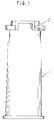
- Fig. 1 is a side view of a holder for a blood collection needle provided in an embodiment of the present invention;
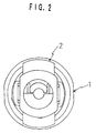
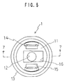
- Fig. 2 is a plan view of the holder shown in Fig. 1;
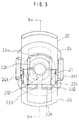
- Fig. 3 is a bottom view of a needle fixing mechanism included in the holder and shown in one position fixing the needle thereon, wherein the mechanism includes a retainer, a first slider, a second slider, and a frame;
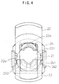
- Fig. 4 is a bottom view of the needle fixing mechanism shown in another position allowing the needle to be dismounted;
- Fig. 5 is a cross section taken along the line 5 - 5 in Fig. 3;
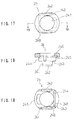
- Fig. 6 is a plan view of a cylinder included in the holder shown in Fig. 1;
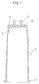
- Fig. 7 is a cross section taken along the line 7 - 7 in Fig. 6;
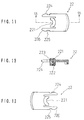
- Fig. 8 is a plan view of the retainer shown in Fig. 3;
- Fig. 9 is a bottom view of the retainer;
- Fig. 10 is a cross section taken along the line 10-10 in Fig. 8;
- Fig. 11 is a plan view of the first slider shown in Fig. 3;
- Fig. 12 is a bottom view of the first slider;
- Fig. 13 is a cross section taken along the line 13 - 13 in Fig. 11;
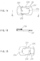
- Fig. 14 is a plan view of the second slider shown in Fig. 3;
- Fig. 15 is a bottom view of the second slider;
- Fig. 16 is a cross section taken along the line 16 - 16 in Fig. 14;
- Fig. 17 is a plan view of the frame shown in Fig. 3;
- Fig. 18 is a bottom view of the frame; and
- Fig. 19 is a cross section taken along the line 19 - 19 in Fig. 17.
- As shown in Figs. 1 and 2, the holder for a blood collection needle includes cylinder 1 and
needle fixing mechanism 2. Themechanism 2 includes two sliders:first slider 22 andsecond slider 23.Sliders first slider 22, is moved toward the other slider, e.g.,second slider 23,mechanism 2 is brought into a closed state. In this closed state,mechanism 2 can securely hold a needle by, for example, engaging a male member integral with a hub formed on the needle. On the other hand, when the situation is reversed, e.g.,second slider 23 is moved towardfirst slider 22,mechanism 2 is brought into an open state. In this open state, a needle can be removed frommechanism 2. - The holder outlined above will be described in detail referring to Figs. 3 to 19.
- As shown in Figs. 6 and 7, cylinder 1 has a distal end closed with
end wall 11, and an open proximal end.Central aperture 12 and a pair ofside openings 15 are formed in theend wall 11 of cylinder 1.Side openings 15 are used to holdneedle fixing mechanism 2.Central aperture 12 is of such a size that a cannula of the blood collection needle covered with a rubber sheath can be inserted intocentral aperture 12. A rear side of the needle carried bymechanism 2 juts into the interior of cylinder 1 so that when a blood collection tube (not shown) is inserted therein from the open proximal end thereof a rubber stopper of the tube is pierced by the needle.Side openings 15 are of such a size as to receive therethrough therespective feet 241 of a frame detailed below. Longer sides of eachopening 15 are slightly longer than the width offeet 241. Shorter sides of each of theopenings 15 are also slightly longer than the thickness ofhook 242 formed at an end of eachfoot 241. Cylinder 1 is tapered to reduce its diameter toward the distal end. It is preferred that cylinder 1 has at its proximal end aflange 13 formed integral therewith to make it easier to grip the cylinder 1. A pair ofguide fences 14 protrude from the cylinder's distal end, for ease of attaching theretoneedle fixing mechanism 2.Bottom 211 of retainer 21 (described later) fits inrecess 16 formed inend wall 11, together withbottom 222 ofengageable portion 221 offirst slider 22. A portion ofrecess 16 for receivingbottom 222 has a width slightly smaller than another portion for theother bottom 211. - The
needle fixing mechanism 2 is attached to an outer face of the cylinder'send wall 11, between and in parallel withguide fences 14. Theneedle fixing mechanism 2 includes four parts:retainer 21,first slider 22,second slider 23, andframe 24. As can best be seen in Figs. 3 and 5,retainer 21 andfirst slider 22 have halffemale members female members mechanism 2. The halffemale members first slider 22 slides away fromretainer 21 so as to release the needle. - The four parts described above as making up
needle fixing mechanism 2 are arranged relative to each other in the manner shown in Figs. 3 and 5. Such an arrangement enablesfirst slider 22 to slide towardretainer 21 and engage withframe 24, thereby causing their halffemale members grooves ceiling 246, which is a major flat portion offrame 24.Retainer 21 andfirst slider 22, which fit ingrooves Second slider 23 set onretainer 21 andfirst slider 22 has acavity 231 which accommodates theretainer 21 together with the first slider'sengageable portion 221.Frame 24 carrying themechanism 2 in the described manner will be secured to the outer face of the cylinder'send wall 11, to thereby provide the blood collection needle holder. - In the "closed" position referred to above, in which
first slider 22 havinghooks 224 andframe 24 havingguide walls 248 engage with each other,grooves 225 of thehooks 224 serve to grip firmly protrusions 243 of theguide walls 248. Thus,first slider 22 is inhibited from moving away fromretainer 21.Second slider 23 hasreleasers 232 formed integral therewith. Slanted ends of thereleasers 232 are located adjacent to or in contact with slanted ends 226 ofhooks 224, in the "closed" state of themechanism 2. Also in this "closed" state,hub pushing lug 233 ofsecond slider 23 is exposed from opening 212 through which it has passed. - In the "open" state the four parts of
needle fixing mechanism 2 take their position as shown in Fig. 4. The halffemale members retainer 21 andfirst slider 22, respectively, are spread apart from each other such that the blood collection needle is not firmly held.Grooves 225 inhooks 224 offirst slider 22 are not in engagement withprotrusions 243 ofguide walls 248 offrame 24. Thus, in such an "open" positionfirst slider 22 can slide towardretainer 21. Also in the "open" state,releasers 232, which are part ofsecond slider 23, have their ends in contact with or close toprotrusions 243 ofguide walls 248. Thehub pushing lug 233 ofsecond slider 23 will have passed the retainer'sopening 212 so as to protrude a small distance from the retainer's halffemale member 213. - As described above,
retainer 21 includes halffemale member 213 shown in Figs. 8 to 10 (member 213 being screw-threaded in the illustrated embodiment) and is fixed onframe 24.Bottom face 211 ofretainer 21 is broader than itsupper face 214, and theopening 212 for passinghub pushing lug 233 ofsecond slider 23 penetrates the portion of theretainer 21 adjacent toupper face 214. When assemblingneedle fixing mechanism 2,first slider 22 is disposed on theretainer 21 in such a manner that the former'shooks 224 rest on the latter'sbottom face 211. - Also as described above,
first slider 22 includesengageable portion 221 having halffemale member 223 shown in Figs. 11 to 13 (member 223 being screw-threaded in the illustrated embodiment), in addition to hooks 224. Andfirst slider 22 is slidable alongguide walls 248 formed upright onframe 24.Hooks 224 as locking members include a pair of arms extending in parallel with each other from outer sides ofengageable portion 221.Grooves 225 mating the frame'sprotrusions 243 are formed in outer sides ofhooks 224, and slanted ends 226 extending from the portions wheregrooves 225 are formed are tapered to reduce their width toward their extremities. The tapered surface of eachslanted end 226 extends in parallel with eachcorresponding releaser 232 ofsecond slider 23, whereby hooks 224 can flex inward when eachslanted end 226 is pushed byreleasers 232 so as to releaseprotrusions 243 fromgrooves 225. - As described above,
second slider 23 hascavity 231 defined in part between stoppingdike 234, which preventsfirst slider 22 from slipping offframe 24, and a counter wall facing same.Hub pushing lug 233 juts from the counter wall so as to pass through the retainer'sopening 212. As noted above,releasers 232 disposed outside thecavity 231 serve to disengage the frame'sprotrusions 243 from thegrooves 225 of the first slider'shooks 224. Similar tofirst slider 22,second slider 23 is also slidable along and between the frame'sguide walls 248. A pair ofcutouts 235 formed in the outer surfaces of the side walls between which thecavity 231 is defined has facing shoulders, which alternately abut againstprotrusions 243 so as to restrict the range of the longitudinal stroke ofsecond slider 23. -
Frame 24 acts as a base for holdingretainer 21,first slider 22, andsecond slider 23 on cylinder 1.Bore 247 inframe 24 is larger than the full female member composed of the halffemale members retainer 21 and the first slider'sengageable portion 221.Feet 241 offrame 24 extend downward from guide walls 248 (for guidingsliders 22 and 23) so as to secureneedle fixing mechanism 2 to cylinder 1.Protrusions 243 engageable with the hooks'grooves 225 offirst slider 22 are formed on inner faces offeet 241. The further hooks 242 protruding outward from lower end portions offeet 241 serve to secureframe 24 on cylinder 1.Recesses frame 24 are configured to receive and holdretainer 21 andfirst slider 22, respectively. - Although Figs. 3 - 5 show that both
sliders engageable portion 221 and an end facing same may be shortened infirst slider 22 shown in Figs. 11 - 13, with the distance acrosscavity 231 formed between stoppingdike 234 and a portion facing same ofsecond slider 23 shown in Figs. 14 - 16 also being reduced. In such a modified holder, onlysecond slider 23 will protrude sideways in the "closed" state, while onlyfirst slider 22 will do so in the "open" state. Thus, the release of the blood collection needle frommechanism 2 can be carried out more simply by pressing the one protruding slider (i.e., second slider 23). - The holder also may be modified such that
second slider 23 does not jut sideways from cylinder 1. For example, the distance betweenengageable portion 221 and an end facing same may be shortened infirst slider 22 shown in Figs. 11-13, with the distance acrosscavity 231 formed between stoppingdike 234 and a portion facing same ofsecond slider 23 shown in Figs. 14-16 being reduced more than the case in which only one ofsliders slider 22 norslider 23 will protrude sideways in the "closed" state, while onlyfirst slider 22 will do so in the "open" state. In this case, it is preferred thatsecond slider 23 be colored, because it is difficult to distinguish betweenfirst slider 22 andsecond slider 23. Thus, the release of the blood collection needle frommechanism 2 can be carried out by pressing the colored slider (i.e., second slider 23). The advantage ofcoloring slider 23 is that it may preventsecond slider 23 from being oriented so that it is accidently pressed by the skin, which can result in untimely release of the needle. -
Needle fixing mechanism 2 may be manufactured using any suitable material.First slider 22 andframe 24 haveflexible hooks Retainer 21 andsecond slider 23 may be made of any suitable material including flexible resins, metals, and non-flexible resins. - Those skilled in the art will recognize that
needle fixing mechanism 2 is not necessarily restricted to the structure described herein, but may be modified with respect to its structure, the number of parts, and the shapes thereof, insofar as at least two sliders are employed to cooperate with each other. For example, those skilled in the art will recognize thatfirst slider 22 may be caused to engage with and disengage fromframe 24 in a manner different from that shown in the described embodiment. In one modification, the first slider'shooks 224 may have protrusions engageable with grooves or apertures formed inframe 24, so that they are disengaged from each other by usingreleaser 232 ofsecond slider 23 as in the described embodiment. - In operation, the parts described above will function to hold and release the blood collection needle in the manner shown in Figs. 3 to 5.
- In Figs. 3 and 5, half
female member 223 of the first slider'sengageable portion 221 is positioned adjacent to halffemale member 213 ofretainer 21, withgrooves 225 of the first slider'shooks 224 being in engagement withprotrusions 243 offrame 24. In this state in whichfirst slider 22 cannot move longitudinally thereof, halffemale members - After the needle thus firmly held on
mechanism 2 is used to collect a blood sample,second slider 23 will be pushed towardfirst slider 22. Consequently,slanted releasers 232 ofsecond slider 23 will be forced to advance along and urge inward slanted ends 226 of the first slider'shooks 224.Hooks 224 thus elastically bend to an extent such that theirgrooves 225 disengage from theprotrusions 243 offrame 24. At the same time,releasers 232 will pushhooks 224 so thatfirst slider 22 is driven away from theretainer 21 and halffemale members female member 213 ofretainer 21,lug 233 is formed onsecond slider 23 so as to push the needle sideways and thereby facilitate easy removal of the needle from the holder. - After the used blood collection needle is removed from the holder,
first slider 22 will be pushed towardretainer 21 so that slanted ends 226 urge hooks 224 inward. Thus, ends 226 advance over the frame'sprotrusions 243, which consequently snap ingrooves 225 so that halffemale members - The holder described above can not only be used with a blood collection needle but also with any other appropriate medical tools such as syringes.
- It will now be apparent that users of the holder for a blood collection needle of the invention need not touch the used needle when removing same. Thus, they are protected from erroneously pricking themselves with the needle which could infect them with serious diseases. The holder offers an economic advantage because it can be used with usual medical needles whose hubs are threaded. In the case where the hubs are threaded, they are firmly held in position such that they do not unintentionally slip off, shake, or rock. Thus, medical operations for taking blood samples are now rendered much safer by the holder provided herein.
Claims (8)
- A holder for a blood connection needle comprising:a cylinder having an open proximal end, a distal end closed by an end wall, and an aperture formed in said end wall; anda needle fixing mechanism disposed at said distal end of said cylinder, said mechanism including first and second sliders, said sliders being respectively movable toward each other along said end wall, wherein when said first slider is moved toward said second slider said mechanism is brought into a closed state, and when said second slider is moved toward said first slider said mechanism is brought into an open state.
- The holder of claim 1, wherein the needle fixing mechanism includes a first slider having a half female member integrally formed thereon, a retainer having a half female member integrally formed thereon, a second slider formed such that the first slider does not slip off said cylinder, and a frame for holding the first and second sliders and said retainer on the end wall, and wherein when the first slider is moved toward the second slider said half female members come together to define a complete female member and the first slider engages said frame, and when the second slider is moved toward the first slider, the first slider disengages from said frame.
- The holder of claim 2, wherein the second slider protrudes from the frame when the first slider is in engagement with the frame, and the first slider protrudes from the frame when disengaged therefrom, and wherein the first slider is movable toward the second slider to engage with the frame, and the second slider is movable toward the first slider to disengage from the frame.
- The holder of claim 2, wherein the second slider has a lug integrally formed thereon, and the retainer has an opening through which said lug passes.
- The holder of claim 3, wherein the second slider has a lug integrally formed thereon, and the retainer has an opening through which said lug passes.
- The holder of claim 2, wherein the second slider does not protrude from the frame when the first slider is in engagement with the frame, and the first slider protrudes from the frame when disengaged therefrom, and wherein the first slider is movable toward the second slider to engage with the frame, and the second slider is movable toward the first slider to disengage from the frame.
- The holder of claim 6, wherein the second slider is colored.
- The holder for a blood collection needle comprising:a cylinder having an open proximal end, a distal end closed by an end wall, and an aperture formed in said end wall; anda needle fixing mechanism disposed at said distal end of said cylinder, said mechanism including a first slider, a second slider, a retainer, and a frame, said second slider and said retainer being disposed on said end wall, said first slider being disposed on said second slider, and said frame being affixed to said cylinder so as to hold said first slider, said second slider, and said retainer on said end wall, wherein said first slider and said retainer have half female members integrally formed thereon, said first slider is movable toward said second slider such that said mechanism is in a closed state in which said first slider engages said frame such that said half female members come together to define a complete female member, and said second slider is movable toward said first slider such that said mechanism is in an open state in which said first slider is disengaged from said frame.
Applications Claiming Priority (3)
| Application Number | Priority Date | Filing Date | Title |
|---|---|---|---|
| JP30485595 | 1995-11-22 | ||
| JP304855/95 | 1995-11-22 | ||
| JP30485595 | 1995-11-22 |
Publications (3)
| Publication Number | Publication Date |
|---|---|
| EP0780136A2 true EP0780136A2 (en) | 1997-06-25 |
| EP0780136A3 EP0780136A3 (en) | 1997-07-16 |
| EP0780136B1 EP0780136B1 (en) | 2001-08-08 |
Family
ID=17938098
Family Applications (1)
| Application Number | Title | Priority Date | Filing Date |
|---|---|---|---|
| EP96117000A Expired - Lifetime EP0780136B1 (en) | 1995-11-22 | 1996-10-23 | Holder for a blood collection needle |
Country Status (8)
| Country | Link |
|---|---|
| US (2) | US5797490A (en) |
| EP (1) | EP0780136B1 (en) |
| JP (1) | JP2723105B2 (en) |
| KR (1) | KR100281243B1 (en) |
| CN (1) | CN1130167C (en) |
| AT (1) | ATE203918T1 (en) |
| DE (1) | DE69614352T2 (en) |
| TW (1) | TW355138B (en) |
Cited By (3)
| Publication number | Priority date | Publication date | Assignee | Title |
|---|---|---|---|---|
| EP0824895A1 (en) * | 1996-07-31 | 1998-02-25 | Nissho Corporation | Infectious waste container for blood collection needles |
| EP0943352A3 (en) * | 1998-03-13 | 2000-04-12 | Becton, Dickinson and Company | Needle holder assembly |
| DE102007002096A1 (en) * | 2007-01-09 | 2008-07-10 | B. Braun Melsungen Ag | Device for injecting liquids |
Families Citing this family (33)
| Publication number | Priority date | Publication date | Assignee | Title |
|---|---|---|---|---|
| US5616136A (en) | 1995-01-09 | 1997-04-01 | Med-Safe Systems, Inc. | Quick release needle removal apparatus |
| JPH11155839A (en) * | 1997-12-02 | 1999-06-15 | Takaharu Suzuki | Vacuum blood-collecting holder |
| AT413328B (en) * | 1998-12-23 | 2006-02-15 | Greiner Bio One Gmbh | Reception unit for body fluid or tissue sampling needle insert has retaining device released via actuator provided by one-piece sliding plate with slot locating retaining device having retaining and release elements |
| AT407007B (en) * | 1998-12-23 | 2000-11-27 | Greiner Labortechnik Gmbh | RECEIVING DEVICE FOR AN INSERT ELEMENT |
| US6132402A (en) * | 1999-02-02 | 2000-10-17 | Bioform Inc. | Storage and delivery device for a catheter or needle |
| USD433505S (en) * | 1999-03-10 | 2000-11-07 | Becton Dickinson And Company | Needle holder |
| US6511440B2 (en) * | 2001-01-22 | 2003-01-28 | Long Hsiung Chen | Safety vacuum syringe for blood sampling conformed to ergonomics |
| JP2004538103A (en) * | 2001-08-09 | 2004-12-24 | ベクトン・ディキンソン・アンド・カンパニー | Retractable safety needle device |
| US6994213B2 (en) * | 2001-09-18 | 2006-02-07 | Becton, Dickinson And Company | Packaging for push button blood collection set |
| US7294118B2 (en) * | 2001-10-24 | 2007-11-13 | Becton, Dickinson And Company | Retractable needle assembly |
| US7258678B2 (en) * | 2002-03-14 | 2007-08-21 | Becton, Dickinson And Company | Retractable safety needle |
| USD484976S1 (en) | 2002-03-14 | 2004-01-06 | Becton, Dickinson And Company | Needle holder assembly |
| USD484242S1 (en) | 2002-03-14 | 2003-12-23 | Becton, Dickinson And Company | Needle holder assembly |
| JP4257943B2 (en) * | 2002-07-29 | 2009-04-30 | アークレイ株式会社 | Puncture unit and puncture member removal tool |
| US6991608B2 (en) * | 2003-04-03 | 2006-01-31 | Becton, Dickinson And Company | Medical assembly |
| US6994694B2 (en) * | 2003-08-19 | 2006-02-07 | Saftey 1St Medical, Inc. | Apparatus for retaining concentric parts within one another |
| DE10348603A1 (en) * | 2003-10-20 | 2005-05-19 | Klinika Medical Gmbh | Cannula holder comprises an unlocking mechanism which is constituted so that after its operation the cannula and/or the adapter will fall into the cannula container |
| US20060195062A1 (en) * | 2005-02-25 | 2006-08-31 | Gremel Robert F | Apparatus for locking concentric components in alignment |
| AU2006239821B2 (en) | 2005-04-22 | 2011-11-10 | Becton, Dickinson And Company | Prepackaged medical device, packaging tray, and method |
| US20070123822A1 (en) * | 2005-11-25 | 2007-05-31 | Biotop Holding Co., Ltd. | Safety syringe for taking blood |
| US7396342B2 (en) * | 2005-11-25 | 2008-07-08 | Biotop Holding Co., Ltd. | Safety syringe for taking blood |
| US20080009806A1 (en) * | 2006-07-10 | 2008-01-10 | Biotop Holding Co., Ltd. | Blood sampling device |
| US20100286558A1 (en) * | 2009-04-08 | 2010-11-11 | Stat Medical Devices, Inc. | Fluid collection/injection device having quick release/removable double-ended needle and safety system |
| US8437000B2 (en) | 2010-06-29 | 2013-05-07 | Honeywell International Inc. | Multiple wavelength cavity ring down gas sensor |
| US8269972B2 (en) | 2010-06-29 | 2012-09-18 | Honeywell International Inc. | Beam intensity detection in a cavity ring down sensor |
| US8322191B2 (en) | 2010-06-30 | 2012-12-04 | Honeywell International Inc. | Enhanced cavity for a photoacoustic gas sensor |
| US10092230B2 (en) * | 2011-04-29 | 2018-10-09 | Stat Medical Devices, Inc. | Fluid collection/injection device having safety needle assembly/cover and safety system and method |
| US9078978B2 (en) | 2011-12-28 | 2015-07-14 | Stat Medical Devices, Inc. | Needle assembly with safety system for a syringe or fluid sampling device and method of making and using the same |
| GB201304717D0 (en) * | 2013-03-15 | 2013-05-01 | Imerys Minerals Ltd | Paper composition |
| WO2018160523A1 (en) * | 2017-03-01 | 2018-09-07 | Fenwal, Inc. | Sample tube holder and system and method employing same |
| CN108968981A (en) * | 2018-06-22 | 2018-12-11 | 刘重斌 | A kind of vacuum blood collection tube |
| CN109893141B (en) * | 2019-03-15 | 2021-08-20 | 中国人民解放军陆军军医大学第二附属医院 | A fixing device for blood collection |
| CN116046473B (en) * | 2023-01-31 | 2025-08-15 | 武汉伯美帝科生物医疗科学技术有限公司 | Blood collection device and blood treatment equipment |
Citations (2)
| Publication number | Priority date | Publication date | Assignee | Title |
|---|---|---|---|---|
| JPS6428589A (en) | 1987-07-24 | 1989-01-31 | Toshiba Corp | Bottom construction of containment vessel |
| JPH02297342A (en) | 1988-09-28 | 1990-12-07 | Terumo Corp | Blood drawing and/or injection device using both cutter needle-shaped medical needle and holder, and the same medical needle and holder |
Family Cites Families (14)
| Publication number | Priority date | Publication date | Assignee | Title |
|---|---|---|---|---|
| FR1592765A (en) * | 1968-11-21 | 1970-05-19 | ||
| JPS62148646A (en) * | 1985-12-21 | 1987-07-02 | 株式会社 ニッショー | Blood sampling needle holder |
| NO164511C (en) * | 1987-12-07 | 1990-10-17 | Arild Jensen | BLOOD SAMPLING DEVICE. |
| US4892107A (en) * | 1988-01-05 | 1990-01-09 | Habley Medical Technology Corp. | Single use, safety blood collection device |
| US4942881A (en) * | 1988-04-26 | 1990-07-24 | Al Sioufi Habib | IV needle holder |
| US4951685A (en) * | 1988-05-12 | 1990-08-28 | Blair Paul A | Blood drawing system |
| US5020665A (en) * | 1988-07-01 | 1991-06-04 | John Bruno | Storage/carrying devices for transport of hypodermic needle/syringe assemblies to bedside use and ultimate disposal |
| JPH0373134A (en) * | 1989-05-19 | 1991-03-28 | Terumo Corp | Liquid collecting tube stand with holder holding jig |
| US5125414A (en) * | 1990-01-16 | 1992-06-30 | Dysarz Edward D | Trap in barrel one handed retracted blood sampling device |
| CN2104641U (en) * | 1991-09-20 | 1992-05-20 | 刘立昌 | Hemospats |
| US5401250A (en) * | 1992-10-05 | 1995-03-28 | Shields; Jack W. | Tethered conical shield for phlebotomy needles |
| CN2181260Y (en) * | 1993-11-04 | 1994-11-02 | 济南龙冠电子技术发展有限公司 | Disposable vacuum hemostix |
| US5509319A (en) * | 1994-06-21 | 1996-04-23 | Geo-Microbial Technologies, Inc. | Adapter for pipetter and hypodermic needle |
| US5685855A (en) * | 1996-07-23 | 1997-11-11 | Erskine; Timothy J. | Protected needle catheter placement device with sampling provisions and method for its use |
-
1996
- 1996-06-17 JP JP8155271A patent/JP2723105B2/en not_active Expired - Fee Related
- 1996-10-09 US US08/728,146 patent/US5797490A/en not_active Expired - Lifetime
- 1996-10-23 AT AT96117000T patent/ATE203918T1/en not_active IP Right Cessation
- 1996-10-23 EP EP96117000A patent/EP0780136B1/en not_active Expired - Lifetime
- 1996-10-23 DE DE69614352T patent/DE69614352T2/en not_active Expired - Lifetime
- 1996-10-30 TW TW085113246A patent/TW355138B/en not_active IP Right Cessation
- 1996-11-14 CN CN96120529A patent/CN1130167C/en not_active Expired - Fee Related
- 1996-11-19 KR KR1019960055326A patent/KR100281243B1/en not_active Expired - Fee Related
-
1998
- 1998-03-23 US US09/045,714 patent/US5961473A/en not_active Expired - Lifetime
Patent Citations (2)
| Publication number | Priority date | Publication date | Assignee | Title |
|---|---|---|---|---|
| JPS6428589A (en) | 1987-07-24 | 1989-01-31 | Toshiba Corp | Bottom construction of containment vessel |
| JPH02297342A (en) | 1988-09-28 | 1990-12-07 | Terumo Corp | Blood drawing and/or injection device using both cutter needle-shaped medical needle and holder, and the same medical needle and holder |
Cited By (3)
| Publication number | Priority date | Publication date | Assignee | Title |
|---|---|---|---|---|
| EP0824895A1 (en) * | 1996-07-31 | 1998-02-25 | Nissho Corporation | Infectious waste container for blood collection needles |
| EP0943352A3 (en) * | 1998-03-13 | 2000-04-12 | Becton, Dickinson and Company | Needle holder assembly |
| DE102007002096A1 (en) * | 2007-01-09 | 2008-07-10 | B. Braun Melsungen Ag | Device for injecting liquids |
Also Published As
| Publication number | Publication date |
|---|---|
| US5797490A (en) | 1998-08-25 |
| DE69614352T2 (en) | 2001-11-22 |
| US5961473A (en) | 1999-10-05 |
| JPH09201349A (en) | 1997-08-05 |
| KR100281243B1 (en) | 2001-02-01 |
| CN1130167C (en) | 2003-12-10 |
| ATE203918T1 (en) | 2001-08-15 |
| EP0780136A3 (en) | 1997-07-16 |
| CN1154230A (en) | 1997-07-16 |
| TW355138B (en) | 1999-04-01 |
| EP0780136B1 (en) | 2001-08-08 |
| JP2723105B2 (en) | 1998-03-09 |
| DE69614352D1 (en) | 2001-09-13 |
| KR970025563A (en) | 1997-06-24 |
| HK1000499A1 (en) | 2002-05-10 |
Similar Documents
| Publication | Publication Date | Title |
|---|---|---|
| EP0780136B1 (en) | Holder for a blood collection needle | |
| US5163918A (en) | Disposable safety syringe | |
| AU640018B2 (en) | Safety needle containers | |
| US4747831A (en) | Cannula insertion set with safety retracting needle | |
| US5154698A (en) | Single use syringe incorporating a sliding protection cap for the needle | |
| JP5148628B2 (en) | Safety knife with replaceable blade cartridge and safety brake | |
| CN102895719B (en) | Safety needle device with snap feature and method of making same | |
| EP0469736A1 (en) | Safety needle container | |
| US20020087180A1 (en) | Blood lancet | |
| US20050215951A1 (en) | Retracting needle safety device | |
| US20070282275A1 (en) | Safety shield apparatus and mounting structure for use with medical needle devices | |
| JP2003299735A (en) | Medical equipment | |
| EP0824895B1 (en) | Infectious waste container for blood collection needles | |
| KR20070011514A (en) | Lancet assembly | |
| JP2003534878A (en) | Liquid sampling device having a needle stored in an inclined state | |
| US5709667A (en) | Hypodermic needle protection system | |
| US5389083A (en) | Guards for hypodermic needle | |
| US6306118B1 (en) | Needle holder assembly | |
| KR20090090659A (en) | Non-reusable disposable automatic blood collection device | |
| HK1000499B (en) | Holder for a blood collection needle | |
| US7654984B2 (en) | Bodily fluid sampling or transfusion device with protection means | |
| KR20240068611A (en) | Finger grip for syringes having a flange fitting part with a protrusion structure | |
| WO2001074428A1 (en) | A retractable syringe system | |
| EP3345641A1 (en) | Safety syringes | |
| AU2001243948A1 (en) | A retractable syringe system |
Legal Events
| Date | Code | Title | Description |
|---|---|---|---|
| PUAI | Public reference made under article 153(3) epc to a published international application that has entered the european phase |
Free format text: ORIGINAL CODE: 0009012 |
|
| PUAL | Search report despatched |
Free format text: ORIGINAL CODE: 0009013 |
|
| AK | Designated contracting states |
Kind code of ref document: A2 Designated state(s): AT BE CH DE DK ES FI FR GB GR IE IT LI LU MC NL PT SE |
|
| AK | Designated contracting states |
Kind code of ref document: A3 Designated state(s): AT BE CH DE DK ES FI FR GB GR IE IT LI LU MC NL PT SE |
|
| 17P | Request for examination filed |
Effective date: 19970828 |
|
| 17Q | First examination report despatched |
Effective date: 20000320 |
|
| GRAG | Despatch of communication of intention to grant |
Free format text: ORIGINAL CODE: EPIDOS AGRA |
|
| GRAG | Despatch of communication of intention to grant |
Free format text: ORIGINAL CODE: EPIDOS AGRA |
|
| GRAH | Despatch of communication of intention to grant a patent |
Free format text: ORIGINAL CODE: EPIDOS IGRA |
|
| GRAH | Despatch of communication of intention to grant a patent |
Free format text: ORIGINAL CODE: EPIDOS IGRA |
|
| GRAA | (expected) grant |
Free format text: ORIGINAL CODE: 0009210 |
|
| AK | Designated contracting states |
Kind code of ref document: B1 Designated state(s): AT BE CH DE DK ES FI FR GB GR IE IT LI LU MC NL PT SE |
|
| PG25 | Lapsed in a contracting state [announced via postgrant information from national office to epo] |
Ref country code: NL Free format text: LAPSE BECAUSE OF FAILURE TO SUBMIT A TRANSLATION OF THE DESCRIPTION OR TO PAY THE FEE WITHIN THE PRESCRIBED TIME-LIMIT Effective date: 20010808 Ref country code: LI Free format text: LAPSE BECAUSE OF FAILURE TO SUBMIT A TRANSLATION OF THE DESCRIPTION OR TO PAY THE FEE WITHIN THE PRESCRIBED TIME-LIMIT Effective date: 20010808 Ref country code: FI Free format text: LAPSE BECAUSE OF FAILURE TO SUBMIT A TRANSLATION OF THE DESCRIPTION OR TO PAY THE FEE WITHIN THE PRESCRIBED TIME-LIMIT Effective date: 20010808 Ref country code: CH Free format text: LAPSE BECAUSE OF FAILURE TO SUBMIT A TRANSLATION OF THE DESCRIPTION OR TO PAY THE FEE WITHIN THE PRESCRIBED TIME-LIMIT Effective date: 20010808 Ref country code: BE Free format text: LAPSE BECAUSE OF FAILURE TO SUBMIT A TRANSLATION OF THE DESCRIPTION OR TO PAY THE FEE WITHIN THE PRESCRIBED TIME-LIMIT Effective date: 20010808 Ref country code: AT Free format text: LAPSE BECAUSE OF FAILURE TO SUBMIT A TRANSLATION OF THE DESCRIPTION OR TO PAY THE FEE WITHIN THE PRESCRIBED TIME-LIMIT Effective date: 20010808 |
|
| REF | Corresponds to: |
Ref document number: 203918 Country of ref document: AT Date of ref document: 20010815 Kind code of ref document: T |
|
| RIC1 | Information provided on ipc code assigned before grant |
Free format text: 7A 61M 5/34 A, 7A 61B 5/15 B |
|
| REG | Reference to a national code |
Ref country code: CH Ref legal event code: EP |
|
| RAP2 | Party data changed (patent owner data changed or rights of a patent transferred) |
Owner name: NIPRO CORPORATION |
|
| REG | Reference to a national code |
Ref country code: IE Ref legal event code: FG4D |
|
| REF | Corresponds to: |
Ref document number: 69614352 Country of ref document: DE Date of ref document: 20010913 |
|
| PGFP | Annual fee paid to national office [announced via postgrant information from national office to epo] |
Ref country code: FI Payment date: 20010919 Year of fee payment: 6 |
|
| ITF | It: translation for a ep patent filed | ||
| PGFP | Annual fee paid to national office [announced via postgrant information from national office to epo] |
Ref country code: SE Payment date: 20011005 Year of fee payment: 6 |
|
| PGFP | Annual fee paid to national office [announced via postgrant information from national office to epo] |
Ref country code: LU Payment date: 20011019 Year of fee payment: 6 |
|
| PGFP | Annual fee paid to national office [announced via postgrant information from national office to epo] |
Ref country code: ES Payment date: 20011025 Year of fee payment: 6 |
|
| PGFP | Annual fee paid to national office [announced via postgrant information from national office to epo] |
Ref country code: IE Payment date: 20011026 Year of fee payment: 6 |
|
| PGFP | Annual fee paid to national office [announced via postgrant information from national office to epo] |
Ref country code: NL Payment date: 20011031 Year of fee payment: 6 Ref country code: MC Payment date: 20011031 Year of fee payment: 6 |
|
| NLT2 | Nl: modifications (of names), taken from the european patent patent bulletin |
Owner name: NIPRO CORPORATION |
|
| PG25 | Lapsed in a contracting state [announced via postgrant information from national office to epo] |
Ref country code: SE Free format text: LAPSE BECAUSE OF FAILURE TO SUBMIT A TRANSLATION OF THE DESCRIPTION OR TO PAY THE FEE WITHIN THE PRESCRIBED TIME-LIMIT Effective date: 20011108 Ref country code: PT Free format text: LAPSE BECAUSE OF FAILURE TO SUBMIT A TRANSLATION OF THE DESCRIPTION OR TO PAY THE FEE WITHIN THE PRESCRIBED TIME-LIMIT Effective date: 20011108 Ref country code: DK Free format text: LAPSE BECAUSE OF FAILURE TO SUBMIT A TRANSLATION OF THE DESCRIPTION OR TO PAY THE FEE WITHIN THE PRESCRIBED TIME-LIMIT Effective date: 20011108 |
|
| PG25 | Lapsed in a contracting state [announced via postgrant information from national office to epo] |
Ref country code: GR Free format text: LAPSE BECAUSE OF FAILURE TO SUBMIT A TRANSLATION OF THE DESCRIPTION OR TO PAY THE FEE WITHIN THE PRESCRIBED TIME-LIMIT Effective date: 20011109 |
|
| PGFP | Annual fee paid to national office [announced via postgrant information from national office to epo] |
Ref country code: BE Payment date: 20011214 Year of fee payment: 6 |
|
| ET | Fr: translation filed | ||
| REG | Reference to a national code |
Ref country code: GB Ref legal event code: IF02 |
|
| NLV1 | Nl: lapsed or annulled due to failure to fulfill the requirements of art. 29p and 29m of the patents act | ||
| REG | Reference to a national code |
Ref country code: CH Ref legal event code: PL |
|
| PG25 | Lapsed in a contracting state [announced via postgrant information from national office to epo] |
Ref country code: ES Free format text: LAPSE BECAUSE OF FAILURE TO SUBMIT A TRANSLATION OF THE DESCRIPTION OR TO PAY THE FEE WITHIN THE PRESCRIBED TIME-LIMIT Effective date: 20020228 |
|
| PLBE | No opposition filed within time limit |
Free format text: ORIGINAL CODE: 0009261 |
|
| STAA | Information on the status of an ep patent application or granted ep patent |
Free format text: STATUS: NO OPPOSITION FILED WITHIN TIME LIMIT |
|
| 26N | No opposition filed | ||
| PG25 | Lapsed in a contracting state [announced via postgrant information from national office to epo] |
Ref country code: LU Free format text: LAPSE BECAUSE OF NON-PAYMENT OF DUE FEES Effective date: 20021023 Ref country code: IE Free format text: LAPSE BECAUSE OF NON-PAYMENT OF DUE FEES Effective date: 20021023 |
|
| PG25 | Lapsed in a contracting state [announced via postgrant information from national office to epo] |
Ref country code: MC Free format text: LAPSE BECAUSE OF NON-PAYMENT OF DUE FEES Effective date: 20030501 |
|
| REG | Reference to a national code |
Ref country code: IE Ref legal event code: MM4A |
|
| PGFP | Annual fee paid to national office [announced via postgrant information from national office to epo] |
Ref country code: FR Payment date: 20121018 Year of fee payment: 17 Ref country code: DE Payment date: 20121017 Year of fee payment: 17 |
|
| PGFP | Annual fee paid to national office [announced via postgrant information from national office to epo] |
Ref country code: IT Payment date: 20121016 Year of fee payment: 17 Ref country code: GB Payment date: 20121017 Year of fee payment: 17 |
|
| GBPC | Gb: european patent ceased through non-payment of renewal fee |
Effective date: 20131023 |
|
| PG25 | Lapsed in a contracting state [announced via postgrant information from national office to epo] |
Ref country code: GB Free format text: LAPSE BECAUSE OF NON-PAYMENT OF DUE FEES Effective date: 20131023 |
|
| REG | Reference to a national code |
Ref country code: DE Ref legal event code: R119 Ref document number: 69614352 Country of ref document: DE Effective date: 20140501 |
|
| REG | Reference to a national code |
Ref country code: FR Ref legal event code: ST Effective date: 20140630 |
|
| PG25 | Lapsed in a contracting state [announced via postgrant information from national office to epo] |
Ref country code: DE Free format text: LAPSE BECAUSE OF NON-PAYMENT OF DUE FEES Effective date: 20140501 Ref country code: FR Free format text: LAPSE BECAUSE OF NON-PAYMENT OF DUE FEES Effective date: 20131031 Ref country code: IT Free format text: LAPSE BECAUSE OF NON-PAYMENT OF DUE FEES Effective date: 20131023 |