EP0779964B1 - Ventilated cooking oven - Google Patents
Ventilated cooking oven Download PDFInfo
- Publication number
- EP0779964B1 EP0779964B1 EP95923044A EP95923044A EP0779964B1 EP 0779964 B1 EP0779964 B1 EP 0779964B1 EP 95923044 A EP95923044 A EP 95923044A EP 95923044 A EP95923044 A EP 95923044A EP 0779964 B1 EP0779964 B1 EP 0779964B1
- Authority
- EP
- European Patent Office
- Prior art keywords
- oven
- exhaust
- air
- plenum
- plenums
- Prior art date
- Legal status (The legal status is an assumption and is not a legal conclusion. Google has not performed a legal analysis and makes no representation as to the accuracy of the status listed.)
- Expired - Lifetime
Links
- 238000010411 cooking Methods 0.000 title claims description 21
- 239000003570 air Substances 0.000 claims description 79
- 239000007789 gas Substances 0.000 claims description 19
- 239000012080 ambient air Substances 0.000 claims description 3
- 239000000203 mixture Substances 0.000 claims description 3
- 235000013305 food Nutrition 0.000 description 10
- 238000004140 cleaning Methods 0.000 description 9
- 239000004519 grease Substances 0.000 description 6
- 238000010276 construction Methods 0.000 description 4
- 238000009833 condensation Methods 0.000 description 3
- 230000005494 condensation Effects 0.000 description 3
- 238000001816 cooling Methods 0.000 description 3
- 235000013410 fast food Nutrition 0.000 description 3
- 235000013550 pizza Nutrition 0.000 description 3
- 238000002485 combustion reaction Methods 0.000 description 2
- 238000010438 heat treatment Methods 0.000 description 2
- 238000012423 maintenance Methods 0.000 description 2
- 230000000694 effects Effects 0.000 description 1
- 230000005611 electricity Effects 0.000 description 1
- 235000012396 frozen pizza Nutrition 0.000 description 1
- 239000003517 fume Substances 0.000 description 1
- 238000007689 inspection Methods 0.000 description 1
- 238000004519 manufacturing process Methods 0.000 description 1
- 230000000717 retained effect Effects 0.000 description 1
Images





Classifications
-
- A—HUMAN NECESSITIES
- A21—BAKING; EDIBLE DOUGHS
- A21B—BAKERS' OVENS; MACHINES OR EQUIPMENT FOR BAKING
- A21B1/00—Bakers' ovens
- A21B1/42—Bakers' ovens characterised by the baking surfaces moving during the baking
- A21B1/48—Bakers' ovens characterised by the baking surfaces moving during the baking with surfaces in the form of an endless band
-
- F—MECHANICAL ENGINEERING; LIGHTING; HEATING; WEAPONS; BLASTING
- F24—HEATING; RANGES; VENTILATING
- F24C—DOMESTIC STOVES OR RANGES ; DETAILS OF DOMESTIC STOVES OR RANGES, OF GENERAL APPLICATION
- F24C15/00—Details
- F24C15/20—Removing cooking fumes
- F24C15/2042—Devices for removing cooking fumes structurally associated with a cooking range e.g. downdraft
Definitions
- This invention relates to one or more stackable conveyorized ovens which are ventilated so that they can be used in confined areas without emitting excessive heat or noise into the ambient atmosphere.
- conveyor ovens have been used more frequently in, for example, fast food type establishments, and in particular, in the cooking of pizza.
- one or more units are usually stacked, and each has a conveyor that passes through its own housing and oven chamber wherein convection currents of heated air are directed onto the food mounted on the conveyor.
- a frozen pizza can be loaded on the conveyor at one end, and when it emerges from the opposite end it will be fully cooked.
- Conveyor ovens have obvious advantages in minimizing the handling of the food products, uniform cooking conditions, and suitability for mass production in that typically two or three units are stacked and food can be continuously loaded and cooked. See, for example, U.S. Patent Nos. 4,960,100 and 5,231,920.
- conveyor ovens use convection currents of air and the currents are circulated by powerful fans.
- heated air from the oven chamber can be lost into the surrounding atmosphere.
- the noise from the fans and the heat generated by the ovens and expelled through the conveyor openings can be a major problem for personnel attempting to operate the ovens.
- U.S. Patent No. 4,616,562 discloses an oven with three conveyors each of which has opposite ends which project through ports in opposing side walls of the oven.
- Make-up air is delivered under positive pressure to plenums extending over the top of and down front and back walls of the oven.
- the make-up air leaves the front and back plenums to form a curtain of air extending over the opposing side walls of the oven where it mixes with fume laden cooking gas leaving the oven via the ports and is subsequently drawn upwards into an exhaust chamber situated between the top make-up air plenum and the top of the oven.
- the mixed make-up air and cooking gas then passes through a grease trap and is extracted by an exhaust fan which maintains an exhaust duct connected to the exhaust chamber at a negative pressure.
- Cool make-up air is mixed with hot cooking gas before being exhausted. This promotes condensation within the unit and increased cleaning requirements.
- the enclosure is essentially an isolated room within the kitchen which must be supported typically by the ceiling structure. Therefore, the housing creates construction problems and in addition is difficult to disassemble for cleaning or maintenance of the oven. Access to the oven for cooking or food removal is restricted by doors.
- the double-walled construction also increases space requirements and costs.
- the device of this invention does not include a canopy hood, but rather is in effect a free-standing oven with ventilated walls, or more accurately, a stack of ovens having an external ventilated shell.
- a single wall construction is used over all sides except the back wherein air makeup flows into the enclosure at the top thereof, and over the front wall; and over the top, whereupon it is expelled downwardly into the room over the back wall of the oven stack, and the exhaust fan draws room air as well as heated air from the oven into the two sides and over the top thereof to be expelled.
- the front of the oven will also have an access door for the oven interior and heated air from the baking chamber is drawn in and circulated around the sides and upwardly over the top of the device to be exhausted by the exhaust fan.
- the device of this invention effectively minimizes the noise generated by the conveyer oven fans by enclosing the stacked ovens.
- the access to the ovens for cooking and removal is readily achieved through the unobstructed sides. Access to the cooking chamber for inspection and cleaning is also available through a door in the front. In addition, the outside make-up air does not mix with the cooking gases in the exhaust. Cleaning then, is no more difficult than with conventional ovens.
- the ovens' fans which typically exhaust at the side, exhaust into a common vertical plenum which communicates with the ventilating exhaust fan which expels heated air from the baking chamber so that while the oven is cooled, heated air is not returned to the kitchen ambient.
- the vertical plenum has ambient air inlets at the base thereof. In the event the roof top exhaust fan fails, the air inlets provide an escape route for heat from the oven blower motors so they will not overheat. In the event the oven blower fails the ventilating exhaust will maintain a negative pressure in the plenum whereby, in the event the burners are gas operated, the burners will not choke.
- Figure 1 shows a prior art device consisting of a pair of stacked conveyor ovens 10 with a conventional canopy hood 12 mounted thereover.
- the conveyors 14 which are located on either side permit the expulsion of hot cooking gases into the ambient atmosphere which are intended to be sucked into the hood 12 for disposal.
- the hood 12 cannot be as effective as would be desired in, for example, the close confines of a fast food type kitchen.
- the prior art device used a double-walled structure 16 to surround the ovens with conveyors 14 extending from the entrance 15. Cooked food is removed through doors 15.
- the double wall structure 16 then is suspended or hung from the canopy 12 and surrounds the ovens on all four sides so that there is a space between the inner wall (not shown) and the oven as well as space between the inner and outer walls (also not shown) of structure 16, for air circulation. See U.S. Patent No. 5,299,557.
- This four-walled structure then is difficult to dismantle for cleaning. It also provides restricted access to the cooking chamber to remove cooked food through door 15.
- the double walls are bulky and heavy because they are intended to isolate the ovens from the ambient atmosphere.
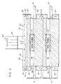
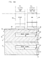
- FIG. 8 A and B
- Figures 8A and B are substantially identical side views from opposite sides.
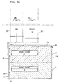
- Figure 8A illustrates the baking chamber observation door 20, whereas Figure 9A is an end view.
- Figures 8B and 9B are alternate embodiments as will be subsequently described.
- air makeup enters from fan 24' through duct 24 and is directed along the front surface 26 of ovens 10 through a conduit 28 which includes an inner baffle 30.
- the makeup air travels downwardly along the outside of baffle 30 and then upwardly along the inside of baffle 30 which places the flow of air directly along the outer skin of the ovens 10.
- a vent 32 is provided in the bottom of the structure. Air traveling along the surface of the front 26 then further is directed through a conduit 34 along the upper surface of the upper oven 10 to exit at a vent 36 in the rear 38 of the ovens 10. Vents 36 direct this air downward over the rear walls 38 of the ovens 10.
- conduits 28 and 34 are outside air makeup, and pressure in these conduits is positive. This air is expelled into the ambient atmosphere beneath and behind the stacked ovens 10.
- the airstream entering conduit 24 however, splits into a conduit 34 which forms a plenum across the upper portion of the upper oven as shown in Figures 8A and 9A.
- a series of diverter vents 29 can be provided in order to divert the stream from duct 24 into upper plenum conduit 34, or a single port as shown in Figure 9B can be used.
- the cold makeup air makes a single pass across both the front surface 26 of the oven and the upper surface thereof and both streams as in the embodiments of Figures 8A and 9A ultimately exit into the ambient atmosphere through vents 32 and 36.
- the portion of the stream exiting vent 36 is directed downwardly to wash the back surface 38 of the stacked ovens, but that surface is not otherwise housed by a conduit and no plenum is formed over the back surfaces 38 of the stacked ovens 10.
- the exhaust system essentially covers the sides and top of the stacked ovens, with the latter being layered over the air makeup conduit 34.
- a main exhaust fan 40' and conduit 40 centrally located on the top of the device. Feeding directly into exhaust conduit 40 is an upper exhaust channel 42.
- Right and left end enclosures are also provided with bottom enclosures 44 situated below the lowest conveyor, middle enclosures 46 and an upper enclosure 48.
- the latter may include optional baffles 50 as desired. If the ovens are used to cook foods having a higher grease content, these baffles 50 can serve as grease extractor baffles in an impingement device as would be obvious to one skilled in the art.
- a pair of vertical plenums 52 are disposed on the right and left front sides and an exhaust enclosure 54 is provided on the rear left side which also feeds into the upper exhaust channels 42 as shown in Figure 4.
- an exhaust enclosure 54 is provided on the rear left side which also feeds into the upper exhaust channels 42 as shown in Figure 4.
- the vertical exhaust enclosure 54 then is intended to receive the exhaust from the oven heaters through ports 54' (see Figure 4) and typically route it through conduit 42 to the exhaust conduit 40.
- the base of exhaust enclosure 54 contains a plurality of vents 55.
- Vents 55 function primarily in a failure mode situation whereby in the event of a fan failure, the burners would not necessarily be starved in the event the heating means for the ovens was gas.
- an upward draft will be achieved through negative pressure in enclosure 54 whereby ambient air will be entering on a continual basis through vents 55 to pass upwardly and to be expelled through exhaust duct 40.
- the hot cooking gases from the oven openings which receive the conveyors 14 and the heat from around the oven cabinet are drawn upwardly as shown in Figure 3 to ultimately be exhausted via exhaust fan conduit 40.
- the pressure then in the side enclosures 44, 46, and 48, and in the upper channel 42 as well as the vertical channels 52 and 54 is negative.
- Ports 56 are provided in the middle and upper side enclosures 46 and 48 to draw the cooking gases into these enclosures.
- the lower enclosure 44 generally diverts heat from around the oven skin to the exhaust.
- an enclosure 60 is provided in the right rear for a control panel (not shown) and an air makeup channel 62 is also provided for cooling the control panel.
- the ovens 10 are readily available for servicing, cleaning, and the like.
- the exterior cooling shell of this invention is supported by the oven structure itself in that the plenum chambers formed are all mounted on the ovens 10 as described hereinabove.
- Another feature of this invention which facilitates cleaning is shown, for example, with attention to Figure 10 in that the ducts 24 and 40 may be quickly disconnected from the housing itself so that the housing can be dismantled and removed from the oven, or the entire structure moved or rotated if the ovens 10 include a lower oven with rollers on its legs, as is typical.
- the ducts 24 and 40 extend downwardly and are received in corresponding duct sections for air makeup 24" and for exhaust 40". These communicate directly, as shown in Figures 8A and B and 9A and B relative to the air makeup, and in Figures 3 and 4 relative to the exhaust.
- the ducts 24 and 40 each mount a slidable, moveable collar 90 and 92, respectively, and the female sections thereof 24" and 40" mount corresponding collars 94 and 96.
- Collars 94 and 96 are immovably mounted on ducts 24" and 40" and in turn mount quick release latches 98.
- the design for the ventilated oven of this invention uses only a single outer wall with cooling air flowing generally between the oven outer skin and the outer wall of the enclosure.
- An air makeup plenum is provided across the front of the device and across the top of the device beneath the exhaust outflow channels.
- the exhaust channels flow generally upwardly along the sides and across the top. Therefore, the air makeup which enters the air makeup plenums provides a positive pressure therein whereas the channels making up the exhaust system are negative.
- the top has both an air makeup plenum extending over the oven outer skin, and the exhaust outflow, traveling above it so that air enters and leaves the system through two ports provided in the upper or top portion of the device. In this way, the need for a double wall construction is completely eliminated.
- the air makeup is exhausted into the ambient atmosphere and does not mix with the exhaust. The exhaust however includes the products of combustion from the ovens and the cooking gases from the cooking chamber.
- the exhaust in fact, is largely made up of grease in the form of vapor. If this exhaust stream comes into contact with the relatively cool air make up the grease will tend to condense within the enclosure rather than being exhausted. Obviously, such condensation will create maintenance problems.
- the structure of this invention separates the air make up from the exhaust to avoid this problem. Air make up exits the plenums into the kitchen in the vicinity of the ovens both front and back. This air ventilates and cools the oven surfaces as it mixes with the ambient atmosphere. Any air drawn into the exhaust from outside the ovens then is kitchen air which has the circulated air make up mixed therein. This design feature then minimizes grease condensation in the exhaust plenums, fan and the like. It further ventilates the kitchen as air make up mixes with kitchen air to provide a more comfortable environment for the staff.
- the device of this invention then can be integral with one or more ovens and this invention is not intended to be limited to the number of ovens stacked or the number of oven heating chambers provided within the device. It is not intended to be limited to a particular oven design, where the products of combustion are exhausted therefrom or even whether the oven is heated by gas or electricity.
- the device can be distributed in the form shown in Figures 5, 6 and 7 where it can be attached directly to existing ovens of conventional design.
- the device is intended for use with conveyor ovens and the number of side enclosures for example will depend upon the number of baking chambers or ovens stacked within the enclosure.
Landscapes
- Engineering & Computer Science (AREA)
- Life Sciences & Earth Sciences (AREA)
- Food Science & Technology (AREA)
- Chemical & Material Sciences (AREA)
- Combustion & Propulsion (AREA)
- Mechanical Engineering (AREA)
- General Engineering & Computer Science (AREA)
- Baking, Grill, Roasting (AREA)
- Devices That Are Associated With Refrigeration Equipment (AREA)
- Control And Other Processes For Unpacking Of Materials (AREA)
- Bakery Products And Manufacturing Methods Therefor (AREA)
Description
Claims (15)
- A ventilated oven structure comprisingcharacterised in that said exhaust plenums comprise exhaust side plenums (44,46,48) disposed over the side walls of said oven (10) said exhaust side plenums (44,46,48) being bounded by outer plenum walls spaced away from the oven outer skin and said vents (56) therein are formed around said oven entrance and exit ports such that exhaust gases entering the exhaust plenums (44,46,48) from the oven entrance and exit ports do not mix with make-up air which is exhausted into the ambient atmosphere from the make-up plenums (28,34).at least one conveyor oven (10) having top, front, back and side walls and having a cooking chamber (18) housed within an outer skin, a conveyor (14) extending therethrough and an entrance port and exit port in opposite side walls;make-up air plenums (28,34) including a front plenum (28) and a top plenum (34) respectively extending over the front wall of said oven (10) and over the top wall thereof said make-up plenums (28,34) being bounded by outer plenum walls spaced away from the oven outer skin and said top plenum (34) further including downwardly directed vents (36) adjacent the back wall of said oven (10);air make-up means including air make-up fan means (24') communicating with said make-up air plenums (28,34) for maintaining said make-up air plenums (28,34) at a positive pressure;exhaust plenums (44,46,48) having vents (56) therein to admit hot gases escaping from the cooking chamber into said exhaust plenums; andexhaust means including exhaust fan means (40') communicating with said exhaust plenums (44,46,48) for exhausting hot gases therefrom and for maintaining said exhaust plenums (44,46,48) at a negative pressure,
- The oven structure according to claim 1 wherein said exhaust means further includes a conduit (42) extending across said top plenum (34) communicating with said exhaust side plenums (44,46,48).
- The oven structure according to claim 1 or 2 further comprising first and second vertical exhaust plenums (52) each disposed at a junction of the oven front and side walls, and in communication with said exhaust side plenums (44,46,48) which comprise lateral conduits extending across the oven side walls, above and below the entrance and exit ports thereof.
- The oven structure according to claim 3 wherein said lateral conduits extending across said oven above each port include a plurality of said vents (56) for receiving hot gases expelled through said ports.
- The oven structure according to any preceding claim further comprising a vertical baffle plate (30) extending parallel to said oven front wall within said front plenum (28) for separating a downward flow of make-up air from the front wall of said oven (10).
- The oven structure according to claim 5 wherein said baffle plate (30) is spaced from the front plenum outer wall so that a return flow of make-up air is directed upwardly between said baffle plate (30) and oven front wall and into said top plenum (34) extending over the oven top wall.
- The oven structure according to claim 1 wherein said front plenum includes a vent (32) at the bottom thereof and said air make-up fan means (24') delivers air to the top of said front plenum (28).
- The oven structure according to any preceding claim wherein said air make-up fan means (24') delivers air to a front portion of said top plenum (34) in a stream split between said top plenum (34) and said front plenum (28).
- The oven structure according to any preceding claim wherein said conveyor oven (10) has an access door (20) in the front wall thereof and an access opening registering thereon is provided in the front plenum (28).
- The oven structure according to any preceding claim wherein said air make-up means and exhaust means each include a fan (24', 40') mounted above the top wall of said oven (10).
- The oven structure according to any preceding claim wherein a plurality of stacked conveyor ovens (10) are provided with entrance openings aligned vertically on one side and exit openings on the other side.
- The oven structure according to any preceding claim wherein said air make-up means and exhaust means include respectively an air make-up duct (24) and an air make-up fan (24') and an exhaust duct (40) and exhaust fan (40') and means for separating said ducts (24,40) and fans (24',40') from their respective plenums (28,42) including male (24,40) and female (24",40") duct sections, a pair thereof disposed between each fan (24',40') and its respective plenum (28,42) and latch means (98) for normally locking said sections together.
- The oven structure according claim 12 wherein said duct sections (24,24",40,40") each have a collar (90,92,94,96) mounted thereon and said latch means (98) engages between said collars to lock each pair of collars together.
- The oven structure according to any preceding claim wherein said oven (10) has a burner exhaust port, said structure further comprising a vertical burner exhaust plenum (54) communicating between the burner exhaust port and said exhaust fan means (40') whereby exhaust gases expelled through said burner exhaust port will be exhausted through said exhaust fan means (40') and said burner exhaust plenum (54) will be maintained at a negative pressure.
- The oven structure according to claim 14 further comprising ports (56) disposed in said exhaust burner plenum (54) below said burner exhaust port for normally admitting ambient air into said burner exhaust plenum (54), or for exhausting heated air from said oven (10) in the event that said exhaust fan means (40') fails.
Applications Claiming Priority (3)
| Application Number | Priority Date | Filing Date | Title |
|---|---|---|---|
| US298291 | 1994-08-31 | ||
| US08/298,291 US5421317A (en) | 1994-08-31 | 1994-08-31 | Ventilated cooking oven |
| PCT/US1995/007481 WO1996007057A1 (en) | 1994-08-31 | 1995-06-13 | Ventilated cooking oven |
Publications (2)
| Publication Number | Publication Date |
|---|---|
| EP0779964A1 EP0779964A1 (en) | 1997-06-25 |
| EP0779964B1 true EP0779964B1 (en) | 2000-05-17 |
Family
ID=23149870
Family Applications (1)
| Application Number | Title | Priority Date | Filing Date |
|---|---|---|---|
| EP95923044A Expired - Lifetime EP0779964B1 (en) | 1994-08-31 | 1995-06-13 | Ventilated cooking oven |
Country Status (6)
| Country | Link |
|---|---|
| US (1) | US5421317A (en) |
| EP (1) | EP0779964B1 (en) |
| AU (1) | AU682273B2 (en) |
| CA (1) | CA2197886A1 (en) |
| DE (1) | DE69517038T2 (en) |
| WO (1) | WO1996007057A1 (en) |
Families Citing this family (13)
| Publication number | Priority date | Publication date | Assignee | Title |
|---|---|---|---|---|
| US5673681A (en) * | 1996-01-17 | 1997-10-07 | Greenheck Fan Corporation | Ventilation system for conveyor oven |
| US6526961B1 (en) | 2000-07-10 | 2003-03-04 | Lincoln Foodservice Products, Inc | Conveyor oven |
| US6341601B1 (en) | 2000-12-28 | 2002-01-29 | John M. Ward | Shield for use with an oven for redirecting a thermal exhaust flow |
| US6866033B2 (en) | 2001-09-14 | 2005-03-15 | Fmc Technologies Inc. | Cooking oven damper system for regulating upper and lower flow paths |
| US6592364B2 (en) | 2001-11-30 | 2003-07-15 | David Zapata | Apparatus, method and system for independently controlling airflow in a conveyor oven |
| US20080276925A1 (en) * | 2007-05-11 | 2008-11-13 | Griswold Kevin L | Latch for oven door |
| CN102211046A (en) * | 2010-04-09 | 2011-10-12 | 鸿富锦精密工业(深圳)有限公司 | Constant temperature cabinet |
| CN105451564B (en) * | 2013-06-17 | 2018-01-12 | W.C.布拉德利公司 | For the high-efficiency appliance and method cooked, heated and dry |
| US9677774B2 (en) | 2015-06-08 | 2017-06-13 | Alto-Shaam, Inc. | Multi-zone oven with variable cavity sizes |
| US10890336B2 (en) | 2015-06-08 | 2021-01-12 | Alto-Shaam, Inc. | Thermal management system for multizone oven |
| US10088172B2 (en) | 2016-07-29 | 2018-10-02 | Alto-Shaam, Inc. | Oven using structured air |
| US10337745B2 (en) | 2015-06-08 | 2019-07-02 | Alto-Shaam, Inc. | Convection oven |
| US9879865B2 (en) | 2015-06-08 | 2018-01-30 | Alto-Shaam, Inc. | Cooking oven |
Family Cites Families (9)
| Publication number | Priority date | Publication date | Assignee | Title |
|---|---|---|---|---|
| US4383823A (en) * | 1981-06-12 | 1983-05-17 | Williams Robert W | Radiant oven for baking bread |
| US4643167A (en) * | 1985-04-02 | 1987-02-17 | Pizza Hut, Inc. | Oven ventilation system |
| US4616562A (en) * | 1985-06-21 | 1986-10-14 | Kuechler Irvin R | Ventilation system for pizza ovens |
| US4738243A (en) * | 1987-01-12 | 1988-04-19 | Ldi Mfg. Co., Inc. | Hood system for conveyorized cooking oven |
| US4960100A (en) * | 1989-03-13 | 1990-10-02 | Mastermatic, Inc. | Conveyor oven |
| US4896657A (en) * | 1989-05-25 | 1990-01-30 | Glassman Joseph T | Exhaust hood system and method for pizza ovens |
| US5299557A (en) * | 1991-02-04 | 1994-04-05 | Pizza Hut, Inc. | Oven enclosure and ventilation system |
| US5231920A (en) * | 1991-09-19 | 1993-08-03 | G. S. Blodgett Corporation | Conveyor oven with uniform air flow |
| US5421320A (en) * | 1994-05-27 | 1995-06-06 | Ldi Mfg. Co., Inc. | Conveyor oven exhaust system |
-
1994
- 1994-08-31 US US08/298,291 patent/US5421317A/en not_active Expired - Lifetime
-
1995
- 1995-06-13 DE DE69517038T patent/DE69517038T2/en not_active Expired - Fee Related
- 1995-06-13 WO PCT/US1995/007481 patent/WO1996007057A1/en not_active Ceased
- 1995-06-13 CA CA002197886A patent/CA2197886A1/en not_active Abandoned
- 1995-06-13 AU AU27748/95A patent/AU682273B2/en not_active Ceased
- 1995-06-13 EP EP95923044A patent/EP0779964B1/en not_active Expired - Lifetime
Also Published As
| Publication number | Publication date |
|---|---|
| DE69517038D1 (en) | 2000-06-21 |
| AU2774895A (en) | 1996-03-22 |
| CA2197886A1 (en) | 1996-03-07 |
| US5421317A (en) | 1995-06-06 |
| EP0779964A1 (en) | 1997-06-25 |
| WO1996007057A1 (en) | 1996-03-07 |
| AU682273B2 (en) | 1997-09-25 |
| DE69517038T2 (en) | 2001-02-15 |
Similar Documents
| Publication | Publication Date | Title |
|---|---|---|
| AU682273B2 (en) | Ventilated cooking oven | |
| CA2041872C (en) | Air delivery system and oven control circuitry cooling system for a low profile impingement oven | |
| US5421320A (en) | Conveyor oven exhaust system | |
| US6854457B2 (en) | Convection oven and related cooking air flow system | |
| US4865010A (en) | Exhaust duct cooling system for built-in gas oven | |
| US5816234A (en) | Convection oven | |
| CA2194202C (en) | Ventilation system for conveyor oven | |
| US4616562A (en) | Ventilation system for pizza ovens | |
| EP2524171B1 (en) | Oven exhaust hood method and device | |
| AU643128B2 (en) | Oven enclosure and ventilation system | |
| US6192877B1 (en) | Blown air distributor for a convection oven | |
| CA2454010C (en) | Ventilation system for a cooking appliance | |
| EP0512716B1 (en) | Cooking apparatus | |
| JPH04214129A (en) | Burner stove | |
| GB2256921A (en) | Oven | |
| GB2039029A (en) | A gas oven with two oven compartments | |
| EP0726425B1 (en) | Built-in cooking device - cooling | |
| US5626127A (en) | Clean face air circulating fireplace | |
| AU2017372764A1 (en) | Cooling system for an oven door of a cooking oven | |
| US5866886A (en) | Triangular shaped air inlet for an over-the-range type oven | |
| KR0132999Y1 (en) | Cooling apparatus of oven range | |
| JP2005270380A (en) | Warm storage | |
| KR200141514Y1 (en) | Cooling apparatus of door in a oven range | |
| US12553618B2 (en) | Cooking appliance | |
| JPH08320140A (en) | Exhaust unit with hood having no ventilating hole |
Legal Events
| Date | Code | Title | Description |
|---|---|---|---|
| PUAI | Public reference made under article 153(3) epc to a published international application that has entered the european phase |
Free format text: ORIGINAL CODE: 0009012 |
|
| 17P | Request for examination filed |
Effective date: 19970401 |
|
| AK | Designated contracting states |
Kind code of ref document: A1 Designated state(s): DE FR GB |
|
| 17Q | First examination report despatched |
Effective date: 19980902 |
|
| GRAG | Despatch of communication of intention to grant |
Free format text: ORIGINAL CODE: EPIDOS AGRA |
|
| GRAG | Despatch of communication of intention to grant |
Free format text: ORIGINAL CODE: EPIDOS AGRA |
|
| GRAH | Despatch of communication of intention to grant a patent |
Free format text: ORIGINAL CODE: EPIDOS IGRA |
|
| GRAH | Despatch of communication of intention to grant a patent |
Free format text: ORIGINAL CODE: EPIDOS IGRA |
|
| GRAA | (expected) grant |
Free format text: ORIGINAL CODE: 0009210 |
|
| AK | Designated contracting states |
Kind code of ref document: B1 Designated state(s): DE FR GB |
|
| REF | Corresponds to: |
Ref document number: 69517038 Country of ref document: DE Date of ref document: 20000621 |
|
| ET | Fr: translation filed | ||
| PLBE | No opposition filed within time limit |
Free format text: ORIGINAL CODE: 0009261 |
|
| STAA | Information on the status of an ep patent application or granted ep patent |
Free format text: STATUS: NO OPPOSITION FILED WITHIN TIME LIMIT |
|
| 26N | No opposition filed | ||
| REG | Reference to a national code |
Ref country code: GB Ref legal event code: IF02 |
|
| PGFP | Annual fee paid to national office [announced via postgrant information from national office to epo] |
Ref country code: FR Payment date: 20030610 Year of fee payment: 9 |
|
| PGFP | Annual fee paid to national office [announced via postgrant information from national office to epo] |
Ref country code: GB Payment date: 20030611 Year of fee payment: 9 |
|
| PGFP | Annual fee paid to national office [announced via postgrant information from national office to epo] |
Ref country code: DE Payment date: 20030626 Year of fee payment: 9 |
|
| PG25 | Lapsed in a contracting state [announced via postgrant information from national office to epo] |
Ref country code: GB Free format text: LAPSE BECAUSE OF NON-PAYMENT OF DUE FEES Effective date: 20040613 |
|
| PG25 | Lapsed in a contracting state [announced via postgrant information from national office to epo] |
Ref country code: DE Free format text: LAPSE BECAUSE OF NON-PAYMENT OF DUE FEES Effective date: 20050101 |
|
| GBPC | Gb: european patent ceased through non-payment of renewal fee |
Effective date: 20040613 |
|
| PG25 | Lapsed in a contracting state [announced via postgrant information from national office to epo] |
Ref country code: FR Free format text: LAPSE BECAUSE OF NON-PAYMENT OF DUE FEES Effective date: 20050228 |
|
| REG | Reference to a national code |
Ref country code: FR Ref legal event code: ST |