EP0779864B1 - Writing tool - Google Patents
Writing tool Download PDFInfo
- Publication number
- EP0779864B1 EP0779864B1 EP96923038A EP96923038A EP0779864B1 EP 0779864 B1 EP0779864 B1 EP 0779864B1 EP 96923038 A EP96923038 A EP 96923038A EP 96923038 A EP96923038 A EP 96923038A EP 0779864 B1 EP0779864 B1 EP 0779864B1
- Authority
- EP
- European Patent Office
- Prior art keywords
- tip
- rod
- liquid
- coiled spring
- writing tool
- Prior art date
- Legal status (The legal status is an assumption and is not a legal conclusion. Google has not performed a legal analysis and makes no representation as to the accuracy of the status listed.)
- Expired - Lifetime
Links
- 239000007788 liquid Substances 0.000 claims abstract description 211
- 238000000638 solvent extraction Methods 0.000 claims description 33
- 230000002093 peripheral effect Effects 0.000 claims description 5
- 238000005192 partition Methods 0.000 claims description 2
- 238000010276 construction Methods 0.000 abstract description 21
- 238000012546 transfer Methods 0.000 abstract description 2
- 238000003825 pressing Methods 0.000 description 19
- 238000004891 communication Methods 0.000 description 16
- 238000012545 processing Methods 0.000 description 10
- 239000000470 constituent Substances 0.000 description 9
- 238000000034 method Methods 0.000 description 9
- 230000008569 process Effects 0.000 description 6
- 230000008602 contraction Effects 0.000 description 4
- 230000000694 effects Effects 0.000 description 4
- 238000012986 modification Methods 0.000 description 4
- 230000004048 modification Effects 0.000 description 4
- 230000000704 physical effect Effects 0.000 description 4
- 238000005516 engineering process Methods 0.000 description 3
- 238000004519 manufacturing process Methods 0.000 description 3
- 230000005484 gravity Effects 0.000 description 2
- 238000010348 incorporation Methods 0.000 description 2
- 239000002244 precipitate Substances 0.000 description 2
- 239000007787 solid Substances 0.000 description 2
- 230000009471 action Effects 0.000 description 1
- 238000012937 correction Methods 0.000 description 1
- 230000001771 impaired effect Effects 0.000 description 1
- 230000006872 improvement Effects 0.000 description 1
- 230000001939 inductive effect Effects 0.000 description 1
- 238000003780 insertion Methods 0.000 description 1
- 230000037431 insertion Effects 0.000 description 1
- 230000009467 reduction Effects 0.000 description 1
- 238000009877 rendering Methods 0.000 description 1
- 239000011347 resin Substances 0.000 description 1
- 229920005989 resin Polymers 0.000 description 1
- 239000002904 solvent Substances 0.000 description 1
Images







Classifications
-
- B—PERFORMING OPERATIONS; TRANSPORTING
- B43—WRITING OR DRAWING IMPLEMENTS; BUREAU ACCESSORIES
- B43K—IMPLEMENTS FOR WRITING OR DRAWING
- B43K1/00—Nibs; Writing-points
- B43K1/08—Nibs; Writing-points with ball points; Balls or ball beds
- B43K1/086—Nibs; Writing-points with ball points; Balls or ball beds with resilient supporting means for the ball, e.g. springs
Definitions
- the present invention relates to a writing tool, and particularly to a tip of the writing tool in the form of a valve construction which is designed so that a rotary body embraced in a ball house within the extreme end of a tip connected to the extreme end of a liquid tank filled with ink or an applying liquid is urged forward by means of a coiled spring inserted and present within the tip into contact an inwardly directed extreme end edge so that the ink or the applying ink does not flow out, and that when in use, the rotary body a part of which is projected from the extreme end of the tip is pressed against a paper surface to retreat the rotary body against the force of the coiled spring whereby the ink or the applying liquid is transferred onto a paper.
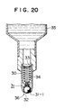
- the tip of the writing tool of this kind has been generally known so far in the construction exemplified in Fig. 20 (as disclosed in Japanese Utility Model Laid-Open No. Hei 6-11873) and in EP-A-621141.
- a tip 30 of the conventional writing tool is designed so that a rotary body 32 is embraced in a ball house 31 within the extreme end thereof, a washer 33 is provided by pressing within the rear end of the tip 30, and a coiled spring 34 having substantially the same length as that of the tip 30 is inserted and provided between the washer 33 and the rotary body 32 whereby the rotary body is urged forward by means of the coiled spring 34 to cause the rotary body 32 to come in contact with an inwardly directed extreme end edge 31-1 of the ball house 31 so that an applying ink within a liquid tank 35 does not flow out of a liquid applying port 36 of the ball house 31. That is, the rotary body 32 and the inwardly directed extreme end edge 31-1 of the ball house 31 constitute a valve construction so that the applying liquid does not flow out of the liquid applying port 36.
- the tip used in the writing tool of this kind is formed from a relatively small diameter metallic pipe. Accordingly, the coiled spring incorporated and inserted into the tip has to be formed so as to have a smaller diameter, for which processing, a high degree of processing technology is required, and simultaneously therewith, for incorporation thereof into the tip, an incorporating technology with high precision is also required. Accordingly, since the conventional writing tool is constructed such that the rotary body is urged forward by means of the coiled spring having the length substantially over the full length within the tip to cause it to come in contact with the inwardly directed extreme end edge of the tip, the processing cost for the coiled spring increases. That is, the coiled spring need be processed to be a lengthy type which is about the same length as that of the tip using the processing technology of high degree, thus increasing the processing cost for the coiled spring.
- the coiled spring since the coiled spring is arranged over the full length within the tip, the coiled spring forms an obstacle which impedes a flow of an applying liquid being fed from a liquid tank to a ball house at the extreme end thereof passing through the tip to bring about a liquid run-out in that the applying liquid breaks during use.
- the coiled spring when the coiled spring is incorporated and inserted into the tip, it is necessary that in the state where one end of the coiled spring is placed in contact with the rotary body within the ball house, the coiled spring is inserted and arranged in the tip and in the state where a suitable (spring) force is applied to the coiled spring, a washer for causing the other end of the coiled spring to place in contact is provided within the rear end of the tip by pressing.
- a washer for causing the other end of the coiled spring to place in contact is provided within the rear end of the tip by pressing.
- the coiled spring is sometimes incorporated into the tip with the state where the core is deviated. Even if when incorporated, the coiled spring should be properly inserted into the tip in the centered state, since the coiled spring is not supported, the deviation in core would occur during use for a short period of time. When the deviation in core occurs, it is difficult to urge the rotary body forward in well balanced manner, thus making it difficult to evenly place the rotary body in contact with the inwardly-directed extreme end edge of the ball house. That is, the positivism of the closed state of the valve construction constituted by the rotary body and the inwardly-directed extreme end edge of the ball house is impaired so that the applying liquid carelessly flows out. The improvement therefor has been desired.
- the applying liquid within the tip returns to the liquid tank with its own weight. If the applying liquid within the tip does not quickly return to the liquid tank, the applying liquid remaining in the tip becomes solidified as the time passes to induce the inoperable state of expansion and contraction of the coiled spring resulting in an disable condition. That is, there induces an open- and closing disabling condition of the valve construction caused by the movement of the rotary body and the clogging therein.
- the tip of the aforementioned conventional writing tool is designed so that a washer having a liquid passage port which is smaller than a diameter of the tip is provided interiorly of the rear end thereof so as to place the coiled spring within the tip. Therefore, even if the writing tool is put with the tip directed upward after use, the clogging phenomenon occurs in the liquid passage port of the washer so that the ink or the applying liquid does not return to the liquid tank but remains within the tip to bring about the aforementioned inconveniences.
- the rotary body and the coiled spring may be incorporated into the tip by first putting the rotary body into the ball house from the opening at the extreme end of the tip, and caulking the open edge at the extreme end thereof inwardly to rotatably embrace the rotary body therein. Thereafter, the procedure is performed in which the coiled spring is placed in contact with the rotary body from the opening at the rear end of the tip, and the other end thereof is inserted to be projected relative to the ball house.
- an object of the present invention is to reduce the processing cost for processing a coiled spring.
- a further object of the invention is to simply and positively perform centering relative to a core of a tip when the coiled spring is incorporated into the tip, and even after incorporation and insertion, to firmly support the coiled spring within the tip in the state where no deviation in center occurs.
- Another object of the invention is to quickly supply an ink or an applying liquid to a ball house without being subjected to flow resistance.
- Still another object of the invention is to stand the tool with the tip upward whereby ink or an applying liquid remaining in the tip may return to a liquid tank quickly.
- writing tool comprising a tubular tip at a front end of which is contained in a ball house in the tip a rotary writing body which engages a seat formed at the front end of the tubular tip by an inwardly directed portion of the tip, a coiled spring which urges the body so that a part thereof projects from the front end of the tip, said ball house being connected to a liquid tank in the writing tool, characterised in that the coiled spring is of less length than the tip, and a spring supporting rod is fixed to the rear end of the tip by being telescoped into the tip from its rear end and has at its front end a spring support portion which supports the spring concentrically in the tip at the front end of the tip, and by a liquid inducting passage leading from the rear end to the front end of the spring supporting rod.
- the spring support portion has a spring support bore which is shorter than the length of the coiled spring and is larger in inside diameter than the outside diameter of the coiled spring which bore receives one end of the coiled spring for the support of said spring.
- the spring support bore preferably has a stopping shoulder of substantially the same diameter as the outside diameter of the coiled spring, and one end of the coiled spring is fixedly mounted and supported by the stopping shoulder by being pressed or screwed thereto.
- the rod may have at the rear end a large diameter fixed portion defining a shoulder relative to the remainder of the rod, said portion having a diameter substantially equal to the inside diameter of the tip, by which portion the rod is fixed to the tip.
- the outside diameter of the rod from the shoulder to the front end of the rod is smaller in diameter than the inside diameter of the tip, whereby a second liquid conducting passage is formed between the rod and the tip, and there is a liquid flow hole extending from the rear end of said large diameter portion to the shoulder, which hole leads to the second liquid conducting passage.
- the liquid conducting passage may be concentrically arranged in the rod and extends from the rear end of the rod to the spring extending for the length of the spring support portion and opening into said passage.
- the liquid conducting passage is concentrically arranged and extends from the rear end of the rod to the spring support portion and there is a plurality of peripherally arranged, liquid conducting slits (21) in the spring support portion opening into the liquid conducting passage.
- liquid conducting grooves peripherally arranged on the outer surface of the rod, which extend from the rear end of the rod to the spring support portions.
- the rod may comprise a partitioning portion extending from the rear end of the rod to the spring support portion, said partition portion having a width which is substantially the same as the inside diameter of the tip, the rod being fixed to the tip by the partitioning portion, said liquid conducting passage lying between said partitioning portion and the inner surface of the tip.
- the rod may have an integral tail end portion which projects from the rear end of the partitioning portion towards the liquid tank and has the same thickness as said partitioning portion.
- Fig. 1A is a longitudinal sectional view showing a first embodiment of writing tool according to the present invention
- Fig. 1B is an enlarged view of 1B section of Figure 1A
- Fig. 2 is a longitudinal sectional view showing a process in which a coiled spring is incorporated into a tip
- Fig. 3 is a partly enlarged view showing a further embodiment of a supporting mode of the coiled spring with respect to a spring support portion
- Fig. 4 is a longitudinal sectional view showing a further modification
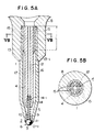
- Fig. 5A is a longitudinal sectional view showing a second embodiment of writing tool according to the present invention
- Fig. 5B is a cross sectional view taken on line VB-VB of Fig. 5A
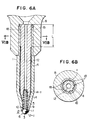
- FIG. 6A is a longitudinal sectional view showing a third embodiment of writing tool according to the present invention
- Fig. 6B is a cross sectional view taken on line VIB-VIB of Fig. 6A
- Fig. 7A is a longitudinal sectional view showing a fourth embodiment of writing tool according to the present invention
- Fig. 7B is a cross sectional view taken on line VIIB-VIIB of Fig. 7A
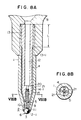
- Fig. 8A is a longitudinal sectional view showing a fifth embodiment of writing tool according to the present invention
- Fig. 8B is a cross sectional view taken on line VIIIB-VIIIB of Fig. 8A
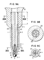
- Fig. 9A is a longitudinal sectional view showing a sixth embodiment of writing tool according to the present invention
- Fig. 9A is a longitudinal sectional view showing a sixth embodiment of writing tool according to the present invention
- Fig. 9A is a longitudinal sectional view showing a sixth embodiment of writing tool according to the present invention
- Fig. 9A is
- FIG. 9B is a cross sectional view taken on line IXB-IXB of Fig. 9A;
- Fig. 9C is a cross sectional view taken on line IXC-IXC of Fig. 9A;
- Fig. 10A is a longitudinal sectional view of main parts showing another embodiment;
- Fig. 10B is a cross sectional view taken on line XB-XB of Fig. 10A;
- Fig. 11A is a longitudinal sectional view showing a seventh embodiment of writing tool according to the present invention;
- Fig. 11B is a cross sectional view taken on line XIB-XIB of Fig. 11A;
- Fig. 11C is a cross sectional view taken on line XIC-XIC of Fig. 11A;
- FIG. 11D is a cross sectional view taken on line XID-XID of Fig. 11A;
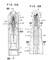
- Fig. 12A is a longitudinal sectional view showing a eighth embodiment of writing tool according to the present invention;
- Fig. 12B is an enlarged view of XIIB of Fig. 12A;
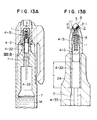
- Fig. 13A is a longitudinal sectional view taken on line XIII-XIII of Fig. 12A;
- Fig. 13B is an enlarged view of XIIIB section of Fig. 13A;
- Fig. 14 is an enlarged cross sectional view taken on line XIV-XIV of Fig. 12B;
- Fig. 15 is an enlarged cross sectional view taken on line XV-XV of Fig. 12B;
- Fig. 12A is a longitudinal sectional view showing a eighth embodiment of writing tool according to the present invention;
- Fig. 12B is an enlarged view of XIIB of Fig. 12A;
- FIG. 16 is a partial enlarged view showing another embodiment of the supporting mode of the coiled spring with respect to the spring supporting tubular portion;
- Fig. 17 is a longitudinal sectional view showing one example of the using state for correcting erroneously written portions or the like;
- Fig. 18 is a longitudinal sectional view of main parts showing another embodiment of the projecting mode of a tail end portion;
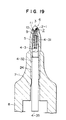
- Fig. 19 is likewise a longitudinal sectional view of main parts showing still another embodiment of the projecting mode of the tail end portion;
- Fig. 20 is a longitudinal sectional view showing the conventional writing tool.
- FIGs. 1A to 3 show a first embodiment of the writing tool of the present invention according to claims 1 to 3.
- a rotary body 3 is rotatably embraced within a ball house 2 at the extreme end of a tip 1, and the rotary body 3 is urged forward by means of a coiled spring 5 supported by a telescope 4, incorporated and arranged into contact with an inwardly directed extreme end edge 2-1 of the ball house 2 so that ink or an applying liquid M does not flow out of a liquid applying port 6.
- the rotary body 3 and the inwardly directed extreme end edge 2-1 of the ball house 2 constitute a valve construction so that when not in use, ink or an applying liquid M does not flow out of a liquid applying port 6, it being connected through a holder 8 to the extreme end of a liquid tank 7 of a pen type or a bottle type by pressing.
- the tip 1 is formed from a metallic pipe or the like so that the extreme end is converged, within the extreme end of which is formed the ball house 2 defined in a communication manner by a seat portion 11 having a center liquid conducting hole 9 and a radial longitudinal groove 10, and the rotary body 3 is rotatably embraced within the ball house 2.
- a telescope 4 supporting a coiled spring 5 for urging the rotary body 3 in the direction of the inwardly directed extreme end edge 2-1 of the ball house 2 to cause the rotary body 3 to spring contact with the extreme end edge 2-1.
- the coiled spring 5 has its full length formed to be shorter than the length of the tip 1.
- the coiled spring 5 is formed to be short in length about 1/3 to 1/4 of the length of the tip 1, one end (rear end) thereof being concentrically supported on the extreme end of the telescope 4 and incorporated and inserted into the tip 1 while the other end (extreme end) thereof being loosely projected into the ball house 2 from a liquid conducting hole 9 in the center of the seat portion 11 to place it in spring contact with the rotary body 3 so that the rotary body 3 is brought into contact with the inwardly directed extreme end edge 2-1 of the ball house 2.
- the telescope 4 comprises a resin molded article which has a function to concentrically support the coiled spring 5 within the tip 1, and to conduct ink or the applying liquid M from the liquid tank 7 to the vicinity of the ball house 2 in which the rotary body 3 at the extreme end of the tip 1 is embraced, the telescope 4 having the outside diameter smaller than the inside diameter of the tip 1 and the length from the opening at the rear end of the tip 1 to the vicinity of the seat portion 11, being provided with a liquid conducting portion 12 extending through the core in the form of a hole directed at the front and rear ends and being formed in the form of a rod with a shoulder provided with a large diameter fixed portion 13 secured by pressing into the tip 1 with a suitable range L in an axial direction from the rear end.
- a spring support portion 14 for supporting one end of the coiled spring 5 is concentrically provided on the extreme end side formed to be converged adjusting to the end shape of the tip 1.
- the large diameter fixed portion 13 has a function to firmly and concentrically fix the telescope 4 within the tip 1 by pressing. In other words, it has a function to firmly and concentrically fix the coiled spring 5, which repeats compressed deformation by pressing of the rotary body 3 against the paper surface, within the tip 1, the large diameter fixed portion 13 being formed to have a diameter which is substantially the same as the inside diameter of the tip 1 within a suitable distance L in an axial direction from the rear end of the telescope 4 and being firmly fixed within the tip 1 by pressing so as to center the telescope 4 with respect to the core of the tip 1.
- the telescope 4 is inserted within the tip 1 in a loosened state (in a non-contact state) with a slight clearance relative to the inner surface of the tip 1 other than the large diameter fixed portion on the rear end side in a state of being incorporated within the tip 1. Therefore, it is possible to positively and simply center the telescope 4 with respect to the core of the tip 1.
- the large diameter fixed portion 13 is formed with a suitable distance L axially from the rear end. Therefore, when the telescope 4 supporting the coiled spring 5 is incorporated into the tip 1 as shown in Fig. 2, the proximal end 13-1 of the shoulder of the large diameter fixed portion 13 is pressed into the opening at the rear end of the tip 1 and at the same time, the telescope 4 is centered to the core of the tip 1.
- the telescope 4 is pressed into the tip 1, and at the same time, on the other side of the coiled spring 5, the centering of the seat portion 11 of the ball house 2 relative to the core of the liquid conducting hole 9 is effected so that the telescope 4 can be loosely projected into the ball house 2 in a state where the coiled spring 5 is positively centered with respect to the core of liquid conducting hole 9.
- the other end of the coiled spring 5 does not possibly impinge upon the liquid conducting hole 9 but the other end of the coiled spring 5 can be projected into the ball house 2 quickly into contact with the rotary body 3, thus considerably simplifying the incorporating operation of the coiled spring 5 into the tip 1 as compared with the conventional writing tool to improve the workability thereof.
- the spring support portion 14 is concentrically formed from the extreme end of the telescope 4 with a hole diameter which is shallower than the length of the coiled spring 5 and larger than the outside diameter of the coiled spring 5, the hole bottom being communicated with the liquid conducting portion 12, the coiled spring 5 being supported with one end loosely immersed.
- the hole bottom of the spring support portion 14 in communication with the liquid conducting portion 12 is provided with a stopping shoulder 14-1 having a diameter which is substantially the same as the outside diameter of the coiled spring 5, and one end portion of the coiled spring 5 loosely inserted in an immersed manner is fixed and supported by pressing.
- the coiled spring 5 Since the coiled spring 5 is firmly secured to and supported on the stopping shoulder 14-1, the coiled spring 5 is not deviated from the core of the tip 1 but causes the rotary body 3 to contact the inwardly directed extreme end edge 2-1 (the entire periphery of the edge) of the ball house 2 in a well balanced manner and evenly to provide the positivity of the closed state of the valve construction constituted by the inwardly directed extreme end edge 2-1 of the ball house 2 and the rotary body 3. This prevents a careless flow-out of ink or the applying liquid M.
- the fixing means for fixing and supporting one end of the coiled spring 5 to the stopping shoulder 14-1 of the spring support portion 14 is not limited to the pressing but various means can be considered such as means in which as shown in Fig. 3, the stopping shoulder 14-1 is provided with a helical groove 15 so that several winds on one end side of the coiled spring 5 by screwing to support it by screwing.
- the number of processes can be reduced as compared with the lengthy coiled spring of the conventional writing tool as far as the length of the coiled spring 5 is shortened about 1/3 to 1/4 of the length of the tip 1 for which processing technique of high degree is required, thus enabling the production of the coiled spring 5 at low cost and the reduction of the process cost of the coiled spring 5.
- the ink or the applying liquid within the liquid tank is supplied to the ball house at the extreme end of the tip passing through the liquid conducting portion leading to the front and rear ends of the telescope, the flow of the ink or the applying liquid M within the liquid tank 7 supplied to the ball house 2 is less impeded as compared with the tip construction of the conventional writing tool in which the coiled spring is inserted and arranged over the full length within the tip. Thereby, the ink or the applying liquid can be supplied to the ball house quickly.
- the coiled spring 5 When the coiled spring 5 is incorporated into and mounted in the tip 1, the coiled spring 5 together with the telescope 4 can be inserted into the tip 1 in the state where one end side of the coiled spring 5 is loosely immersed into the coil support portion 1 of the telescope 4 formed in the form of a rod with a shoulder having the liquid conducting portion 12 extended through toward the spring support portion 14 at the extreme end on the core, in the length from the opening at the rear end of the tip 1 to the vicinity of the ball house 2 at the extreme end, and having the large diameter fixed portion 13 fixedly inserted by pressing into the tip 1 on the rear end side, and in the state where the one end side thereof is firmly secured to and supported on the stopping shoulder 14-1.
- the coiled spring 5 can be loosely projected toward the ball house 2 and placed in (spring) contact with the rotary body 3 in the state where the coiled spring 5 is centered to the core of the liquid conducting hole 9 in the center of the seat portion 11 of the ball house 2 at the extreme end of the tip 1 and without occurrence of deviation in core, thus providing the positivity of the closed state of the valve construction constituted by the inwardly directed extreme end edge 2-1 of the ball house 2 and the rotary body 3 to prevent a careless flow-out of ink or the applying liquid M, as described above.
- the ink or the applying liquid M within the liquid tank 7 is guided to the vicinity of the ball house 2 passing through the liquid conducting portion 12 of the core of the telescope 4 from the rear end of the tip 1 to the vicinity of the ball house 2 at the extreme end thereof and the spring support portion 12 in communication with the liquid conducting portion 12 and fed to the ball house 2 quickly. Therefore, no liquid run-out occurs during the use as in the conventional writing tool.
- the centering of the telescope with respect to the core of the tip is simpler than the incorporating construction of the telescope for fixedly incorporating the entire outer surface of the telescope in the state in contact with the inner surface of the tip.
- the processing number of finishing the outer surface of the telescope applied for the purpose of centering and of surface finishing such as inner surface finishing of the tip is reduced, thus reducing the manufacturing cost.
- Fig. 4 shows a modification in which the length of the telescope 4-1 is shortened as a whole.
- the hole shape of the tip 1 is formed into a shape with a shoulder so that the large diameter fixed portion 13 of the telescope 4-1 can be pressed and fixed at the extreme end side. Since this modification is basically the same as the first embodiment described above except that the length of the telescope 4-1 and the hole shape of the tip 1 in the writing tool described in the first embodiment are changed, the description thereof is omitted using the same reference numerals for the same constituent parts.
- the telescope 4-1 is formed to have the length formed with the large diameter fixed portion 13 in the above-described range of length L in the outer periphery thereof except the extreme end having the spring support portion 14.
- the telescope 4-1 is short about 1/3 of the length of the telescope 4.
- the tip 1 has a diameter L 1 on the extreme end side thereof formed so that the large diameter fixed portion 13 of the telescope 4-1 can be fixed by pressing and has a diameter L 2 from the part on the extreme end to the opening at the rear end formed into a hole with a shoulder through which the large diameter fixed portion 13 can pass in a loosened state.
- Figs. 5A and 5B show a second embodiment of the writing tool of the present invention, wherein the large diameter fixed portion 13 of the telescope 4 is provided with a liquid flowing hole 15 extending through from the rear end thereof toward a shoulder proximal end 13-1, and a diameter (outside diameter) of the telescope 4 extending from the shoulder proximal end 13-1 to the open edge of the spring support portion 14 is formed to be smaller than the inside diameter of the tip 1 so as to secure a second liquid conducting portion 16 for guiding ink or an applying liquid M having passed through the liquid flowing hole 15 toward the vicinity of the seat portion 11 of the ball house 2 in the inner surface of the tip 1 from the shoulder proximal end 13-1 of the large diameter fixed portion 13 to the open edge of the spring support portion 14.
- the second embodiment is basically the same in construction as that of the first embodiment described in detail except that the large diameter fixed portion 13 is provided with a liquid flowing hole 15, and the diameter of the telescope 4 extending from the proximal end shoulder 13-1 of the large diameter fixed portion 13 to the open edge of the spring support portion 14 is made small, the description thereof is omitted using the same reference numerals for the same constituent parts.
- the diameter (outside diameter) of the telescope 4 in the range from the proximal end shoulder 13-1 of the large diameter fixed portion 13 to be firmly fixed into the tip 1 by pressing to the open edge of the spring support portion 14 is formed to be smaller by two or three times of the inside diameter of the tip 1 so that a small diameter loose portion 17 loosely present in the tip 1 is provided so as to secure a second liquid conducting portion 16 having an open sectional area through which ink or an applying liquid M can pass quickly in the inner surface of the tip 1.
- a plurality of liquid flowing holes 15 are peripherally provided (see Fig. 5B) which extend through in a suitable open shape from the proximal end shoulder 13-1 of the large diameter fixed portion 13 relative to the small diameter loose portion 17 toward the rear end (the rear end of the telescope 4) thereof.
- the second liquid conducting portion 16 having an open sectional area through which ink or an applying liquid M passes is secured between the small diameter loose portion 17 from the shoulder proximal end 13-1 of the large diameter fixed portion 13 to the open edge of the spring support portion 14 at the extreme end of the telescope 4.
- the ink or the applying liquid M within the liquid tank 7 passes through the liquid conducting portion 12 leading to the spring support portion 14 of the core of the telescope 4 for supporting the coiled spring 5 in an immersed state, each of the liquid flowing holes 15 from the rear end of the telescope 4 to the shoulder proximal end 13-1 of the large diameter fixed portion 13, and is guided to the vicinity of the ball house 2 by which the rotary body 3 at the extreme end of the tip 1 is embraced passing through the second liquid conducting portion 16 secured relative to the inner surface of the tip 1. Therefore it is possible to supply the ink or the applying liquid M to the ball house 2 quickly.
- the telescope 4 described in detail in the second embodiment can be formed to be short as shown in Fig. 4 and fixedly inserted into the extreme end of the tip 1.
- Figs. 6A and 6B show a third embodiment of the writing tool of the present invention, wherein a plurality of fixed longitudinal ribs 18 projected at a projecting height having substantially the same diameter as the inside diameter of the tip 1 described in detail in the aforementioned first embodiment are provided on the rear end side of the telescope 4, and the fixed longitudinal ribs 18 are pressed into the tip 1 to fixedly insert the telescope 4 into the tip 1.
- the third embodiment is basically the same in construction as that of the first embodiment described in detail except that the fixed longitudinal ribs 18 are provided on the rear end side of the telescope 4 in place of the large diameter fixed portion 13 secured into the tip 1 by pressing in the writing tool described in the first embodiment, the description thereof is omitted using the same reference numerals for the same constituent parts.
- the fixed longitudinal ribs 18 have a function to press the telescope 4 into the tip 1 similar to the large diameter fixed portion 13 to thereby firmly and concentrically fix it.
- a plurality of such ribs are peripherally provided on the rear end side of the telescope 4 at a projecting height having substantially the same diameter as the inside diameter of the tip 1 within the suitable distance L axially from the rear end of the telescope 4, and such ribs are provided at three to eight locations as shown in Fig. 6b peripherally equidistantly and pressed against the inner surface of the tip 1 at peripheral three to eight-point supports so as to firmly fix the telescope 4 within the tip 1.
- the telescope 4 when the telescope 4 is inserted into the tip 1, the telescope 4 is fixedly inserted into the tip 1 in the state where the fixed longitudinal ribs 18 provided on the rear end side are pressed against the inner surface of the tip 1 in a mode of axial line contact.
- the centering of the telescope 4 with respect to the core of the tip 1 is further simpler than the incorporating construction of the telescope described in detail in the first and second embodiments.
- the telescope 4 can be centered relative to the core of the tip 1 without so much affected by the precision of the surface finish such as the inner surface finish of the tip 1 of a portion (range of distance L) in which the telescope 4 is fixedly pressed.
- the outer surface finish of the telescope 4 for centering is not necessary, and the inner surface finish of the tip 1 will suffice to be rough. Therefore, the number of processes for the surface finish can be further reduced as compared with the incorporating construction of the telescope described in detail in the first and second embodiments, and in addition, the manufacturing cost can be further reduced, which is advantageous.
- Figs. 7A and 7B show a fourth embodiment of the writing tool of the present invention, wherein the open configuration of the spring support portion 14 in communication with the liquid conducting portion 12 of the telescope 4 is changed, and a liquid conducting longitudinal groove 19 is provided from the liquid conducting portion 12 toward the open edge of the spring support portion 14 so that ink or applying liquid is supplied from the liquid conducting portion 12 to the ball house 2 at the extreme end without subjecting to the flow resistance and efficiently.
- the fourth embodiment is basically the same in construction as that of the first embodiment described in detail except that the open configuration of the spring support portion 14 from the liquid conducting portion 12 to the open edge in the writing tool described in the first embodiment, and the liquid conducting longitudinal groove 19 is provided, the description thereof is omitted using the same reference numerals for the same constituent parts.
- the spring support portion 14 is concentrically provided, from the extreme end of the telescope 4 toward the vicinity of the liquid conducting portion 12, with a diameter smaller than that of the liquid conducting portion 12, and a small diameter portion 20 having a smaller diameter than the first mentioned diameter is concentrically provided toward the liquid conducting portion 12 into communication with the latter.
- a liquid conducting longitudinal groove 19 is provided from the communication proximal end of the liquid conducting portion 12 with the small diameter portion 20 toward the open edge of the spring support portion 14.
- the liquid conducting longitudinal groove 19 has a function to quickly guide ink or an applying liquid M under the capillary action from the liquid conducting portion 12 toward the open edge of the spring support portion 14 coaxially located in the vicinity of the ball house 2 at the extreme end of the tip 1, several of which are peripherally provided from the communication proximal end of the liquid conducting portion 12 with the small diameter portion 20 with a depth along the inner surface of the liquid conducting portion 12 (see Fig. 7B).
- the liquid conducting longitudinal groove 19 is provided from the communication proximal end of the liquid conducting portion of the telescope 4 core with the small diameter portion toward the open edge of the spring support portion 14.
- the ink or applying liquid having flown to the communication proximal end with the small diameter portion passing through the liquid conducting portion 12 is guided to the vicinity of the ball house 2 at the extreme end of the tip 1 under the capillary acting on the liquid conducting longitudinal groove 19 directed at the open edge of the spring support portion 14 without subjecting to the flow resistance caused by the coiled spring 5 supported on the spring support portion 14 in an immersed state.
- the ink or applying liquid can be quickly supplied to the ball house 2 without the flow being impeded by the coiled spring 5 supported on the spring support portion 14 in an immersed state.
- the telescope 4 described in detail in the fourth embodiment is formed to be short as shown in Fig. 4 and fixedly inserted into the extreme end of the tip 1.
- Figs. 8A and 8B show a fifth embodiment of the writing tool of the present invention, wherein in place of the liquid conducting longitudinal groove 19 described in detail in the fourth embodiment, there is provided a liquid conducting slit 21 which is opened from the communication proximal end with the small diameter portion 20 of the liquid conducting portion 12 toward the open edge of the spring support portion 14 and toward the outer surface of the telescope 4. Since the fifth embodiment is basically the same in construction as that of the fourth embodiment described in detail except that the liquid conducting slit 21 is provided instead, the description thereof is omitted using the same reference numerals for the same constituent parts.
- ink or an applying liquid M from the liquid tank 7 passes through the liquid conducting portion 12 of the telescope 4 core leading to the spring support portion 14 for supporting the coiled spring 5 in an immersed state, passes through the liquid conducting slit 21 opened from the liquid conducting portion 12 toward the open edge of the spring support portion 14 and is guided to the vicinity of the ball house 2 in which the rotary body 3 at the extreme end of the tip 1 is embraced.
- the ink or the applying liquid M having flown through the liquid conducting portion 12 of the telescope 4 core is guided to the vicinity of the ball house 2 passing through the liquid conducting slit 21, which is enlarged in its open sectional area, without being impeded in flow by the coiled spring 5 supported on the spring support portion 14 in an immersed state.
- the telescope 4 described in detail in the fifth embodiment is likewise formed to be short as shown in Fig. 4 and fixedly inserted into the extreme end of the tip 1.
- Figs. 9A, 9B and 9C show a sixth embodiment of the writing tool of the present invention, wherein as described in detail in the first embodiment, a groove-like liquid conducting portion 22 leading to the front and rear portions is provided in the outer surface of the telescope 4-2 formed into a rod with a shoulder having a large diameter fixed portion 13 at the rear end thereof with a length from the rear end opening of the tip 1 toward the vicinity of the seat portion 11 of the ball house 2 at the extreme end of the tip 1 in which the rotary body 3 is embraced, and ink or an applying liquid M in the liquid tank is supplied to the ball house 2 quickly passing through the groove-like liquid conducting portion 22 from the rear end of the tip 1 to the vicinity of the seat portion 11 of the ball house 2 at the extreme end.
- the sixth embodiment is basically the same in construction as that of the first embodiment described in detail except that the opening configuration of the liquid conducting portion 22 with respect to the telescope 4-2 is changed, the description thereof is omitted using the same reference numerals for the same constituent parts.
- Several groove-like liquid conducting portions 22 are peripherally provided on the outer surface with a suitable open shape communicated with the spring support portion 14 from the peripheral surface thereof from the rear end of the telescope 4-2 toward the converged extreme end, i.e., the open edge of the spring support portion 14 (see Figs. 9B and 9C), and the ink or the applying liquid M in the liquid tank 7 passes through quickly, is guided to the vicinity of the seat portion 11 of the ball house 2 at the extreme end of the tip 1, and is supplied to the ball house 2.
- the groove-like opened liquid conducting portion 22 can secure considerably largely a communication opening sectional area for feeding ink or an applying liquid M toward the ball house 2 at the extreme end of the tip 1. Thereby, this can cope with the flowability of the ink or the applying liquid M which differs with the physical properties such as viscosity, surface tension or specific gravity, etc. Accordingly, there can be expected the effect that even the ink or the applying liquid M having the wide physical properties according to the purpose of using the writing tool can be quickly supplied to the ball house 2 at the extreme end of the tip 1.
- the telescope 4-2 described in detail in the sixth embodiment is likewise formed to be short as shown in Fig. 4 and fixedly inserted into the extreme end of the tip 1.
- the groove-like liquid conducting portion 22 in the outer peripheral surface of the telescope 4-2 and the spring support portion 14 are not made in communication but independent of each other as shown in Figs. 10A and 10B.
- Figs. 11A, 11B, 11C and 11D show a seventh embodiment of the writing tool of the present invention, wherein a telescope 4-3 is formed to have a length from the rear end opening of the tip 1 to the vicinity of the ball house 2 at the extreme end thereof from a spring supporting tubular portion 4-31 for supporting the other end of the coiled spring 5 in an immersed state and a partitioning portion 4-32 integrally extended from the rear end of the spring supporting tubular portion 4-31, and the partitioning portion 4-32 is pressed into the tip 1 to fixedly insert the telescope 4-3 so as to secure a liquid conducting portion 23 relative to the inner surface of the tip 1 with the partitioning portion 4-32 put therebetween.
- the seventh embodiment is basically the same in construction as that of the first embodiment described in detail except that the constituent configuration of the telescope 4-3 itself is changed, the description thereof is omitted using the same reference numerals for the same constituent parts.
- the spring support tubular portion 4-31 is formed to be closed-end tubular having a desired wall-thickness and which is shorter than the length of the coiled spring 5 whose length is short about 1/3 to 1/4 of the length of the tip 1 and whose diameter is larger than the outside diameter of the coiled spring 5, more specifically, a diameter to such a degree that the coiled spring 5 is not in contact with the inner surface of the spring support tubular portion 4-31 in the state where the other end of the coiled spring 5 is concentrically immersed so as to support the coiled spring 5 in the state where one end thereof is loosely inserted and immersed.
- the hole bottom of the spring support tubular portion 4-31 is provided with a stopping shoulder 14-1 having a diameter which is substantially the same as the outside diameter of the coiled spring 5, and one end portion of the coiled spring 5 loosely inserted in an immersed manner is fixed and supported by pressing, as described in detail in the first embodiment.
- the partitioning portion 4-32 is to secure a liquid conducting portion 23 having a desired opening sectional area relative to the inner surface of the tip 1 in the range from the rear end opening of the tip 1 to the spring support tubular portion 4-31 concentrically present in the vicinity of the seat portion 11 of the ball house 2.
- the partitioning portion 4-32 is integrally extended from the rear end part of the spring support tubular portion 4-31 with a suitable thickness capable of firmly secured to the inner surface of the tip 1 by pressing and with a width narrower than the inside diameter (diameter) of the tip 1.
- a wide fixed portion 24 is formed with substantially the same width as the inside diameter of the tip 1 within a suitable distance 1 and firmly fixed within the tip 1 by pressing to center the telescope 4-3 with respect to the core of the tip 1.
- the writing tool described in detail in the seventh embodiment similarly to the aforementioned sixth embodiment, it can secure considerably largely an opening sectional area for feeding ink or an applying liquid M toward the ball house 2 at the extreme end of the tip 1. Therefore, this can cope with the flowability of the ink or the applying liquid M which differs with the physical properties such as viscosity, surface tension or specific gravity, etc. Accordingly, there can be expected the effect that even the ink or the applying liquid M having the wide physical properties according to the purpose of using the writing tool can be quickly supplied to the ball house 2 at the extreme end of the tip 1.
- the writing tool described in detail in the first to seventh embodiments according to the present invention can be manufactured and provided at low cost from the fact that the number of processes can be reduced, as compared with the lengthy coiled spring of the conventional writing tool, for a portion that the length of the coiled spring for which processing technique of high degree is required, and that when the coiled spring is incorporated into the tip, centering can be made simply and positively with respect to the core of the tip and the incorporating operation can be considerably simplified as compared with the conventional writing tool.
- the ink or the applying liquid does not flow out carelessly, and no liquid breakage induces during the use, as in the conventional writing tool.
- Figs. 12A to 19 show an eighth embodiment of the writing tool of the present invention, wherein in the writing tool described in detail in the seventh embodiment, a tail end portion 4-33 to be projected toward the liquid tank 7 with the same thickness as that of at least the partitioning portion 4-32 from the partitioning portion 4-32 located substantially in the same plane is integrally extended at the rear end opening of the tip 1 whereby after use, the writing tool is stood with the tip 1 directed upward so that ink or an applying liquid within the tip 1 is transmitted to the partitioning portion 4-32 of the telescope 4-3 present in the tip 1, is transmitted to the tail end portion 4-33 extending to the liquid tank 7 without being broken from the partitioning portion 4-32 and is quickly returned to the liquid tank 7. Since the eighth embodiment is basically the same in construction as that of the seventh embodiment described in detail except that the tail end portion 4-33 is integrally extended from the rear end of the telescope 4-3, the description thereof is omitted using the same reference numerals for the same constituent parts.
- the tail end portion 4-33 has a function that when the writing tool is stood on a pen stand or the like with the tip 1 directed upward after the use for such as correction of erroneously written portions, the ink or the applying liquid M is not broken at a part of the rear end opening of the tip 1, that is, ink or an applying liquid M in a liquid conducting port 7-1 of the liquid tank 7 having the tip 1 connected by pressing from the part of the rear end opening of the tip 1, and at the extreme end within the liquid tank 7 in the vicinity of the liquid conducting port 7-1 returns to the rear end side (tail end side) of the liquid tank 7 due to its own weight, a flow of which is not broken at the part of the rear end opening of the tip 1, and the ink or the applying liquid M together with the partitioning portion 4-32 is quickly guided toward the light tank 7 in such a manner as to be pulled by the flow to return it into the liquid tank 7 (liquid conducting function).
- the tail end portion is extended in the form of an angular rod having a square in cross section which is concentrically loosely inserted into the liquid conducting port 7-1 of the liquid tank 7 from the center of the rear end widthwise of the partitioning portion 4-32 and having the same thickness a that of the partitioning portion 4-32 with a length to an extent to be projected into the liquid tank 7 (see Fig. 14).
- the hole bottom (tubular bottom) of the spring support tubular portion 4-31 shown in Fig. 16 is provided with a stopping shoulder 25 having a diameter which is substantially the same as the outside diameter of the coiled spring 5, and one end portion of the coiled spring 5 loosely inserted in an immersed manner is fixed and supported by pressing or screwing, as described in detail in the first embodiment.
- the ink or the applying liquid in the tip 1 is transmitted to the partitioning portion 4-32 of the telescope 4-3, is transmitted to the tail end portion 4-33 loosely inserted into the liquid conducting port 7-1 of the liquid tank 7 from the rear end of the partitioning portion 4-32 located substantially in the same plane as the rear end opening of the tip 1 and projected in the form of an angular rod toward the liquid tank 7, and is quickly returned to the liquid tank 7.
- the ink or the applying liquid M which is not returned to the liquid tank 7 but remains in the tip 1 is solidified as the time passes and the coiled spring 5 having a function to urge the rotary body 3 toward the inwardly directed extreme end edge 2-1 of the ball house 2 is place in an inoperative state in expansion and contraction to render it unusable.
- Figs. 18 and 19 show another embodiment in which the projecting configuration of the tail end portion 4-33 described in detail in the above-described embodiment.
- a tail end portion 4-34 shown in Fig. 18 is extended in a gradually converged manner from both edges widthwise of the rear end of the partitioning portion 4-32 toward its projecting halfway part (solid line) or its projecting end (two-dot contour line).
- a tail end portion 4-35 shown in Fig. 19 is extended in a web-like manner having substantially the same width as that of the partitioning portion 4-32.
- the these tail end portions 4-34 and 4-35 have a function such that they are extended from the rear end of the partitioning portion 4-32 with the same thickness as that of the partitioning portion 4-32, and when the writing tool is stood on a pen stand or the like with the tip 1 directed upward after use, the ink or the applying liquid M within the tip 1 returns to the liquid conducting port 7-1 of the liquid tank 7 from the part of the rear end opening of the tip 1, and the ink or the applying liquid M at the extreme end in the liquid tank 7 in the vicinity of the liquid conducting port 7-1 returns to the rear end (tail end) of the liquid tank 7 due to its own weight, a flow of which causes the ink or the applying liquid M in the tip 1 together with the partitioning portion 4-32 to conduct toward the liquid tank 7 without being broken at the part of the rear end opening of the tip 1 and so as to be pulled by the flow and return into the liquid tank 7.
- the writing tool of the present invention described in detail in the eighth embodiment has the function and effect, in addition to those described in the seventh embodiment, in that when the writing tool is stood on a pen stand or the like after use, the ink or the applying liquid in the tip is transmitted to the partitioning portion of the telescope present in the tip, is transmitted to the tail end portion extending to the liquid tank without being broken from the partitioning portion and is returned into the liquid tank.
- the ink or the applying liquid which is not returned to the liquid tank but remains in the tip is solidified as the time passes and the coiled spring having a function to urge the rotary body toward the inwardly directed extreme end edge of the ball house is place in an inoperative state in expansion and contraction to render it unusable, as in the conventional writing tool.
Landscapes
- Pens And Brushes (AREA)
- Surgical Instruments (AREA)
- Thin Film Transistor (AREA)
- Acyclic And Carbocyclic Compounds In Medicinal Compositions (AREA)
Abstract
Description
Claims (11)
- A writing tool comprising a tubular tip (1) at a front end of which is contained in a ball house (2) in the tip (1) a rotary writing body (3) which engages a seat (2-1) formed at the front end of the tubular tip (1) by an inwardly directed portion (2-1) of the tip, a coiled spring (5) which urges the body (3) so that a part thereof projects from the front end of the tip (1), said ball house (2) being connected to a liquid tank (7) in the writing tool, characterised in that the coiled spring (5) is of less length than the tip (1), and a spring supporting rod (4) is fixed to the rear end of the tip (1) by being telescoped into the tip (1) from its rear end and has at its front end a spring support portion which supports the spring (5) concentrically in the tip at the front end of the tip (1), and characterised by a liquid inducting passage (12) leading from the rear end to the front end of the spring supporting rod (4).
- The writing tool according to claim 1, wherein the spring support portion has a spring support bore (14) which is shorter than the length of the coiled spring (5) and is larger in inside diameter than the outside diameter of the coiled spring (5) which bore (14) receives one end of the coiled spring (5) for the support of said spring (5).
- The writing tool according to claim 2, wherein the spring support bore (14) has a stopping shoulder (15) of substantially the same diameter as the outside diameter of the coiled spring (5), and one end of the coiled spring is fixedly mounted and supported by the stopping shoulder (15) by being pressed or screwed thereto.
- The writing tool according to claim 1, 2 or 3, wherein the rod (4) has at the rear end a large diameter fixed portion (13) defining a shoulder (13-1) relative to the remainder of the rod (4), said portion (13) having a diameter substantially equal to the inside diameter of the tip (1), by which portion (13) the rod (4) is fixed to the tip (1).
- The writing tool according to claim 4, wherein the outside diameter of the rod (4) from the shoulder (13-1) to the front end of the rod (4) is smaller in diameter than the inside diameter of the tip (1), whereby a second liquid conducting passage is formed between the rod (4) and the tip (1), and there is a liquid flow hole (13-1) extending from the rear end of said large diameter portion (13) to the shoulder, which hole (13-1) leads to the second liquid conducting passage.
- The writing tool according to claim 1, 2, 3 or 4, wherein at the rear end of the rod (4) there is a plurality of fixed peripheral longitudinal ribs (18) projecting to a height to have substantially the same diameter as the inside diameter of the tip (1) by which the rod (4) is fixed to the tip (1).
- The writing tool according to claim 1, 2, 3 or 4 wherein the liquid conducting passage (12) is concentrically arranged in the rod (4) and extends from the rear end of the rod (4) to the spring support portion and there is a plurality of peripherally arranged liquid conducting longitudinal grooves (19) in the spring support portion extending for the length of the spring support portion and opening into said passage (12).
- The writing tool according to claim 1, 2, 3 or 4 wherein the liquid conducting passage (12) is concentrically arranged and extends from the rear end of the rod (4) to the spring support portion and there is a plurality of peripherally arranged, liquid conducting slits (21) in the spring support portion opening into the liquid conducting passage (12).
- The writing tool according to claim 1, 2, 3 or 4, wherein there is a plurality of liquid conducting grooves (22), peripherally arranged on the outer surface of the rod (4), which extend from the rear end of the rod (4) to the spring support portion.
- A writing tool according to claim 1, 2, 3 or 4 wherein the rod (4) comprises a partitioning portion (4-32) extending from the rear end of rod (4) to the spring support portion, said partition portion (4-32) having a width which is substantially the same as the inside diameter of the tip (1), the rod (4) being fixed to the tip (1) by the partitioning portion (4-32), said liquid conducting passage (23) lying between said partitioning portion (4-32) and the inner surface of the tip (1).
- The writing tool according to claim 10, wherein the rod (4) has an integral tail end portion (4-33) which projects from the rear end of the partitioning portion (4-32) towards the liquid tank (7) and has the same thickness as said partitioning portion (4-32).
Applications Claiming Priority (7)
| Application Number | Priority Date | Filing Date | Title |
|---|---|---|---|
| JP17865595 | 1995-07-14 | ||
| JP178655/95 | 1995-07-14 | ||
| JP7178655A JPH08300875A (en) | 1995-03-07 | 1995-07-14 | Writing instrument |
| JP23145895 | 1995-09-08 | ||
| JP231458/95 | 1995-09-08 | ||
| JP7231458A JPH0976685A (en) | 1995-09-08 | 1995-09-08 | Writing implement |
| PCT/JP1996/001903 WO1997003845A1 (en) | 1995-07-14 | 1996-07-10 | Writing tool |
Publications (2)
| Publication Number | Publication Date |
|---|---|
| EP0779864A1 EP0779864A1 (en) | 1997-06-25 |
| EP0779864B1 true EP0779864B1 (en) | 2000-03-01 |
Family
ID=26498766
Family Applications (1)
| Application Number | Title | Priority Date | Filing Date |
|---|---|---|---|
| EP96923038A Expired - Lifetime EP0779864B1 (en) | 1995-07-14 | 1996-07-10 | Writing tool |
Country Status (6)
| Country | Link |
|---|---|
| US (1) | US6042290A (en) |
| EP (1) | EP0779864B1 (en) |
| AT (1) | ATE190013T1 (en) |
| DE (1) | DE69606841D1 (en) |
| TW (1) | TW509149U (en) |
| WO (1) | WO1997003845A1 (en) |
Families Citing this family (7)
| Publication number | Priority date | Publication date | Assignee | Title |
|---|---|---|---|---|
| US6027272A (en) | 1998-06-19 | 2000-02-22 | The Gillette Company | Fluid delivery system |
| DE69923423T2 (en) * | 1998-08-21 | 2005-06-09 | Kabushiki Kaisha Pilot Corp.(Also Trading As Pilot Corp.) | BUTTON WRITING INSTRUMENT |
| JP3393102B2 (en) * | 2000-02-17 | 2003-04-07 | 株式会社東京サインペン | Ballpoint pen tip |
| US6446549B1 (en) * | 2000-11-16 | 2002-09-10 | Carla B. Soucie | Hand-held paper embossing tool |
| EP1270080B1 (en) * | 2001-06-19 | 2010-01-27 | Ford Global Technologies, LLC | Device and method of applying lubricant |
| US20050279231A1 (en) * | 2004-06-17 | 2005-12-22 | Lee Chung H | Embossing stylus |
| US20050279230A1 (en) * | 2004-06-17 | 2005-12-22 | Lee Chung H | Embossing stylus |
Family Cites Families (7)
| Publication number | Priority date | Publication date | Assignee | Title |
|---|---|---|---|---|
| US2107424A (en) * | 1936-07-18 | 1938-02-08 | Celanese Corp | Marking device |
| US2930062A (en) * | 1958-12-03 | 1960-03-29 | Tri Chem Inc | Ball type applicators |
| FR2203750A1 (en) * | 1972-10-19 | 1974-05-17 | Cherrier Yves | |
| US3819285A (en) * | 1973-02-22 | 1974-06-25 | Mark Tex Corp | Pressurized marking device |
| US3902815A (en) * | 1974-04-01 | 1975-09-02 | Liquid Paper Corp | Positive displacement dispenser |
| JP2797847B2 (en) * | 1992-06-25 | 1998-09-17 | 富士ゼロックス株式会社 | Electrophotographic photoreceptor |
| JP2550236Y2 (en) * | 1993-04-23 | 1997-10-08 | セーラー万年筆株式会社 | Applicator |
-
1996
- 1996-05-30 TW TW088200368U patent/TW509149U/en not_active IP Right Cessation
- 1996-07-10 US US08/793,602 patent/US6042290A/en not_active Expired - Fee Related
- 1996-07-10 WO PCT/JP1996/001903 patent/WO1997003845A1/en not_active Ceased
- 1996-07-10 DE DE69606841T patent/DE69606841D1/en not_active Expired - Lifetime
- 1996-07-10 AT AT96923038T patent/ATE190013T1/en not_active IP Right Cessation
- 1996-07-10 EP EP96923038A patent/EP0779864B1/en not_active Expired - Lifetime
Also Published As
| Publication number | Publication date |
|---|---|
| DE69606841D1 (en) | 2000-04-06 |
| TW509149U (en) | 2002-11-01 |
| ATE190013T1 (en) | 2000-03-15 |
| EP0779864A1 (en) | 1997-06-25 |
| US6042290A (en) | 2000-03-28 |
| WO1997003845A1 (en) | 1997-02-06 |
Similar Documents
| Publication | Publication Date | Title |
|---|---|---|
| EP2860045B1 (en) | Ballpoint pen | |
| KR100235906B1 (en) | Ball- point pen refill and method of manufacturing the same | |
| EP0779864A1 (en) | Writing tool | |
| JP2679874B2 (en) | Writing tool | |
| JP4870444B2 (en) | Chip for applicator and applicator | |
| JP3416677B2 (en) | Applicator | |
| JP2009029056A (en) | Ballpoint pen | |
| KR950010819A (en) | Cosmetic Containers | |
| WO1997030854A1 (en) | Direct ink storing type writing instrument | |
| JP3007035B2 (en) | Ballpoint pen refill | |
| JP2555677Y2 (en) | Ballpoint pen | |
| JP4906104B2 (en) | Ballpoint pen refill | |
| US6322270B1 (en) | Tip assembly of ball point pen | |
| JPH0230309Y2 (en) | ||
| US20090047056A1 (en) | Encapsulated fiber type writing instrument | |
| JP3304906B2 (en) | Tip of ball type liquid container | |
| JP2880865B2 (en) | Writing implement | |
| KR101950402B1 (en) | Retractable type writing instrument | |
| JPH0333506Y2 (en) | ||
| JP2005035177A (en) | Ballpoint pen | |
| KR200342412Y1 (en) | Tip for Writing Instrument | |
| JP3085921B2 (en) | Writing instrument tip | |
| JPH09123668A (en) | Liquid type writing instrument | |
| JPS6144865Y2 (en) | ||
| KR940007201Y1 (en) | pen |
Legal Events
| Date | Code | Title | Description |
|---|---|---|---|
| PUAI | Public reference made under article 153(3) epc to a published international application that has entered the european phase |
Free format text: ORIGINAL CODE: 0009012 |
|
| 17P | Request for examination filed |
Effective date: 19970308 |
|
| AK | Designated contracting states |
Kind code of ref document: A1 Designated state(s): AT DE FR GB IT |
|
| 17Q | First examination report despatched |
Effective date: 19980212 |
|
| GRAG | Despatch of communication of intention to grant |
Free format text: ORIGINAL CODE: EPIDOS AGRA |
|
| GRAG | Despatch of communication of intention to grant |
Free format text: ORIGINAL CODE: EPIDOS AGRA |
|
| GRAH | Despatch of communication of intention to grant a patent |
Free format text: ORIGINAL CODE: EPIDOS IGRA |
|
| GRAH | Despatch of communication of intention to grant a patent |
Free format text: ORIGINAL CODE: EPIDOS IGRA |
|
| GRAA | (expected) grant |
Free format text: ORIGINAL CODE: 0009210 |
|
| ITF | It: translation for a ep patent filed | ||
| AK | Designated contracting states |
Kind code of ref document: B1 Designated state(s): AT DE FR GB IT |
|
| PG25 | Lapsed in a contracting state [announced via postgrant information from national office to epo] |
Ref country code: AT Free format text: LAPSE BECAUSE OF FAILURE TO SUBMIT A TRANSLATION OF THE DESCRIPTION OR TO PAY THE FEE WITHIN THE PRESCRIBED TIME-LIMIT Effective date: 20000301 |
|
| REF | Corresponds to: |
Ref document number: 190013 Country of ref document: AT Date of ref document: 20000315 Kind code of ref document: T |
|
| ET | Fr: translation filed | ||
| REF | Corresponds to: |
Ref document number: 69606841 Country of ref document: DE Date of ref document: 20000406 |
|
| PG25 | Lapsed in a contracting state [announced via postgrant information from national office to epo] |
Ref country code: DE Free format text: LAPSE BECAUSE OF FAILURE TO SUBMIT A TRANSLATION OF THE DESCRIPTION OR TO PAY THE FEE WITHIN THE PRESCRIBED TIME-LIMIT Effective date: 20000603 |
|
| PLBE | No opposition filed within time limit |
Free format text: ORIGINAL CODE: 0009261 |
|
| STAA | Information on the status of an ep patent application or granted ep patent |
Free format text: STATUS: NO OPPOSITION FILED WITHIN TIME LIMIT |
|
| 26N | No opposition filed | ||
| REG | Reference to a national code |
Ref country code: GB Ref legal event code: IF02 |
|
| PGFP | Annual fee paid to national office [announced via postgrant information from national office to epo] |
Ref country code: GB Payment date: 20020620 Year of fee payment: 7 |
|
| PGFP | Annual fee paid to national office [announced via postgrant information from national office to epo] |
Ref country code: FR Payment date: 20020724 Year of fee payment: 7 |
|
| PG25 | Lapsed in a contracting state [announced via postgrant information from national office to epo] |
Ref country code: GB Free format text: LAPSE BECAUSE OF NON-PAYMENT OF DUE FEES Effective date: 20030710 |
|
| GBPC | Gb: european patent ceased through non-payment of renewal fee |
Effective date: 20030710 |
|
| PG25 | Lapsed in a contracting state [announced via postgrant information from national office to epo] |
Ref country code: FR Free format text: LAPSE BECAUSE OF NON-PAYMENT OF DUE FEES Effective date: 20040331 |
|
| REG | Reference to a national code |
Ref country code: FR Ref legal event code: ST |
|
| PG25 | Lapsed in a contracting state [announced via postgrant information from national office to epo] |
Ref country code: IT Free format text: LAPSE BECAUSE OF NON-PAYMENT OF DUE FEES Effective date: 20050710 |