EP0779830B1 - Sieve system for an ion exchange column - Google Patents
Sieve system for an ion exchange column Download PDFInfo
- Publication number
- EP0779830B1 EP0779830B1 EP95930259A EP95930259A EP0779830B1 EP 0779830 B1 EP0779830 B1 EP 0779830B1 EP 95930259 A EP95930259 A EP 95930259A EP 95930259 A EP95930259 A EP 95930259A EP 0779830 B1 EP0779830 B1 EP 0779830B1
- Authority
- EP
- European Patent Office
- Prior art keywords
- sieve
- riser pipe
- cylinder
- bag
- mesh
- Prior art date
- Legal status (The legal status is an assumption and is not a legal conclusion. Google has not performed a legal analysis and makes no representation as to the accuracy of the status listed.)
- Expired - Lifetime
Links
- 238000005342 ion exchange Methods 0.000 title claims description 21
- 239000011324 bead Substances 0.000 claims description 14
- 239000000463 material Substances 0.000 claims description 13
- 239000012530 fluid Substances 0.000 claims description 12
- NWUYHJFMYQTDRP-UHFFFAOYSA-N 1,2-bis(ethenyl)benzene;1-ethenyl-2-ethylbenzene;styrene Chemical compound C=CC1=CC=CC=C1.CCC1=CC=CC=C1C=C.C=CC1=CC=CC=C1C=C NWUYHJFMYQTDRP-UHFFFAOYSA-N 0.000 claims description 10
- 239000003456 ion exchange resin Substances 0.000 claims description 10
- 229920003303 ion-exchange polymer Polymers 0.000 claims description 10
- 238000004140 cleaning Methods 0.000 claims description 4
- 238000012216 screening Methods 0.000 description 13
- 239000011347 resin Substances 0.000 description 11
- 229920005989 resin Polymers 0.000 description 11
- 239000006185 dispersion Substances 0.000 description 10
- 239000003973 paint Substances 0.000 description 8
- 239000000049 pigment Substances 0.000 description 8
- 230000004048 modification Effects 0.000 description 6
- 238000012986 modification Methods 0.000 description 6
- 239000002245 particle Substances 0.000 description 5
- 230000009471 action Effects 0.000 description 4
- 239000004816 latex Substances 0.000 description 4
- 229920000126 latex Polymers 0.000 description 4
- 210000002445 nipple Anatomy 0.000 description 4
- 239000004033 plastic Substances 0.000 description 4
- 239000012508 resin bead Substances 0.000 description 4
- 229910021645 metal ion Inorganic materials 0.000 description 3
- 238000005452 bending Methods 0.000 description 2
- 239000011248 coating agent Substances 0.000 description 2
- 238000000576 coating method Methods 0.000 description 2
- 238000000151 deposition Methods 0.000 description 2
- 238000005243 fluidization Methods 0.000 description 2
- 239000002184 metal Substances 0.000 description 2
- 229910052751 metal Inorganic materials 0.000 description 2
- 239000007787 solid Substances 0.000 description 2
- 239000000126 substance Substances 0.000 description 2
- 230000002776 aggregation Effects 0.000 description 1
- 238000004220 aggregation Methods 0.000 description 1
- 230000000903 blocking effect Effects 0.000 description 1
- 238000006243 chemical reaction Methods 0.000 description 1
- 230000008021 deposition Effects 0.000 description 1
- 230000000694 effects Effects 0.000 description 1
- 239000007788 liquid Substances 0.000 description 1
- 230000007246 mechanism Effects 0.000 description 1
- 150000001455 metallic ions Chemical class 0.000 description 1
- 150000002739 metals Chemical class 0.000 description 1
- 238000000034 method Methods 0.000 description 1
- 239000000203 mixture Substances 0.000 description 1
- 238000010422 painting Methods 0.000 description 1
- 230000008569 process Effects 0.000 description 1
- 239000012492 regenerant Substances 0.000 description 1
- 230000000630 rising effect Effects 0.000 description 1
- 239000004576 sand Substances 0.000 description 1
- 230000007306 turnover Effects 0.000 description 1
- XLYOFNOQVPJJNP-UHFFFAOYSA-N water Substances O XLYOFNOQVPJJNP-UHFFFAOYSA-N 0.000 description 1
Images



Classifications
-
- C—CHEMISTRY; METALLURGY
- C02—TREATMENT OF WATER, WASTE WATER, SEWAGE, OR SLUDGE
- C02F—TREATMENT OF WATER, WASTE WATER, SEWAGE, OR SLUDGE
- C02F1/00—Treatment of water, waste water, or sewage
- C02F1/42—Treatment of water, waste water, or sewage by ion-exchange
-
- B—PERFORMING OPERATIONS; TRANSPORTING
- B01—PHYSICAL OR CHEMICAL PROCESSES OR APPARATUS IN GENERAL
- B01D—SEPARATION
- B01D29/00—Filters with filtering elements stationary during filtration, e.g. pressure or suction filters, not covered by groups B01D24/00 - B01D27/00; Filtering elements therefor
- B01D29/11—Filters with filtering elements stationary during filtration, e.g. pressure or suction filters, not covered by groups B01D24/00 - B01D27/00; Filtering elements therefor with bag, cage, hose, tube, sleeve or like filtering elements
- B01D29/13—Supported filter elements
- B01D29/15—Supported filter elements arranged for inward flow filtration
-
- B—PERFORMING OPERATIONS; TRANSPORTING
- B01—PHYSICAL OR CHEMICAL PROCESSES OR APPARATUS IN GENERAL
- B01J—CHEMICAL OR PHYSICAL PROCESSES, e.g. CATALYSIS OR COLLOID CHEMISTRY; THEIR RELEVANT APPARATUS
- B01J47/00—Ion-exchange processes in general; Apparatus therefor
- B01J47/02—Column or bed processes
- B01J47/022—Column or bed processes characterised by the construction of the column or container
Definitions
- the field of the present invention relates generally to the reconditioning of chemical baths in which metal ions build up over a period of time, and more particularly to reconditioning baths used in systems for coating metals with paint via a chemical reaction.
- an autodeposition composition bath is periodically stabilized or reconditioned by removing therefrom paint particles and dissolved and/or dispersed multivalent metal ions accumulated over a period of operation.
- the screening apparatus is constructed so that the paint dispersion passes via a first screen into a bed of ion exchange resin beads and then via a second screen to a riser pipe from which the reconditioned painting dispersion flows.
- the aggregated beads-latex-pigment are primarily deposited on the input side of the second screen.
- aggregated beads-latex-pigment are primarily deposited on the input side (input for backflush flow) of the first screen.
- a significant disadvantage of the screening system just described is that, even with reversing flow direction across the screens, within a short time it becomes necessary to disassemble the ion exchange column and thoroughly clean the compacted aggregate from the screens. This requires a great deal of time during which the ion exchange column is out of service.
- the first and second screens are effectively replaced by specially constructed, flexible, mesh particle sieves comprised of a rigid cylinder having apertures therein that are mounted coaxially about the riser pipe referred to, a coarse mesh of wire or plastic. outside of the rigid cylinder and flexible finer sieve screen material outside of the mesh.
- the size of the apertures in this outer sieve material is only fine enough to prevent the passage of the ion exchange resin beads (for example, U.S. Standard Sieve Size No. 70).
- the flexible mesh is deformed by the hydraulic forces. This deformation is effective in dislodging the aforementioned compacted ion exchange bead-latex-pigment aggregate, thereby providing for much longer operation before it becomes necessary to disassemble the ion exchange column for screen cleaning.
- the ion exchange resin bed acts somewhat like a sand filter in that a shallow compacted cake of latex and pigment forms on the top of the ion exchange bed during the forward (i.e. downward) flow of the dispersion through the bed.
- the cake may be rigid enough to maintain the ion exchange bed as a solid unit and lift it (so-called "pistoning") to the top of the column thereby blinding the exit resin screen and preventing effective flow of fluid through the ion exchange column.
- this action is prevented by rigid protrusions extending radially from the riser pipe into the resin bed.
- the protrusions are constructed to resist bending in a vertical direction. When pistoning of the resin bed occurs, the protrusions cause fissures in the rigid cake that facilitate fluidization of the beads and prevent the lifting of the resin bead bed as a single unit.
- Fig. 1 illustrates the general configuration of an ion exchange column. It is comprised of a vessel 2 having a riser pipe 4 extending from its top 6 to a point near its bottom 8. Resin 10 in the form of 0.30-0.84mm diameter (20-50 mesh) beads fills the space between the riser pipe 4 and the vessel 2 up to a level 5. Distributor screens 12 and 14 that are concentric with the pipe 4 are located at its top and bottom, respectively. Fluid to be reconditioned can be introduced in an upflow or downflow manner. In this example, the fluid is introduced via a port 16 into the annular space between the top of the riser pipe 4 and the distributor screen 12 and flows downwardly through the resin 10. It then flows into the bottom of the riser pipe 4 via the distributor screen 14, through the riser pipe 4 and out of a port, not shown, at its top.
- Resin 10 in the form of 0.30-0.84mm diameter (20-50 mesh) beads fills the space between the riser pipe 4 and the vessel 2 up to a level 5.
- Fig. 2A shows the distributor screen just generally described in greater detail.
- the upper distributor screen 12 is comprised of a hollow cylinder 18 that is concentric with the riser pipe 4 so as to form an annular space between them.
- Four spaced columns of horizontal slits such as 20 and 22 are formed in the side of the cylinder 18 so as to prevent the passage of ion exchange resin beads. They are respectively separated by vertical ribs such as shown at 24.
- the bottom 26 of the annular space between the cylinder 18 and the riser pipe 4 is filled in so that fluid introduced into the port 16 flows into the annular space referred to and out through the columns of slits such as 20 and 22.
- the bottom distributor screen 14 is comprised of a stack of annular discs 32 that are separated from each other by means of little nubs (not shown).
- the bottom disc 32 is not annular but is a complete disc so that fluid entering the spaces between the annular discs 34 must flow upward.
- the top disc 36 is provided with an annular flange 38 that is fastened to the bottom of the riser pipe 4.
- the distributor screens 12 and 14 are attached to the vessel 2 by an externally threaded annular nut 28 that is attached to the top of the annular cylinder 18.
- the port 16 as is shown in Fig. 2C, communicates with the annular-space between the cylinder 18 and the riser pipe 4, and a port 30 communicates with the upper end of the riser pipe 4.
- Fig. 2B shows how the ports 16 and 30 are coupled to the annular nut 28.
- the port 16 communicates with an annular nut 40 that is threaded into the annular nut 28, and the port 30 communicates with a nipple 42 that includes two internal O-rings (not shown) for retaining therein an end portion of riser pipe 4, in this example.
- Fig. 2C is a view looking up into the port structure just described.
- the annular space between the nipple 42 and the annular nut 40 is closed off by an outside wall 44 except for an opening 16' that communicates with the port 16.
- the top of the nipple 42 is closed off by an inner wall 46 except for an opening 48 that communicates with the port 30.
- a plate 50 bears against the top of the annular nut 28, with an O-ring seal (not shown) therebetween, when the nut 40 is threaded into it. Note that plate 50, ports 16 and 30, nipple 42, and nut 40 collectively form a manifold,
- Fig. 3 illustrates the modifications made on the distributor screens 12 and 14 when they are adapted to be used with this invention.
- the screening ability of the upper distributor screen 12 and of the lower distributor screen 14 is destroyed by eliminating some of the material from which the slits such as 20 and 22 are formed, thereby, in effect, forming large slots such as 52, 54, 56, 58, and 60. Very little fluid will flow through the small slits such as 20 and 22.
- the screening ability of the lower distributor screen 14 is destroyed by removing some of the annular discs 32 and by forming openings 62 in the bottom disc 34. This modification of the distributor screens 12 and 14 does not destroy their overall structural form, however, so that they may serve as means for supporting or mounting components of the present invention.
- an upper rigid cylinder 64 having apertures 66 therein is placed in coaxial relationship with the riser pipe 4 and is axially aligned with the modified screen cylinder 18, but there is nothing to retain it in this position.
- the outer diameter of the cylinder 64 is the same as the diameter of the screen cylinder 18 so that it bears axially against it as shown when pushed in an upward direction.
- Apertures 66 are formed through the wall of the cylinder, and slots 68 are formed in its edges.
- An enlarged view of an aperture 66 and of slots 65 is shown in Fig. 5B.
- the slots 65 are formed, in this example, 90° apart and extend from the outside edge of the associated aperture 66 inward along the interior wall of the aperture 66.
- the slots can be triangular, rectangular or some other shape so as to prevent sieve material 84 from obstructing the flow of fluid into the aperture 66.
- notches 68 are formed in the upper end of the rigid cylinder 64 and notches 70 are formed in its bottom end.
- Fig. 6 is the same as Fig. 5 except that a flexible mesh sleeve 74 is mounted coaxially with and over the rigid cylinder 64.
- the mesh sleeve 74 extends upwardly so as to cover the annular cylinder 18.
- the mesh 74 may be comprised of wire or plastic having large openings that provide no screening action. Several layers of mesh may be used.
- a removable band 76 firmly binds the top of the mesh sleeve 74 to an annular protrusion 78 from the bottom of the nut 28.
- the protrusion 78 has a groove 80 of reduced diameter that makes it easier for a band 76 to firmly bind the upper end of the mesh sleeve 74 to the protrusion 78.
- a band 82 is wrapped about the mesh sleeve 74 so as to hold it in contact with the lower end of the rigid cylinder 64.
- a sieve sleeve 84 is placed over the mesh sleeve 74 and secured in the groove 80 by a band 86.
- the lower end of the sieve sleeve 84 is bound to the riser pipe 4 at a point spaced from the rigid cylinder 64 by bands 88, 90, and 92 that resist flexing vertically but bend more easily in a horizontal direction.
- Plastic cable ties such as TYRAPS® serve the purpose. Note that other securement means than plastic cable ties can be used, provided that the material thereof is nonreactive with the chemical bath, and/or regenerant fluid used to regenerate the resin 10.
- the bands 86, 88, 90, and 92 extend outwardly from the riser pipe 4.
- An important feature of the sieve sleeve is that its mesh size only be sufficiently fine to prevent the passage of ion exchange resin beads (for example, U.S. Standard Sieve Size No. 70).
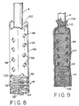
- a rigid cylinder 94 that is similar to the rigid cylinder 64 of Fig. 5 rests on the top disc 36 of the lower distributor screen 14. It has apertures 96 with inwardly extending triangular slots 98 around its outer edges, notches 100 at its upper end and notches 102 at its lower end.
- the slots 98 serve the same purpose as slots 65 of Fig. 5A, to prevent the sieve material at sieve bag 114 (see Fig. 10) from obstructing the associated aperture 96.
- Fig. 9 is the same as Fig. 8 except that a mesh bag 104 having a bottom 106 and an open end 108 is slipped over the sieve screen 14 and the rigid cylinder 94.
- a band 110 binds the open end 108 of the mesh bag 104 to the pipe 4
- a band 112 binds the mesh bag 104 to the lower portion of the rigid cylinder 94 and a band 112 binds the lower end. of the mesh bag 104 to the distributor screen 14.
- Fig. 10 is the same as Fig. 9 except that a sieve bag 114 has been placed around the mesh bag 104, but the latter can be seen through the sieve bag.
- the open end 116 of the sieve bag 114 is bound by bands 118 and 120 to the pipe 4.
- the ends of the band 120 extend outwardly from the riser pipe 4.
- a band 122 that has one end secured to the riser pipe 4 also extends outwardly therefrom.
- an important feature of this sieve bag is that its mesh size is only sufficiently fine to prevent the passage of ion exchange resin beads (for example, U.S. Standard Sieve Size No. 70).
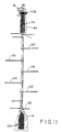
- Fig. 11 shows the entire screening assembly that is to be inserted into a ion exchange vessel 2 except for what is inside the mesh sleeve 74 and the mesh bag 104 and additional outwardly extending bands 124, 126, 128, and 130.
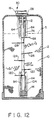
- Fig. 12 is a cross section of an ion exchange column with the assembly of Fig. 11 mounted therein for use.
- the top portion includes the modified distributor screen 12, the rigid cylinder 64, the mesh sleeve 74, and the sieve sleeve 84.
- the bottom portion includes the modified distributor screen 14, the rigid cylinder 94, the mesh bag 104 and the sieve bag 114.
- bands or protrusions 88, 120, 122, 124, 126, and 128 that extend outwardly from the riser pipe 4 into the resin 10. The bands or protrusions prevent the resin 10 from rising as a solid cake during backflow operation and blinding or blocking the upper screening mechanism 64, 74, and 84.
- the bands are constructed so as to resist bending in a vertical direction but to be flexible in an horizontal direction as previously noted.
- the bands as previously described, cause fissures in the rigid cake of resin beads 10 that facilitate fluidization of the resin beads 10, thereby preventing lifting of resin bead bed as a single unit.
- the port 30 is not visible in this view but is indicated as being behind the port 16.
- the advantageous operation of the invention is as follows.
- paint solution flows into the port 16.
- Part of the solution passes through the distributor screen 12, the mesh sleeve 74 and the sieve sleeve 84 into the top of the vessel 2, and part of the solution also flows through a flow path including the rigid cylinder 64, and portions of the mesh sleeve 74 and sieve sleeve 84.
- part of the solution flows through the sieve bag 114, the mesh bag 104 and the modified distributor screen 14 to the riser pipe 4, and another part also flows through the rigid cylinder 94 to the riser pipe 4 and the port 30.
- the sieve sleeve 84 is flexible rather than rigid, as is the unmodified distributor screen 12, any aggregated resin beads-latex-pigment become dislodged from the screen surface as the screen flexes.
- the material for the sieve sleeve 84 of Fig. 7, and the sieve bag 114 of Fig. 10 can be made with heavy material to be sufficiently rigid/flexible to retain their intended shapes without using other means, and to provide a self cleaning feature.
Landscapes
- Chemical & Material Sciences (AREA)
- Organic Chemistry (AREA)
- Chemical Kinetics & Catalysis (AREA)
- Life Sciences & Earth Sciences (AREA)
- Hydrology & Water Resources (AREA)
- Engineering & Computer Science (AREA)
- Environmental & Geological Engineering (AREA)
- Water Supply & Treatment (AREA)
- Devices And Processes Conducted In The Presence Of Fluids And Solid Particles (AREA)
- Filtration Of Liquid (AREA)
- Manufacture Of Macromolecular Shaped Articles (AREA)
- Treatment Of Water By Ion Exchange (AREA)
Description
Claims (11)
- Apparatus for use in an ion exchange unit comprising:a riser pipe (4);a rigid cylinder (64) coaxial with said riser pipe (4);a plurality of apertures (66) extending through said cylinder (64);a mesh cylinder (74) coaxial with and outside said rigid cylinder (64);means (76) for securing one end of the mesh cylinder (74) to the riser pipe (4) at a point adjacent one end of the rigid cylinder;means (82) for securing the other end of the mesh cylinder (74) to the other end of the rigid cylinder (64);a flexible sieve sleeve (84) surrounding said mesh cylinder (74);means (86) for securing one end of the sieve sleeve (84) to the riser pipe (4) at a point adjacent said one end of the rigid cylinder;means (88, 90, 92) for securing the other end of the sieve sleeve (84) to said riser pipe (4) at a point adjacent the other end of said rigid cylinder (64); andmeans for conducting fluid through a space between the riser pipe (4) and the rigid cylinder (64).
- Apparatus as claimed in claim 1, which further comprises:a second rigid cylinder (94) coaxial with and adjacent the other end of said riser pipe (4) having an inner diameter larger that the outer diameter of the riser pipe (4);a flexible mesh bag (104) covering the second rigid cylinder (94);means (110, 112) for securing said flexible mesh (104) bag to the second rigid cylinder (94);a flexible sieve bag (114) enclosing the second mesh sleeve (104), said bag having a closed end adjacent the other end of the riser pipe and an open end (116); andmeans (118, 120) for securing the open end of the bag (116) to the riser pipe (4).
- Apparatus as claimed in claim 2 which further comprises a protrusion attached to the riser pipe (4) at a point between the sieve sleeve (84) and the sieve bag (114), said protrusion extending outwardly from the pipe (4).
- Apparatus as claimed in claim 2 or claim 3 which further comprises a plurality of protrusions (130, 128, 126, 124, 122, 120) attached to the riser pipe (4) at points between the sieve sleeve (84) and the sieve bag (114), said protrusions extending outwardly from the riser pipe (4).
- Apparatus as claimed in any of the preceding claims, wherein slots (65) are formed in the outer edges of the apertures (66) in the rigid cylinder (64).
- Apparatus as claimed in any of claims 2 to 5, wherein slots (98) are formed in the outer edges of the apertures (96) in the second rigid cylinder (94).
- Apparatus as claimed in any of the preceding claims, which further comprises notches (70, 100, 102) in the ends of said rigid cylinders (64, 94).
- Apparatus as claimed in any of the preceding, claims, wherein the sieve sleeve (84) and / or the sieve bag (114) comprise material heavy enough to be sufficiently rigid / flexible, so as to retain the intended shapes of the sieve sleeve (84) and the sieve bag (114) and to provide each with a self cleaning feature.
- Apparatus as claimed in any of claims 2 to 8, wherein the material of said sieve sleeve (84), and sieve bag (114) has an aperture size suitable to prevent the passage there through of ion exchange beads (10) contained within the ion exchange unit.
- Apparatus as claimed in any of the preceding claims, further comprising:means for providing fluid communication between a first port (16) and the space between the riser pipe (4) and the rigid cylinder (64); anda second port (30) coupled to one end of the riser pipe (4), whereby fluid passing between the first and second ports passes through the cylinder, the mesh material and the sieve.
- Apparatus as claimed in claim 10, wherein the sieve comprises material having an aperture size that prevents the passage of ion exchange resin beads therethrough, the beads being contained within an associated ion exchange column.
Applications Claiming Priority (3)
| Application Number | Priority Date | Filing Date | Title |
|---|---|---|---|
| US08/302,156 US5545319A (en) | 1994-09-08 | 1994-09-08 | Sieve system for an ion exchange column |
| US302156 | 1994-09-08 | ||
| PCT/US1995/010729 WO1996007462A1 (en) | 1994-09-08 | 1995-08-29 | Sieve system for an ion exchange column |
Publications (3)
| Publication Number | Publication Date |
|---|---|
| EP0779830A1 EP0779830A1 (en) | 1997-06-25 |
| EP0779830A4 EP0779830A4 (en) | 1998-05-06 |
| EP0779830B1 true EP0779830B1 (en) | 2002-01-16 |
Family
ID=23166502
Family Applications (1)
| Application Number | Title | Priority Date | Filing Date |
|---|---|---|---|
| EP95930259A Expired - Lifetime EP0779830B1 (en) | 1994-09-08 | 1995-08-29 | Sieve system for an ion exchange column |
Country Status (8)
| Country | Link |
|---|---|
| US (1) | US5545319A (en) |
| EP (1) | EP0779830B1 (en) |
| JP (1) | JPH08187437A (en) |
| AU (1) | AU3371095A (en) |
| CA (1) | CA2197464A1 (en) |
| DE (1) | DE69525055T2 (en) |
| ES (1) | ES2168381T3 (en) |
| WO (1) | WO1996007462A1 (en) |
Families Citing this family (18)
| Publication number | Priority date | Publication date | Assignee | Title |
|---|---|---|---|---|
| US6032821A (en) * | 1998-06-03 | 2000-03-07 | United States Filter Corporation | Center opening treatment tank |
| US6183637B1 (en) | 1998-07-23 | 2001-02-06 | Seh America, Inc. | Resin trap device for use in ultrapure water systems and method of purifying water using same |
| DE29907957U1 (en) * | 1999-05-04 | 1999-08-12 | Schäfer Werke GmbH, 57290 Neunkirchen | container |
| GB0011989D0 (en) * | 2000-05-19 | 2000-07-05 | Shakesby & Sons Ltd | Improvements in and relating to water softeners |
| US6730229B1 (en) * | 2000-11-10 | 2004-05-04 | Awts, Inc. | Filter screen nozzle and system for fluid processing |
| US20060163118A1 (en) * | 2005-01-26 | 2006-07-27 | Eastman Kodak Company | Particulate separation processes and apparatus |
| US8071959B2 (en) * | 2005-12-21 | 2011-12-06 | Ottawa Heart Institute Research Corp. | Rubidium generator for cardiac perfusion imaging and method of making and maintaining same |
| US20080083623A1 (en) * | 2006-10-04 | 2008-04-10 | Golden Josh H | Method and apparatus for treatment of plating solutions |
| JP4921426B2 (en) * | 2008-06-30 | 2012-04-25 | イースタン技研株式会社 | Fresh water rust prevention treatment equipment |
| JP2010099648A (en) * | 2008-09-26 | 2010-05-06 | Ryoden Koki Engineering Kk | Water purifier |
| DE102009035401A1 (en) * | 2009-07-30 | 2011-02-03 | Hydac Filter Systems Gmbh | filter means |
| US8876017B2 (en) | 2010-08-11 | 2014-11-04 | Bilfinger Water Technologies, Inc. | Variable flow screen nozzle |
| US11821545B1 (en) * | 2018-01-12 | 2023-11-21 | Enpress Llc | Convertible head for deionization vessels |
| US11471794B2 (en) | 2019-02-11 | 2022-10-18 | Watts Regulator Co. | Filter cartridge for a whole house water filtering system |
| US11333264B2 (en) | 2019-02-11 | 2022-05-17 | Watts Regulator Co. | Manifold assembly for a water filter system |
| US11725781B2 (en) | 2019-02-11 | 2023-08-15 | Watts Regulator Co. | Pressure relief cover assembly |
| US12320087B2 (en) * | 2021-07-14 | 2025-06-03 | The United States Of America As Represented By The Secretary Of Agriculture | Submerged liquid intake strainers |
| ES3052443T3 (en) * | 2022-01-25 | 2026-01-07 | Foresa Tech S L U | Ion exchange method for deacidification of an aqueous formaldehyde solution, and an installation for performing such method |
Family Cites Families (13)
| Publication number | Priority date | Publication date | Assignee | Title |
|---|---|---|---|---|
| US171056A (en) * | 1875-12-14 | Improvement in apparatus for filtering liquids | ||
| US2725144A (en) * | 1953-05-14 | 1955-11-29 | Equipment Dev Co Inc | Filter element |
| US2785109A (en) * | 1955-03-14 | 1957-03-12 | William C Schwalge | Oil reclaimer |
| US3220552A (en) * | 1961-03-30 | 1965-11-30 | Culligan Inc | Automatic regeneration of treating material |
| US3174623A (en) * | 1961-04-06 | 1965-03-23 | Charles H Sloan | Water softener |
| US3263813A (en) * | 1965-09-23 | 1966-08-02 | Paul A Keller | Filtration apparatus |
| FR1547456A (en) * | 1967-06-14 | 1968-11-29 | Grenobloise Etude Appl | Treatment unit for water or aqueous solutions |
| US3685657A (en) * | 1971-03-16 | 1972-08-22 | Bruce H Hunter | Filter underdrain assembly and method of producing same |
| US4094790A (en) * | 1976-11-11 | 1978-06-13 | Industrial Filter & Pump Mfg. Co. | Distributor collector assembly |
| DE3113622C1 (en) * | 1981-04-03 | 1982-12-09 | Willy 7151 Affalterbach Herrmann | Filter device for water removal and / or full desalination of water |
| JPS5950367B2 (en) * | 1982-03-12 | 1984-12-07 | タカラ工業株式会社 | filtration device |
| US4773998A (en) * | 1987-03-17 | 1988-09-27 | Heinrich Elmer G | Water filter |
| US5089108A (en) * | 1990-06-25 | 1992-02-18 | Small Robert M | Strainer |
-
1994
- 1994-09-08 US US08/302,156 patent/US5545319A/en not_active Expired - Fee Related
-
1995
- 1995-08-29 DE DE69525055T patent/DE69525055T2/en not_active Expired - Fee Related
- 1995-08-29 CA CA002197464A patent/CA2197464A1/en not_active Abandoned
- 1995-08-29 AU AU33710/95A patent/AU3371095A/en not_active Abandoned
- 1995-08-29 ES ES95930259T patent/ES2168381T3/en not_active Expired - Lifetime
- 1995-08-29 EP EP95930259A patent/EP0779830B1/en not_active Expired - Lifetime
- 1995-08-29 WO PCT/US1995/010729 patent/WO1996007462A1/en not_active Ceased
- 1995-09-07 JP JP7230515A patent/JPH08187437A/en active Pending
Also Published As
| Publication number | Publication date |
|---|---|
| ES2168381T3 (en) | 2002-06-16 |
| US5545319A (en) | 1996-08-13 |
| WO1996007462A1 (en) | 1996-03-14 |
| DE69525055T2 (en) | 2002-08-22 |
| EP0779830A1 (en) | 1997-06-25 |
| DE69525055D1 (en) | 2002-02-21 |
| EP0779830A4 (en) | 1998-05-06 |
| AU3371095A (en) | 1996-03-27 |
| CA2197464A1 (en) | 1996-03-14 |
| JPH08187437A (en) | 1996-07-23 |
Similar Documents
| Publication | Publication Date | Title |
|---|---|---|
| US5545319A (en) | Sieve system for an ion exchange column | |
| US6254772B1 (en) | Backwashable filtration system | |
| RU2455049C2 (en) | Method and device for cleaning filters with loose packing | |
| DE69928348T2 (en) | Water treatment device with regeneration of the treatment medium contained therein | |
| US4826609A (en) | Filter media for filter systems | |
| DE60314503T2 (en) | FILTER DEVICE | |
| JPH02503163A (en) | Filter device and method | |
| DE112014006168T5 (en) | Filter element and filter device | |
| EP1185348B1 (en) | Filter underdrain | |
| DE3915354A1 (en) | VIBRATION SCREEN WITH FILTER AND METHOD FOR CLEANING THE FILTER | |
| US2600458A (en) | Upflow pressure diatomite filtering apparatus | |
| EP3908391B1 (en) | Filter system for purifying a gas flow charged with particles, and arrangement for purifying a gas flow, charged with particles, of a fluidising apparatus by means of a filter system | |
| GB2233575A (en) | Underdrain strainer assembly | |
| EP0742038B1 (en) | Filter for heating installation | |
| US6576146B2 (en) | Filtration element employing improved backwash feature and method of utilizing same | |
| JPH05253497A (en) | Column for use in ion exchange process | |
| DE1943999B2 (en) | DEVICE FOR FILTERING A LIQUID | |
| CN209378539U (en) | A kind of filtering tank equipped with water distributor | |
| DE20000648U1 (en) | Device for fastening and sealing round, hanging, vertically aligned filter bags with support baskets in a horizontally arranged hose mounting plate | |
| EP0305606B1 (en) | Back-wash filter assembly | |
| DE10152047B4 (en) | Apparatus and method for purifying wastewater | |
| WO1991013670A1 (en) | A liquid distributor for use in granular filter beds | |
| KR200227931Y1 (en) | Strainer block improved on backwashing ability | |
| CN215609741U (en) | Basket filter is used in antirust oil production convenient to change filter screen | |
| KR200225090Y1 (en) | Strainer block nozzle for sand filters |
Legal Events
| Date | Code | Title | Description |
|---|---|---|---|
| PUAI | Public reference made under article 153(3) epc to a published international application that has entered the european phase |
Free format text: ORIGINAL CODE: 0009012 |
|
| 17P | Request for examination filed |
Effective date: 19970401 |
|
| AK | Designated contracting states |
Kind code of ref document: A1 Designated state(s): DE ES FR GB |
|
| A4 | Supplementary search report drawn up and despatched |
Effective date: 19980319 |
|
| AK | Designated contracting states |
Kind code of ref document: A4 Designated state(s): DE ES FR GB |
|
| 17Q | First examination report despatched |
Effective date: 20000705 |
|
| GRAG | Despatch of communication of intention to grant |
Free format text: ORIGINAL CODE: EPIDOS AGRA |
|
| GRAG | Despatch of communication of intention to grant |
Free format text: ORIGINAL CODE: EPIDOS AGRA |
|
| GRAH | Despatch of communication of intention to grant a patent |
Free format text: ORIGINAL CODE: EPIDOS IGRA |
|
| GRAG | Despatch of communication of intention to grant |
Free format text: ORIGINAL CODE: EPIDOS AGRA |
|
| GRAH | Despatch of communication of intention to grant a patent |
Free format text: ORIGINAL CODE: EPIDOS IGRA |
|
| GRAH | Despatch of communication of intention to grant a patent |
Free format text: ORIGINAL CODE: EPIDOS IGRA |
|
| GRAA | (expected) grant |
Free format text: ORIGINAL CODE: 0009210 |
|
| REG | Reference to a national code |
Ref country code: GB Ref legal event code: IF02 |
|
| AK | Designated contracting states |
Kind code of ref document: B1 Designated state(s): DE ES FR GB |
|
| REF | Corresponds to: |
Ref document number: 69525055 Country of ref document: DE Date of ref document: 20020221 |
|
| REG | Reference to a national code |
Ref country code: ES Ref legal event code: FG2A Ref document number: 2168381 Country of ref document: ES Kind code of ref document: T3 |
|
| ET | Fr: translation filed | ||
| PG25 | Lapsed in a contracting state [announced via postgrant information from national office to epo] |
Ref country code: GB Free format text: LAPSE BECAUSE OF NON-PAYMENT OF DUE FEES Effective date: 20020829 |
|
| PG25 | Lapsed in a contracting state [announced via postgrant information from national office to epo] |
Ref country code: ES Free format text: LAPSE BECAUSE OF NON-PAYMENT OF DUE FEES Effective date: 20020830 |
|
| PLBE | No opposition filed within time limit |
Free format text: ORIGINAL CODE: 0009261 |
|
| STAA | Information on the status of an ep patent application or granted ep patent |
Free format text: STATUS: NO OPPOSITION FILED WITHIN TIME LIMIT |
|
| 26N | No opposition filed | ||
| PG25 | Lapsed in a contracting state [announced via postgrant information from national office to epo] |
Ref country code: DE Free format text: LAPSE BECAUSE OF NON-PAYMENT OF DUE FEES Effective date: 20030301 |
|
| GBPC | Gb: european patent ceased through non-payment of renewal fee |
Effective date: 20020829 |
|
| PG25 | Lapsed in a contracting state [announced via postgrant information from national office to epo] |
Ref country code: FR Free format text: LAPSE BECAUSE OF NON-PAYMENT OF DUE FEES Effective date: 20030430 |
|
| REG | Reference to a national code |
Ref country code: FR Ref legal event code: ST |
|
| REG | Reference to a national code |
Ref country code: ES Ref legal event code: FD2A Effective date: 20030912 |