EP0778404B1 - Throttle valve actuator with non-linear to linear cam operation - Google Patents
Throttle valve actuator with non-linear to linear cam operation Download PDFInfo
- Publication number
- EP0778404B1 EP0778404B1 EP96118240A EP96118240A EP0778404B1 EP 0778404 B1 EP0778404 B1 EP 0778404B1 EP 96118240 A EP96118240 A EP 96118240A EP 96118240 A EP96118240 A EP 96118240A EP 0778404 B1 EP0778404 B1 EP 0778404B1
- Authority
- EP
- European Patent Office
- Prior art keywords
- shaft
- cable
- rotation
- pliant
- throttle valve
- Prior art date
- Legal status (The legal status is an assumption and is not a legal conclusion. Google has not performed a legal analysis and makes no representation as to the accuracy of the status listed.)
- Expired - Lifetime
Links
Images


Classifications
-
- F—MECHANICAL ENGINEERING; LIGHTING; HEATING; WEAPONS; BLASTING
- F02—COMBUSTION ENGINES; HOT-GAS OR COMBUSTION-PRODUCT ENGINE PLANTS
- F02D—CONTROLLING COMBUSTION ENGINES
- F02D9/00—Controlling engines by throttling air or fuel-and-air induction conduits or exhaust conduits
- F02D9/02—Controlling engines by throttling air or fuel-and-air induction conduits or exhaust conduits concerning induction conduits
- F02D2009/0201—Arrangements; Control features; Details thereof
- F02D2009/0261—Arrangements; Control features; Details thereof having a specially shaped transmission member, e.g. a cam, specially toothed gears, with a clutch
Definitions
- the invention relates to a throttle valve actuator which is mounted on a valve shaft of a throttle valve, and more particularly, to a cam for modifying an effective moment arm of force being transmitted between a pliant cable and the throttle valve actuator so that the moment arm rapidly decreases during a first angular portion of rotation about the throttle shaft from the closed position (See e.g. US-A- 5 165 298; DE-A-3 403 760).
- a throttle body defines an aperture extending therethrough to deliver a charge to a compression chamber in communication with the aperture.
- a valve typically is mounted on a shaft for rotation within the aperture of the throttle body to control the internal combustion engine. Rotation of the throttle shaft causes variation in the flow area around the valve member.
- a crank arm is typically connected to the shaft for driving the valve member in rotation between a closed position and an open position.
- a throttle cable is coupled at one end to the crank arm and at an opposite end to an accelerator pedal. Displacement of the accelerator pedal causes rotation of the crank arm and throttle shaft thereby varying the flow area around the throttle valve.
- the crank arm is mounted typically on an end of the throttle shaft outside of the throttle body so that the crank arm can rotate between a closed position wherein the flow area around the valve is minimum and an open position where the flow area is increased.
- a tensile force is applied to the pliant cable connected to the crank arm by displacement of the accelerator pedal, the force causes the throttle valve to rotate away from the closed position toward an open position.
- a return spring is typically connected to the throttle shaft, so that when tensile force through the pliant cable is decreased, the return spring urges the throttle valve to rotate toward the closed position. It is also known to provide connections to the throttle shaft, typically on the crank arm, for cruise control systems and/or automatic transmission shifting control systems.
- a throttle valve actuator is provided as defined in claim 1.
- a cam is connected to the crank arm for modifying an effective moment arm of force being transmitted between the pliant cable and the crank arm, such that the moment arm rapidly decreases during a first angular portion of rotation about the throttle shaft from the closed position and substantially stabilizes during a second angular portion of rotation about the throttle shaft to the open position.
- the first angular portion of rotation about the throttle shaft is preferably in a range of between approximately 30° and approximately 40° inclusive.
- the second angular portion of rotation about the throttle shaft is preferably in a range of between approximately 45° and approximately 55° inclusive.
- the first or closed position of the throttle valve is generally disposed at an angular position corresponding to 0° while the second or open position of the throttle shaft is generally disposed at an angular position corresponding to 85°.
- the cam can be spaced from the anchor point of the pliant cable on the crank arm.
- the cam can also be selectively engageable with the pliant cable during the first angular portion of rotation about the throttle shaft and disengaged from the pliant cable during the second angular portion of rotation about the throttle shaft.
- the cam preferably has a notch or trough-shaped cable guide formed therein for receiving the pliant cable when in at least the closed position of the throttle valve.
- the notch extends along only a portion of the length of the pliant cable and is spaced from the anchor point of the pliant cable on the crank arm.
- the notch or cable track in the cam can include a trough-shaped guide having a bottom extending along a portion of the longitudinal length of the pliant cable with one end preferably spaced from the anchor point, or alternatively adjacent to the cable connection to the crank arm, and a pair of walls extending outwardly from the bottom of the cable guide.
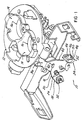
- a throttle valve actuator 10 is illustrated in Figures 1-6.
- the present invention is adapted for use on a conventional internal combustion engine having throttle body means 12 for defining at least one passageway or aperture 14 extending therethrough to deliver a charge to a combustion chamber in communication with the passageway or aperture 14.
- Valve means 16 is mounted on a shaft 18 for rotating movement within the aperture 14 of the throttle body means 12 to control the internal combustion engine.
- Crank arm means 20 is connected to the shaft 18 for driving the valve means 16 in rotation between a first or closed position and a second or open position.
- Pliant cable means 22 is connected to the crank arm means 20 at an anchor point 24 adjacent one end 26 of the pliant cable means 22.
- the pliant cable means 22 transmits a force to the crank arm means 20 to control rotation of the valve means 16.
- the other end of the pliant cable means 22 is typically connected to an operator actuated device, such as a foot operated pedal, or hand operated lever, as is conventional.
- the throttle body means may define one or more passages or apertures 14 extending therethrough, and the valve means 16 may include one or more valves mounted on the shaft 18 for rotation therewith in response to movement of the crank arm means 20 and pliant cable means 22.
- Spring means 28 biases the crank arm means 20, connected shaft 18 and valve means 16 to a first position, generally corresponding to the closed position.
- the crank arm means 20 may also include anchor points 30 and 32 for cruise control system connection and automatic transmission shift control system connection to the crank arm means 20 as is also conventional.
- cam means 34 is connected to the crank arm means 20 for modifying an effective moment arm of force being transmitted between the pliant cable means 22 and the crank arm means 20, such that the moment arm rapidly decreases during a first angular portion of rotation about the shaft 18 from the first or closed position and the moment arm substantially stabilizes during a second angular portion of rotation about the shaft 18 to the second or open position.
- the cam means 34 lessens the sensitivity of the throttle valve actuator 10 adjacent the idle position so that it is not as responsive to movement of the pliant cable means 22 through approximately the first 30° to 40° of rotational travel of the crank arm means 20 about the shaft 18.
- the pliant cable means 22 has approximately 11 ⁇ 2 inches of travel between the idle or first position and the wide open or second position.
- the entire rotational angular movement of the crank arm means 20, shaft 18 and valve means 16 about the longitudinal axis of the shaft 18 is approximately 85° between the first and second positions.
- a conventional ball stud connection to the valve actuator is illustrated as curve 100.
- the standard ball stud connection was overly sensitive in the first angular portion of rotation about the longitudinal axis of the shaft 18 generally corresponding to movement between the 0° position and approximately the 30° or the 40° position of angle as illustrated in the graph depicted in Figure 10.
- a conventional constant radius connection to the throttle valve actuator is illustrated in curve or line 102 of the graph. While this improved on the sensitivity during the first angular portion of rotation over the ball stud connection curve 100, it still was overly sensitive in the first angular portion of rotation between the 0° position and approximately the 30° position or approximately the 40° position of angular rotation about the longitudinal axis of shaft 18.
- a conventional non-linear cam connection has been provided to the throttle valve actuator as illustrated in curve 104.
- the non-linear cam connection curve 104 proved to provide adequate reduction in the sensitivity of the throttle valve actuator 10 through the first angular portion of rotation about the longitudinal axis of shaft 18, but proved unsatisfactory in the second angular portion of rotation about the longitudinal axis of the shaft 18 from approximately the 30° position or the 40° position of rotation to the second position at approximately the 85° position of rotation as illustrated in the graph of Figure 10.
- the continued steep slope of the moment arm with respect to the angle as illustrated in Figure 10 for the non-linear cam connection curve in the second angular portion of rotation resulted in an undesirable increase in the amount of force required to maintain the throttle valve actuator 10 in the wide open or second position.
- cam means 34 such as a mini cam connection was provided as illustrated in curve 106.
- cam means 34 provides a rapidly decreasing moment arm during the first angular portion of rotation about the longitudinal axis of the shaft 18, while providing a generally, substantially constant moment arm during the second angular portion of rotation about the longitudinal axis of the shaft 18.
- the mini cam connection curve 106 provides the desirable characteristic of lessening the sensitivity of the pedal actuator adjacent the idle position to reduce the possibility of lurching of the vehicle in response to small pedal movements since this is considered undesirable, while reducing the amount of pedal force required to maintain the throttle valve actuator at the full open or second position.
- the throttle valve actuator 10 is shown in the first or closed position with the cam means 34 engaging with the pliant cable means 32.
- sufficient force has been applied through the pliant cable means 22 to rotate the crank arm means 20, shaft 18 and valve means 16 through a first angular portion of rotation about the longitudinal axis of the shaft 18 to a transition point between the first and second angular portions of rotation generally corresponding to an angular position in a range of between approximately 30° and approximately 40° inclusive, where the cam means 34 disengages from the pliant cable means 22 and further force applied by the pliant cable means 22 acts directly on the cable anchor point 24 of the crank arm means 20.
- the crank arm means 20 can include a first longitudinally extending projection 36 with respect to the longitudinal axis of the shaft 18 for engagement with one end of the spring means 28 for biasing the crank arm means 20 to the first position.
- a second longitudinally extending projection 38 can be provided for supporting the automatic transmission shift control connection anchor point 32.
- the first and second projections, 36 and 38 respectively, extend outwardly from a generally planar member 40 of the crank arm means 20.
- the planar member 40 is generally disposed perpendicular to the longitudinal axis of the shaft 18.
- the planar member 40 supports the cable anchor point 24 and cruise control system connection anchor point 30.
- the planar member 40 also includes aperture 42 for receiving an end of the shaft 18 for rotation therewith.
- the cam means 34 is connected to the planar member 40 and is generally disposed along the path of the longitudinal axis of the pliant cable means 22, so that the cam means 34 engages with the pliant cable means 22 during the first angular portion of rotation about the longitudinal axis of the shaft 18.
- the cam means 34 can preferably include a mini cam 44 connected to the crank arm means 20 spaced from the anchor point 24.
- the mini cam 44 includes a cam surface 46 engageable with the pliant cable means between the first position and the transition point while rotating through the first angular portion of rotation of the crank arm means 20 about the longitudinal axis of the shaft 18.
- the mini cam 44 modifies the effective moment arm acting on the crank arm means 20 through the pliant cable means 22 while rotating through the first angular portion of rotation about the longitudinal axis of the shaft 18.
- the cam surface 44 disengages from the pliant cable means 22 and the force of the pliant cable means 22 acts directly on the anchor point 24 to rotate the crank arm means 20 about the longitudinal axis of the shaft 18 through the second angular portion of rotation.
- This configuration provides the desirable operating characteristic curve 106 as illustrated in Figure 10.
- the cam 46 can be spaced from the anchor point 24 of the pliant cable 22 on the crank arm 20.
- the cam 46 can also be selectively engageable with the pliant cable 22 during the first angular portion of rotation about the throttle shaft 18 and disengaged from the pliant cable 22 during the second angular portion of rotation about the throttle shaft 18.
- the cam 46 preferably has a notch or trough-shaped cable guide 48 formed therein for receiving the pliant cable 22 when in at least the closed position of the throttle valve 16.
- the notch 48 extends along only a portion of the length of the pliant cable 22 and is spaced from the anchor point 24 of the pliant cable 22 on the crank arm 20.
- the notch or cable track 48 in the cam 46 can include a trough-shaped guide 48 having a bottom 46 extending along a portion of the longitudinal length of the pliant cable 22 with one end preferably spaced from the anchor point, or alternatively adjacent to the cable connection to the crank arm 20, and a pair of walls 50, 52 extending outwardly from the bottom of the cable guide 48.
- the cam means 34 can also be provided as illustrated in Figures 7-9.
- the throttle valve actuator 10 is shown in the closed or first position with the cam surface 46 selectively engageable with the pliant cable means 22 during the first angular portion of rotation about the longitudinal axis of shaft 18 and disengaged from the pliant cable means 22 during the second angular portion or rotation about the longitudinal axis of the shaft 18.
- the cam surface 46 extends to a position adjacent the anchor point 24 of the pliant cable means 22.
- the application of force through the pliant cable means 22 to the crank arm means 20 causes rotation about the longitudinal axis of shaft 18 to a transitional point generally corresponding to an angular position in a range between approximately 30° and approximately 40° inclusive, where the pliant cable means 22 disengages from the cam surface 46 during further rotation in the same direction.
- the portion of the cam surface 46 spaced from the anchor point 24 provides a first angular portion of rotation about the longitudinal axis of the shaft 18 where the moment arm rapidly decreases between the positions shown in Figure 7 and Figure 8.
- the pliant cable means 22 disengages from the cam surface 46 disposed adjacent to the anchor point 24 when rotating passed the position illustrated in Figure 8 to the full open or second position illustrated in Figure 9.
- This configuration provides a second angular portion of rotation about the longitudinal axis of the shaft 18 to the open or second position where the moment arm of force is generally or substantially stabilized to a relatively constant value as illustrated in curve 106 of Figure 10.
- Curve 106 in Figure 10 illustrates a slight increase in the moment arm during a first part of the second angular portion of rotation about the longitudinal axis of the shaft 18 generally between the transition point and approximately the 60° angle position. Curve 106 further illustrates a slight decrease in the moment arm during a second part of the second angular portion of rotation about the longitudinal axis of shaft 18 corresponding generally to movement between approximately 60° and the second or closed position at approximately 85°.
Landscapes
- Engineering & Computer Science (AREA)
- Chemical & Material Sciences (AREA)
- Combustion & Propulsion (AREA)
- Mechanical Engineering (AREA)
- General Engineering & Computer Science (AREA)
- Control Of Throttle Valves Provided In The Intake System Or In The Exhaust System (AREA)
Description
- The invention relates to a throttle valve actuator which is mounted on a valve shaft of a throttle valve, and more particularly, to a cam for modifying an effective moment arm of force being transmitted between a pliant cable and the throttle valve actuator so that the moment arm rapidly decreases during a first angular portion of rotation about the throttle shaft from the closed position (See e.g. US-A- 5 165 298; DE-A-3 403 760).
- In an internal combustion engine, a throttle body defines an aperture extending therethrough to deliver a charge to a compression chamber in communication with the aperture. A valve typically is mounted on a shaft for rotation within the aperture of the throttle body to control the internal combustion engine. Rotation of the throttle shaft causes variation in the flow area around the valve member. A crank arm is typically connected to the shaft for driving the valve member in rotation between a closed position and an open position. A throttle cable is coupled at one end to the crank arm and at an opposite end to an accelerator pedal. Displacement of the accelerator pedal causes rotation of the crank arm and throttle shaft thereby varying the flow area around the throttle valve. The crank arm is mounted typically on an end of the throttle shaft outside of the throttle body so that the crank arm can rotate between a closed position wherein the flow area around the valve is minimum and an open position where the flow area is increased. When a tensile force is applied to the pliant cable connected to the crank arm by displacement of the accelerator pedal, the force causes the throttle valve to rotate away from the closed position toward an open position. A return spring is typically connected to the throttle shaft, so that when tensile force through the pliant cable is decreased, the return spring urges the throttle valve to rotate toward the closed position. It is also known to provide connections to the throttle shaft, typically on the crank arm, for cruise control systems and/or automatic transmission shifting control systems.
- It is desirable in the present invention to provide a throttle valve actuator for modifying an effective moment arm of force being transmitted between the pliant cable and the crank arm, so that the moment arm rapidly decreases during a first angular portion of rotation about the throttle shaft from the closed position and substantially stabilizes during a second angular portion of rotation about the throttle shaft to the open position. This decreases the sensitivity of the accelerator pedal at low speeds to reduce the tendency of the engine to surge or be overly sensitive to initial depression of the accelerator pedal from the throttle closed position.
- According to the present invention, a throttle valve actuator is provided as defined in claim 1. A cam is connected to the crank arm for modifying an effective moment arm of force being transmitted between the pliant cable and the crank arm, such that the moment arm rapidly decreases during a first angular portion of rotation about the throttle shaft from the closed position and substantially stabilizes during a second angular portion of rotation about the throttle shaft to the open position.
- The first angular portion of rotation about the throttle shaft is preferably in a range of between approximately 30° and approximately 40° inclusive. The second angular portion of rotation about the throttle shaft is preferably in a range of between approximately 45° and approximately 55° inclusive. The first or closed position of the throttle valve is generally disposed at an angular position corresponding to 0° while the second or open position of the throttle shaft is generally disposed at an angular position corresponding to 85°.
- The cam can be spaced from the anchor point of the pliant cable on the crank arm. The cam can also be selectively engageable with the pliant cable during the first angular portion of rotation about the throttle shaft and disengaged from the pliant cable during the second angular portion of rotation about the throttle shaft. The cam preferably has a notch or trough-shaped cable guide formed therein for receiving the pliant cable when in at least the closed position of the throttle valve. In the preferred embodiment, the notch extends along only a portion of the length of the pliant cable and is spaced from the anchor point of the pliant cable on the crank arm. The notch or cable track in the cam can include a trough-shaped guide having a bottom extending along a portion of the longitudinal length of the pliant cable with one end preferably spaced from the anchor point, or alternatively adjacent to the cable connection to the crank arm, and a pair of walls extending outwardly from the bottom of the cable guide.
- Other objects, advantages and applications of the present invention will become apparent to those skilled in the art when the following description of the best mode contemplated for practicing the invention is read in conjunction with the accompanying drawings.
- The description herein makes reference to the accompanying drawings wherein like reference numerals refer to like parts throughout the several views, and wherein:
- Figure 1 is a perspective view of a throttle valve actuator according to the present invention mounted on a shaft rotatably connected to a throttle body supporting a throttle valve of an internal combustion engine with the pliant throttle cable not shown;
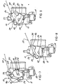
- Figure 2 is a side elevational view of the throttle valve actuator according to the present invention in a closed position;
- Figure 3 is a side elevational view of the throttle valve actuator according to the present invention in a partially open position corresponding to the transition point between a first angular portion of rotation about the throttle shaft with rapidly decreasing moment arm and a second angular portion of rotation about the throttle shaft with a generally constant moment arm;
- Figure 4 is a side elevational view of the throttle valve actuator according to the present invention in an open position;
- Figure 5 is a plan view of the throttle valve actuator according to the present invention;
- Figure 6 is a detailed cross-sectional view of the throttle valve actuator taken as shown in Figure 5;
- Figure 7 is a side elevational view of an alternative configuration for the throttle valve actuator according to the present invention in a closed position;
- Figure 8 is a side elevational view of the throttle valve actuator according to the present invention in a partially open position corresponding to a transition between a first angular portion of rotation about the throttle shaft where a moment arm rapidly decreases and a second angular portion of rotation about the throttle shaft where the moment arm remains generally constant;
- Figure 9 is a side elevational view of a throttle valve actuator according to the present invention in the open position; and
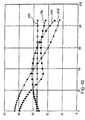
- Figure 10 is a graph illustrating moment arm in millimeters versus angle in degrees for the throttle valve actuator according to the present invention in comparison with three other known throttle valve actuator configurations.
-
- A
throttle valve actuator 10 according to the present invention is illustrated in Figures 1-6. The present invention is adapted for use on a conventional internal combustion engine having throttle body means 12 for defining at least one passageway oraperture 14 extending therethrough to deliver a charge to a combustion chamber in communication with the passageway oraperture 14. Valve means 16 is mounted on ashaft 18 for rotating movement within theaperture 14 of the throttle body means 12 to control the internal combustion engine. Crank arm means 20 is connected to theshaft 18 for driving the valve means 16 in rotation between a first or closed position and a second or open position. Pliant cable means 22 is connected to the crank arm means 20 at ananchor point 24 adjacent oneend 26 of the pliant cable means 22. The pliant cable means 22 transmits a force to the crank arm means 20 to control rotation of the valve means 16. The other end of the pliant cable means 22 is typically connected to an operator actuated device, such as a foot operated pedal, or hand operated lever, as is conventional. The throttle body means may define one or more passages orapertures 14 extending therethrough, and the valve means 16 may include one or more valves mounted on theshaft 18 for rotation therewith in response to movement of the crank arm means 20 and pliant cable means 22. Spring means 28 biases the crank arm means 20, connectedshaft 18 and valve means 16 to a first position, generally corresponding to the closed position. The crank arm means 20 may also includeanchor points - According to the present invention,
cam means 34 is connected to the crank arm means 20 for modifying an effective moment arm of force being transmitted between the pliant cable means 22 and the crank arm means 20, such that the moment arm rapidly decreases during a first angular portion of rotation about theshaft 18 from the first or closed position and the moment arm substantially stabilizes during a second angular portion of rotation about theshaft 18 to the second or open position. In the preferred configuration of the cam means 34 illustrated in Figures 1-6, the cam means 34 lessens the sensitivity of thethrottle valve actuator 10 adjacent the idle position so that it is not as responsive to movement of the pliant cable means 22 through approximately the first 30° to 40° of rotational travel of the crank arm means 20 about theshaft 18. Typically, the pliant cable means 22 has approximately 1½ inches of travel between the idle or first position and the wide open or second position. The entire rotational angular movement of the crank arm means 20,shaft 18 and valve means 16 about the longitudinal axis of theshaft 18 is approximately 85° between the first and second positions. - As best seen in Figure 10, a conventional ball stud connection to the valve actuator is illustrated as
curve 100. The standard ball stud connection was overly sensitive in the first angular portion of rotation about the longitudinal axis of theshaft 18 generally corresponding to movement between the 0° position and approximately the 30° or the 40° position of angle as illustrated in the graph depicted in Figure 10. A conventional constant radius connection to the throttle valve actuator is illustrated in curve orline 102 of the graph. While this improved on the sensitivity during the first angular portion of rotation over the ballstud connection curve 100, it still was overly sensitive in the first angular portion of rotation between the 0° position and approximately the 30° position or approximately the 40° position of angular rotation about the longitudinal axis ofshaft 18. A conventional non-linear cam connection has been provided to the throttle valve actuator as illustrated incurve 104. The non-linearcam connection curve 104 proved to provide adequate reduction in the sensitivity of thethrottle valve actuator 10 through the first angular portion of rotation about the longitudinal axis ofshaft 18, but proved unsatisfactory in the second angular portion of rotation about the longitudinal axis of theshaft 18 from approximately the 30° position or the 40° position of rotation to the second position at approximately the 85° position of rotation as illustrated in the graph of Figure 10. The continued steep slope of the moment arm with respect to the angle as illustrated in Figure 10 for the non-linear cam connection curve in the second angular portion of rotation resulted in an undesirable increase in the amount of force required to maintain thethrottle valve actuator 10 in the wide open or second position. It is therefore desirable in the present invention to reduce the pedal force required to maintain thethrottle valve actuator 10 at the full open or second position. Therefore, according to the present invention, cam means 34, such as a mini cam connection was provided as illustrated incurve 106. According to the present invention,cam means 34 provides a rapidly decreasing moment arm during the first angular portion of rotation about the longitudinal axis of theshaft 18, while providing a generally, substantially constant moment arm during the second angular portion of rotation about the longitudinal axis of theshaft 18. The minicam connection curve 106 provides the desirable characteristic of lessening the sensitivity of the pedal actuator adjacent the idle position to reduce the possibility of lurching of the vehicle in response to small pedal movements since this is considered undesirable, while reducing the amount of pedal force required to maintain the throttle valve actuator at the full open or second position. - Referring to Figure 2, the
throttle valve actuator 10 is shown in the first or closed position with the cam means 34 engaging with the pliant cable means 32. In Figure 3, sufficient force has been applied through the pliant cable means 22 to rotate the crank arm means 20,shaft 18 and valve means 16 through a first angular portion of rotation about the longitudinal axis of theshaft 18 to a transition point between the first and second angular portions of rotation generally corresponding to an angular position in a range of between approximately 30° and approximately 40° inclusive, where the cam means 34 disengages from the pliant cable means 22 and further force applied by the pliant cable means 22 acts directly on thecable anchor point 24 of the crank arm means 20. In Figure 4, sufficient force has been applied through the pliant cable means 22 to rotate the crank arm means 20,shaft 18 and valve means 16 to the second or wide open position, generally corresponding to an angular position of approximately 85° of rotation about the longitudinal axis of theshaft 18 with respect to the closed or first position illustrated in Figure 2 corresponding to an angular position of 0°. After release of the force acting through the pliant cable means 22, the spring means 28 biases the crank arm means 20 toward the first position as shown in Figure 2. - Referring now to Figures 5 and 6, the crank arm means 20 can include a first
longitudinally extending projection 36 with respect to the longitudinal axis of theshaft 18 for engagement with one end of the spring means 28 for biasing the crank arm means 20 to the first position. A second longitudinally extendingprojection 38 can be provided for supporting the automatic transmission shift controlconnection anchor point 32. The first and second projections, 36 and 38 respectively, extend outwardly from a generallyplanar member 40 of the crank arm means 20. Theplanar member 40 is generally disposed perpendicular to the longitudinal axis of theshaft 18. Theplanar member 40 supports thecable anchor point 24 and cruise control systemconnection anchor point 30. Theplanar member 40 also includesaperture 42 for receiving an end of theshaft 18 for rotation therewith. The cam means 34 is connected to theplanar member 40 and is generally disposed along the path of the longitudinal axis of the pliant cable means 22, so that the cam means 34 engages with the pliant cable means 22 during the first angular portion of rotation about the longitudinal axis of theshaft 18. - The cam means 34 can preferably include a
mini cam 44 connected to the crank arm means 20 spaced from theanchor point 24. Themini cam 44 includes acam surface 46 engageable with the pliant cable means between the first position and the transition point while rotating through the first angular portion of rotation of the crank arm means 20 about the longitudinal axis of theshaft 18. Themini cam 44 modifies the effective moment arm acting on the crank arm means 20 through the pliant cable means 22 while rotating through the first angular portion of rotation about the longitudinal axis of theshaft 18. After passing the transition point, preferably at an angular position in a range of between approximately 30° and approximately 40° inclusive, thecam surface 44 disengages from the pliant cable means 22 and the force of the pliant cable means 22 acts directly on theanchor point 24 to rotate the crank arm means 20 about the longitudinal axis of theshaft 18 through the second angular portion of rotation. This configuration provides the desirable operatingcharacteristic curve 106 as illustrated in Figure 10. - The
cam 46 can be spaced from theanchor point 24 of thepliant cable 22 on thecrank arm 20. Thecam 46 can also be selectively engageable with thepliant cable 22 during the first angular portion of rotation about thethrottle shaft 18 and disengaged from thepliant cable 22 during the second angular portion of rotation about thethrottle shaft 18. Thecam 46 preferably has a notch or trough-shapedcable guide 48 formed therein for receiving thepliant cable 22 when in at least the closed position of thethrottle valve 16. In the preferred embodiment, thenotch 48 extends along only a portion of the length of thepliant cable 22 and is spaced from theanchor point 24 of thepliant cable 22 on thecrank arm 20. The notch orcable track 48 in thecam 46 can include a trough-shapedguide 48 having a bottom 46 extending along a portion of the longitudinal length of thepliant cable 22 with one end preferably spaced from the anchor point, or alternatively adjacent to the cable connection to thecrank arm 20, and a pair ofwalls cable guide 48. - The cam means 34 can also be provided as illustrated in Figures 7-9. In Figure 7, the
throttle valve actuator 10 is shown in the closed or first position with thecam surface 46 selectively engageable with the pliant cable means 22 during the first angular portion of rotation about the longitudinal axis ofshaft 18 and disengaged from the pliant cable means 22 during the second angular portion or rotation about the longitudinal axis of theshaft 18. In this configuration, thecam surface 46 extends to a position adjacent theanchor point 24 of the pliant cable means 22. As illustrated in Figure 8, the application of force through the pliant cable means 22 to the crank arm means 20 causes rotation about the longitudinal axis ofshaft 18 to a transitional point generally corresponding to an angular position in a range between approximately 30° and approximately 40° inclusive, where the pliant cable means 22 disengages from thecam surface 46 during further rotation in the same direction. The portion of thecam surface 46 spaced from theanchor point 24 provides a first angular portion of rotation about the longitudinal axis of theshaft 18 where the moment arm rapidly decreases between the positions shown in Figure 7 and Figure 8. As shown in Figure 9, the pliant cable means 22 disengages from thecam surface 46 disposed adjacent to theanchor point 24 when rotating passed the position illustrated in Figure 8 to the full open or second position illustrated in Figure 9. This configuration provides a second angular portion of rotation about the longitudinal axis of theshaft 18 to the open or second position where the moment arm of force is generally or substantially stabilized to a relatively constant value as illustrated incurve 106 of Figure 10. -
Curve 106 in Figure 10 illustrates a slight increase in the moment arm during a first part of the second angular portion of rotation about the longitudinal axis of theshaft 18 generally between the transition point and approximately the 60° angle position.Curve 106 further illustrates a slight decrease in the moment arm during a second part of the second angular portion of rotation about the longitudinal axis ofshaft 18 corresponding generally to movement between approximately 60° and the second or closed position at approximately 85°.
Claims (11)
- Throttle valve actuator (10) for an internal combustion engine, including:the cam means (34) modifying the effective moment arm such that the moment arm rapidly decreases during a first angular portion of rotation about the shaft (18) from the closed position to a transition point characterized in that the effective moment arm substantially stabilizes during a second angular portion of rotation about the shaft from the transition point to the open position.a throttle body (12) for defining at least one aperture or passageway (14) extending therethrough to deliver a charge to a combustion chamber in communication with the at least one aperture or passageway (14);at least one valve (16) mounted on a shaft (18) for rotating within the at least one aperture or passageway (14) of the throttle body (12) to control the internal combustion engine;a crank arm (20) connected to the shaft (18) for driving the at least one valve (16) in rotation between a closed position and an open position;a pliant cable (22) connected to the crank arm (20) at an anchor point (24) adjacent one end of the pliant cable (22), the pliant cable (22) for transmitting a force to the crank arm (20) to control rotation of the at least one valve (16);cam means (34) connected to the crank arm (20) for modifying an effective moment arm of force being transmitted between the pliant cable (22) and the crank arm (20),
- Throttle valve actuator (10) according to claim 1,
characterized in that the cam means (34) being spaced from the anchor point (24) of the pliant cable (22) on the crank arm (20). - Throttle valve actuator (10) according to claim 1,
characterized in that the first angular portion of rotation about the shaft (18) being in a range of approximately 30° to 40° inclusive. - Throttle valve actuator (10) according to claim 1,
characterized in that the second angular portion of rotation about the shaft (18) being in a range of approximately 45° to 55° inclusive. - Throttle valve actuator (10) according to claim 1,
characterized in that the closed position being disposed at an angular orientation approximately 85° from the open position about the shaft (18). - Throttle valve actuator (10) according to claim 1,
characterized in that the cam means (34) being selectively engageable with the pliant cable (22) during the first angular portion of rotation about the shaft (18) and disengaged from the pliant cable (22) during the second angular portion. - Throttle valve actuator (10) according to claim 1,
characterized in that the moment arm increases slightly during a first part of the second angular portion of rotation about the shaft (18). - Throttle valve actuator (10) according to claim 7,
characterized in that the moment arm decreases slightly during a second part of the second angular portion of rotation about the shaft (18). - Throttle valve actuator (10) according to claim 1,
characterized in that the cam means (34) having a trough-shaped cable guide (48) extending along at least a portion of a length of the pliant cable (22) spaced from the anchor point (24) on the crank arm (20). - Throttle valve actuator (10) according to claim 9,
characterized in that the guide (48) having a bottom and outwardly extending walls (50, 52) for selectively engaging the pliant cable (22) through at least one of the first and second angular portions of rotation about the shaft (18). - Throttle valve actuator (10) according to claim 10,
characterized in that the guide (48) is elongated to extend with one end adjacent to the anchor point (24).
Applications Claiming Priority (2)
| Application Number | Priority Date | Filing Date | Title |
|---|---|---|---|
| US566871 | 1995-12-04 | ||
| US08/566,871 US5584273A (en) | 1995-12-04 | 1995-12-04 | Throttle valve actuator with non-linear to linear cam operation |
Publications (2)
| Publication Number | Publication Date |
|---|---|
| EP0778404A1 EP0778404A1 (en) | 1997-06-11 |
| EP0778404B1 true EP0778404B1 (en) | 2002-05-15 |
Family
ID=24264748
Family Applications (1)
| Application Number | Title | Priority Date | Filing Date |
|---|---|---|---|
| EP96118240A Expired - Lifetime EP0778404B1 (en) | 1995-12-04 | 1996-11-14 | Throttle valve actuator with non-linear to linear cam operation |
Country Status (4)
| Country | Link |
|---|---|
| US (1) | US5584273A (en) |
| EP (1) | EP0778404B1 (en) |
| JP (1) | JPH09170460A (en) |
| DE (1) | DE69621210T2 (en) |
Families Citing this family (2)
| Publication number | Priority date | Publication date | Assignee | Title |
|---|---|---|---|---|
| US6167867B1 (en) * | 1999-04-23 | 2001-01-02 | Delphi Technologies, Inc. | Throttle lever assembly |
| JP7727465B2 (en) * | 2021-09-22 | 2025-08-21 | Astemo株式会社 | Map information correction device and map information correction system |
Family Cites Families (11)
| Publication number | Priority date | Publication date | Assignee | Title |
|---|---|---|---|---|
| US4985874A (en) * | 1971-04-26 | 1991-01-15 | The United States Of America, As Represented By The Secretary Of The Navy | Solid state sequencing switch |
| DE3403760A1 (en) * | 1984-02-03 | 1985-08-29 | Vdo Adolf Schindling Ag, 6000 Frankfurt | Adjusting device for the swivel axis of a throttle valve |
| FR2574121B1 (en) * | 1984-11-30 | 1987-02-13 | Renault | VARIABLE PROGRESSIVITY GAS CONTROL DEVICE |
| US4787353A (en) * | 1986-09-24 | 1988-11-29 | Honda Giken Kogyo Kabushiki Kaisha | Throttle valve control apparatus for an internal combustion engine mounted on a vehicle |
| FR2650031B1 (en) * | 1989-07-19 | 1991-11-15 | Peugeot | DEVICE FOR CONTROLLING A GAS INTAKE BUTTERFLY IN A COMBUSTION ENGINE |
| DE4011182A1 (en) * | 1990-04-06 | 1991-10-10 | Audi Ag | THROTTLE |
| JP2864746B2 (en) * | 1990-12-26 | 1999-03-08 | アイシン精機株式会社 | Throttle control device |
| JPH04224241A (en) * | 1990-12-26 | 1992-08-13 | Aisin Seiki Co Ltd | Throttle control device |
| US5165298A (en) * | 1991-10-08 | 1992-11-24 | General Motors Corporation | Throttle cable linkage |
| JPH05288087A (en) * | 1992-02-10 | 1993-11-02 | Matsushita Electric Ind Co Ltd | Throttle actuator |
| US5263449A (en) * | 1992-07-17 | 1993-11-23 | General Motors Corporation | Throttle cam |
-
1995
- 1995-12-04 US US08/566,871 patent/US5584273A/en not_active Expired - Lifetime
-
1996
- 1996-11-14 EP EP96118240A patent/EP0778404B1/en not_active Expired - Lifetime
- 1996-11-14 DE DE69621210T patent/DE69621210T2/en not_active Expired - Fee Related
- 1996-12-02 JP JP8321486A patent/JPH09170460A/en active Pending
Also Published As
| Publication number | Publication date |
|---|---|
| DE69621210T2 (en) | 2002-11-14 |
| JPH09170460A (en) | 1997-06-30 |
| DE69621210D1 (en) | 2002-06-20 |
| US5584273A (en) | 1996-12-17 |
| EP0778404A1 (en) | 1997-06-11 |
Similar Documents
| Publication | Publication Date | Title |
|---|---|---|
| US5429090A (en) | Fail safe throttle positioning system | |
| US4580537A (en) | Automatic speed control system for motorcycles | |
| EP0300479A2 (en) | Throttle valve controlling apparatus | |
| US5423299A (en) | Control valve opening control apparatus | |
| JP2953476B2 (en) | Throttle valve for internal combustion engine | |
| JPH0762450B2 (en) | Slot valve control device for internal combustion engine | |
| US4756287A (en) | Control device for a driven member | |
| US4320673A (en) | Control device for an automatic drive of an automobile | |
| US4476068A (en) | Progressive throttle positioning system | |
| US5845677A (en) | Dual throttle valve | |
| US4355611A (en) | Throttle linkage system in an automobile provided with an internal combustion engine | |
| US5584273A (en) | Throttle valve actuator with non-linear to linear cam operation | |
| JPH0471727B2 (en) | ||
| US20010032616A1 (en) | Throttles | |
| US5101784A (en) | Throttle valve | |
| US5638721A (en) | Apparatus and method for adjusting a T.V. cable in an automatic transmission | |
| US4951771A (en) | Traction control system for automobile | |
| CA1290203C (en) | Control device for throttle valve for internal combustion engine | |
| US5697253A (en) | Motion transmission arrangement for controlling an internal combustion engine | |
| US4966114A (en) | Internal combustion engine throttle control | |
| JPS6018808B2 (en) | Internal combustion engine intake system | |
| US5699768A (en) | Throttle control device | |
| JP2820831B2 (en) | Throttle control device | |
| JPH06137173A (en) | Opening/closing driving gear for throttle valve | |
| JP2004092550A (en) | Throttle control device for in-vehicle internal combustion engine |
Legal Events
| Date | Code | Title | Description |
|---|---|---|---|
| PUAI | Public reference made under article 153(3) epc to a published international application that has entered the european phase |
Free format text: ORIGINAL CODE: 0009012 |
|
| AK | Designated contracting states |
Kind code of ref document: A1 Designated state(s): DE FR GB IT |
|
| 17P | Request for examination filed |
Effective date: 19971119 |
|
| 17Q | First examination report despatched |
Effective date: 20000727 |
|
| GRAG | Despatch of communication of intention to grant |
Free format text: ORIGINAL CODE: EPIDOS AGRA |
|
| GRAG | Despatch of communication of intention to grant |
Free format text: ORIGINAL CODE: EPIDOS AGRA |
|
| GRAH | Despatch of communication of intention to grant a patent |
Free format text: ORIGINAL CODE: EPIDOS IGRA |
|
| RAP1 | Party data changed (applicant data changed or rights of an application transferred) |
Owner name: BORGWARNER INC. |
|
| GRAH | Despatch of communication of intention to grant a patent |
Free format text: ORIGINAL CODE: EPIDOS IGRA |
|
| GRAA | (expected) grant |
Free format text: ORIGINAL CODE: 0009210 |
|
| AK | Designated contracting states |
Kind code of ref document: B1 Designated state(s): DE FR GB IT |
|
| REG | Reference to a national code |
Ref country code: GB Ref legal event code: FG4D |
|
| REF | Corresponds to: |
Ref document number: 69621210 Country of ref document: DE Date of ref document: 20020620 |
|
| ET | Fr: translation filed | ||
| PGFP | Annual fee paid to national office [announced via postgrant information from national office to epo] |
Ref country code: GB Payment date: 20021002 Year of fee payment: 7 |
|
| PGFP | Annual fee paid to national office [announced via postgrant information from national office to epo] |
Ref country code: FR Payment date: 20021105 Year of fee payment: 7 |
|
| PGFP | Annual fee paid to national office [announced via postgrant information from national office to epo] |
Ref country code: DE Payment date: 20021127 Year of fee payment: 7 |
|
| PLBE | No opposition filed within time limit |
Free format text: ORIGINAL CODE: 0009261 |
|
| STAA | Information on the status of an ep patent application or granted ep patent |
Free format text: STATUS: NO OPPOSITION FILED WITHIN TIME LIMIT |
|
| 26N | No opposition filed |
Effective date: 20030218 |
|
| PG25 | Lapsed in a contracting state [announced via postgrant information from national office to epo] |
Ref country code: GB Free format text: LAPSE BECAUSE OF NON-PAYMENT OF DUE FEES Effective date: 20031114 |
|
| PG25 | Lapsed in a contracting state [announced via postgrant information from national office to epo] |
Ref country code: DE Free format text: LAPSE BECAUSE OF NON-PAYMENT OF DUE FEES Effective date: 20040602 |
|
| GBPC | Gb: european patent ceased through non-payment of renewal fee |
Effective date: 20031114 |
|
| PG25 | Lapsed in a contracting state [announced via postgrant information from national office to epo] |
Ref country code: FR Free format text: LAPSE BECAUSE OF NON-PAYMENT OF DUE FEES Effective date: 20040730 |
|
| REG | Reference to a national code |
Ref country code: FR Ref legal event code: ST |
|
| PG25 | Lapsed in a contracting state [announced via postgrant information from national office to epo] |
Ref country code: IT Free format text: LAPSE BECAUSE OF NON-PAYMENT OF DUE FEES;WARNING: LAPSES OF ITALIAN PATENTS WITH EFFECTIVE DATE BEFORE 2007 MAY HAVE OCCURRED AT ANY TIME BEFORE 2007. THE CORRECT EFFECTIVE DATE MAY BE DIFFERENT FROM THE ONE RECORDED. Effective date: 20051114 |